
Fig. 1.
Fig. 2.
Fig. 3.
Fig. 4.
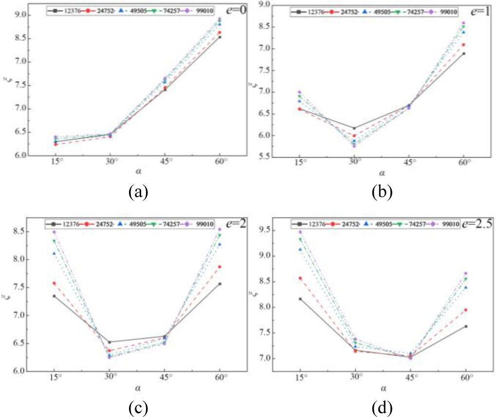
Fig. 5.
Fig. 6.
Fig. 7.
Fig. 8.
Fig. 9.
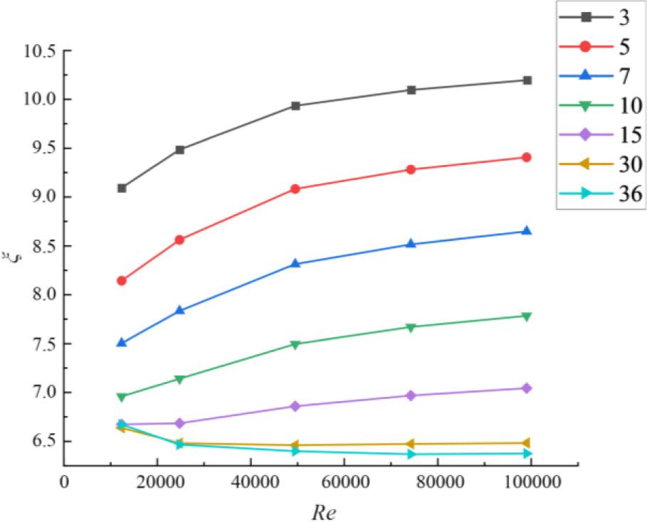
Fig. 10.
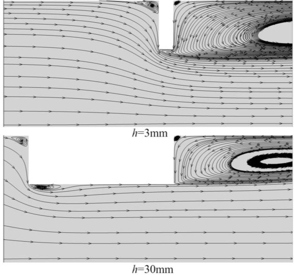
Fig. 11.
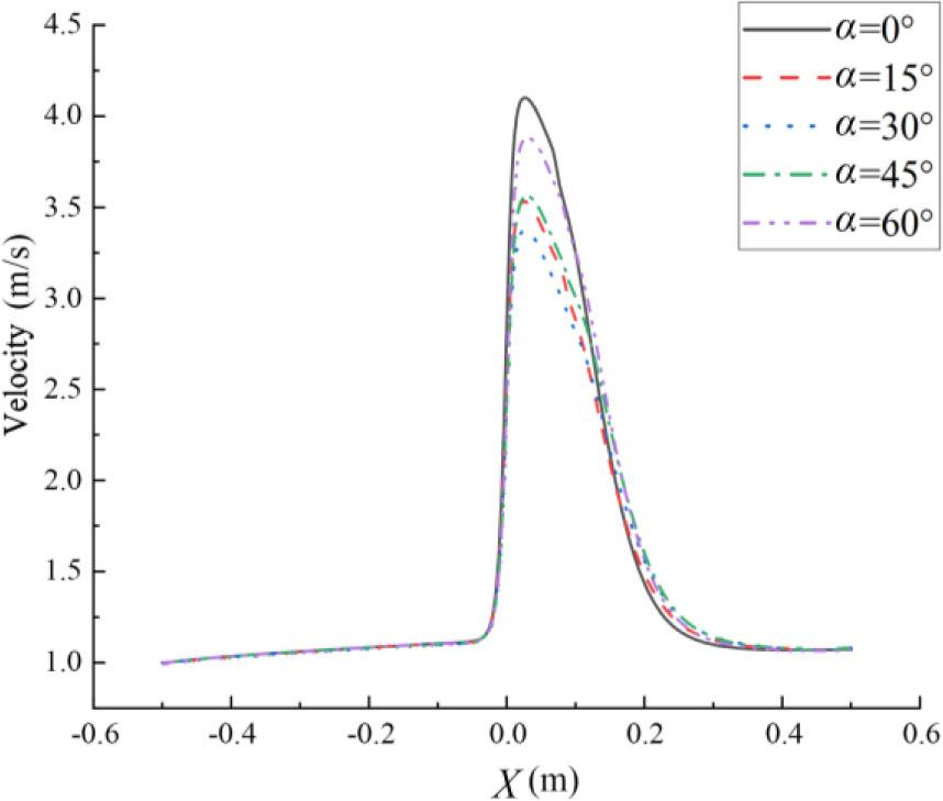
Fig. 12.
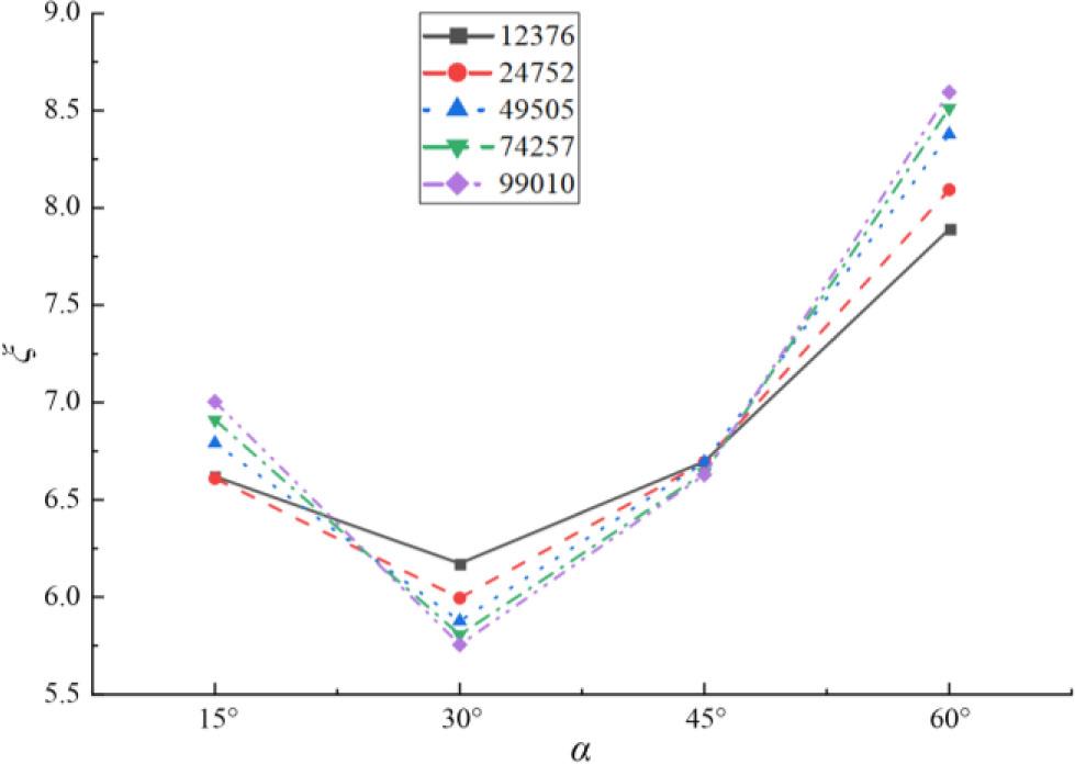
Fig. 13.
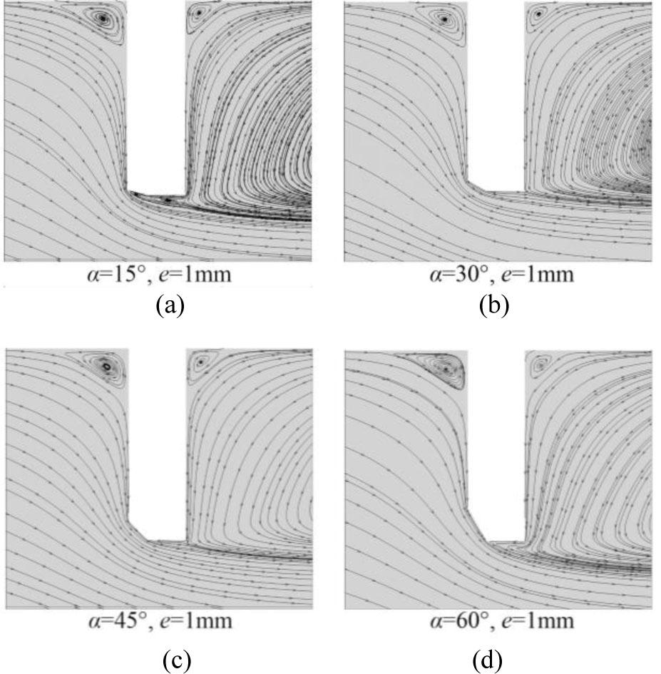
Fig. 14.
| Nomenclature and abbreviations | |
|---|---|
| Latin letters | |
| D | Pipe inner diameter [m] |
| d | Orifice (bore) diameter [m] |
| h | Orifice plate thickness [m] |
| e | Orifice bore thickness after chamfering [m] |
| U | Inlet mean velocity [m·s−1] |
| P | Static pressure [Pa] |
| ΔP | Differential pressure across the orifice plate [Pa] |
| Δπ | Permanent pressure loss [Pa] |
| Cd | Discharge coefficient |
| Greek letters | |
| α | Upstream chamfer (bevel) angle [°] |
| β | Diameter ratio, β = d/D |
| μ | Dynamic viscosity [Pa·s] |
| ν | Kinematic viscosity [m2·s−1] |
| ρ | Density [kg·m−3] |
| ξ | Pressure loss coefficient |
| Dimensionless groups | |
| Re | Reynolds number, Re = ρUD/μ |
| t | Relative plate thickness, t = h/d |
Chamfered orifice plate structure parameters_
| Diameter ratio β | Thicknesses h [mm] | Orifice bore thickness e [mm] | Chamfer angle α [°] |
|---|---|---|---|
| 0.6 | 3 | 1 | 15 |
| 0.6 | 3 | 1 | 30 |
| 0.6 | 3 | 1 | 45 |
| 0.6 | 3 | 1 | 60 |
| 0.6 | 3 | 2 | 15 |
| 0.6 | 3 | 2 | 30 |
| 0.6 | 3 | 2 | 45 |
| 0.6 | 3 | 2 | 60 |
| 0.6 | 3 | 3 | 15 |
| 0.6 | 3 | 3 | 30 |
| 0.6 | 3 | 3 | 45 |
| 0.6 | 3 | 3 | 60 |
Structural parameters of throttled orifice plates with different thicknesses_
| Throttle orifice d [mm] | Beta ratio β | Thickness h [mm] | Relative thickness t |
|---|---|---|---|
| 30 | 0.6 | 3 | 0.10 |
| 30 | 0.6 | 5 | 0.17 |
| 30 | 0.6 | 7 | 0.23 |
| 30 | 0.6 | 10 | 0.33 |
| 30 | 0.6 | 15 | 0.50 |
| 30 | 0.6 | 30 | 1.00 |
| 30 | 0.6 | 36 | 1.20 |
Orifice plate chamfering parameters_
| Thicknesses h [mm] | Orifice bore thickness e [mm] | Chamfer angle α [°] |
|---|---|---|
| 3 | - | 90 |
| 3 | 1 | 15 |
| 3 | 1 | 30 |
| 3 | 1 | 45 |
| 3 | 1 | 60 |