

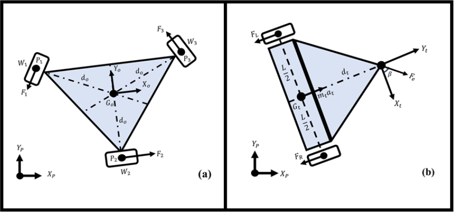
Figure 1.
2D illustration of (a) omniwheel mobile robot and (b) trailer
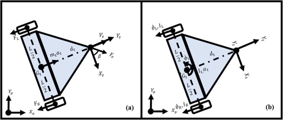
Figure 2.
Forces (a), torques (b) on trailer
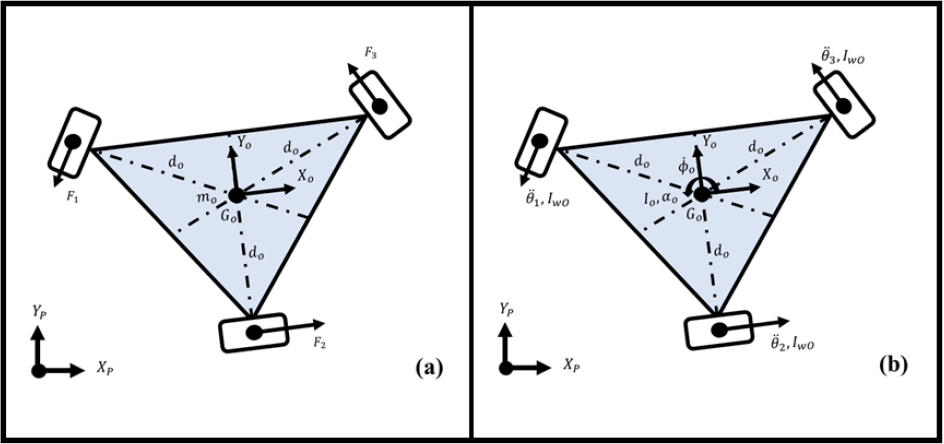
Figure 3.
Forces (a), torques (b) on omniwheel mobile robot
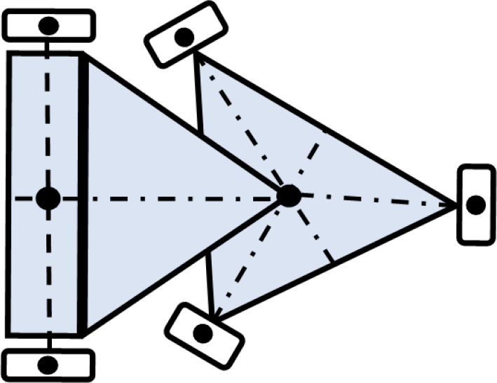
Figure 4.
Mobile robot integrated trailer representation
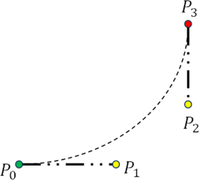
Figure 5.
Cubic Bézier curve
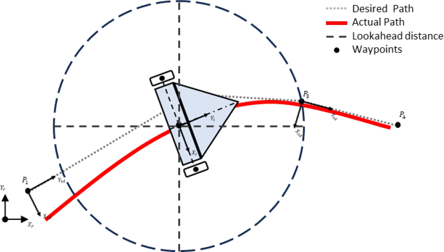
Figure 6.
Pure pursuit algorithm
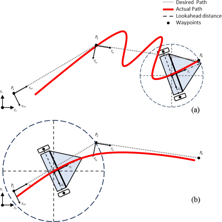
Figure 7.
Pure pursuit algorithm example for (a) low, (b) high lookahead distance
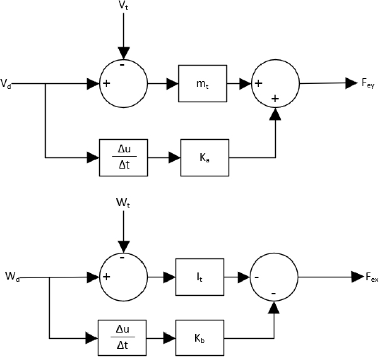
Figure 8.
Dynamic tracking control
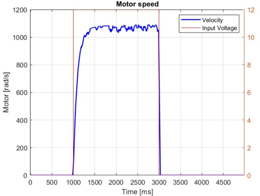
Figure 9.
Input voltage and output velocity against time
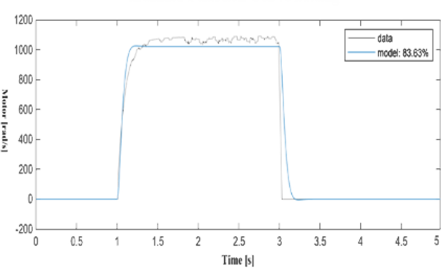
Figure 10.
Curve fitting of the transfer function
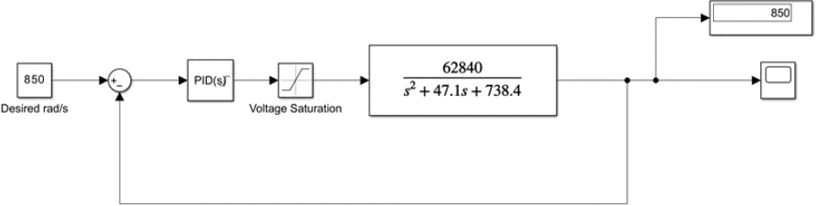
Figure 11.
Tested motor transfer function and PID parameters
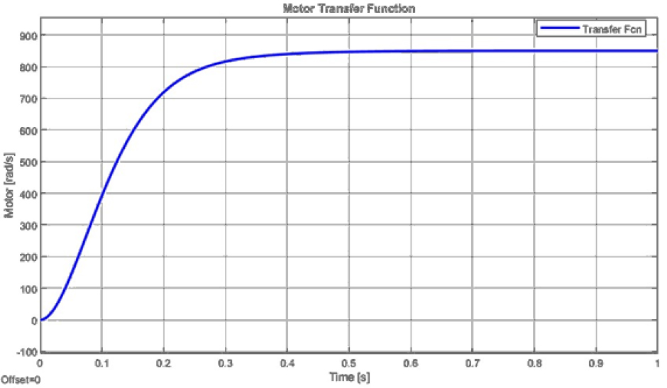
Figure 12.
PID controlled motor transfer function
Table 1.
Tuned PID Parameters
| P | I | D | N | |
|---|---|---|---|---|
| Motor 1 | 0.231 | 0.358 | 0.007 | 15796.2 |
| Motor 2 | 0.158 | 0.493 | 0.011 | 5750.9 |
| Motor 3 | 0.166 | 0.535 | 0.012 | 6962.8 |
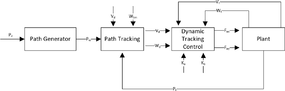
Figure 13.
Simulation block diagram of trailer control
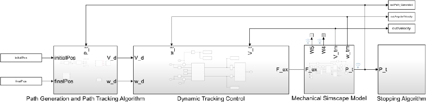
Figure 14.
Trailer control simulation in MATLAB Simulink
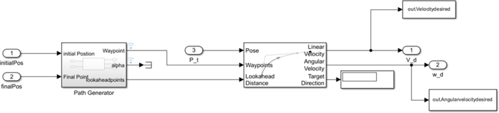
Figure 15.
Subsystem of path generation and path tracking algorithm
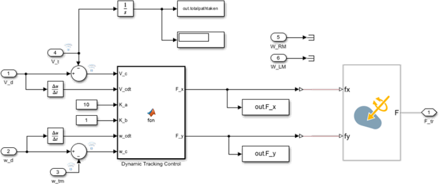
Figure 16.
Dynamic tracking control subsystem
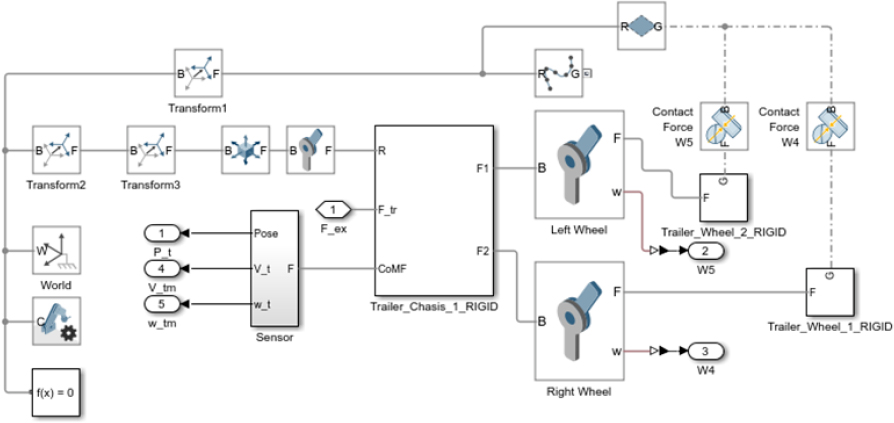
Figure 17.
Subsystem of the trailer mechanical Simscape model
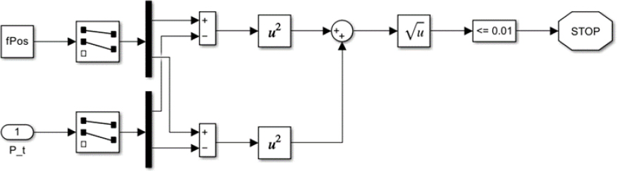
Figure 18.
Stopping algorithm of the trailer
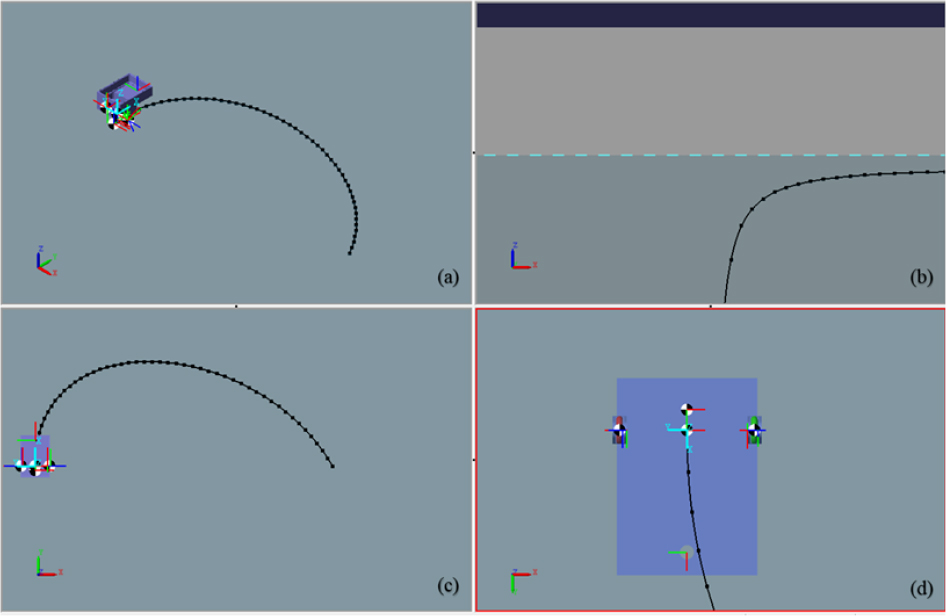
Figure 19.
Simulation start, the trailer is at the beginning of the path (a) isometric view, (b) front view, (c) top view, (d) bottom view
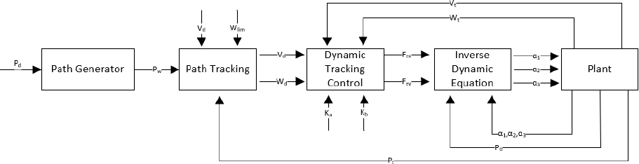
Figure 20.
Simulation Block Diagram of the tractor robot
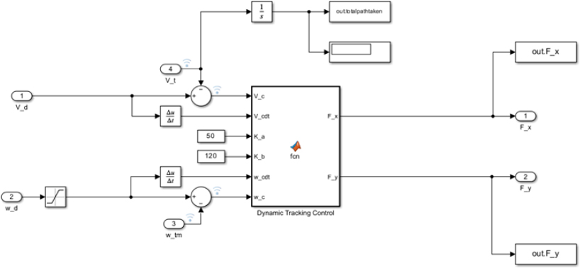
Figure 21.
Subsystem of dynamic tracking control of trailer towed by omniwheel mobile robot
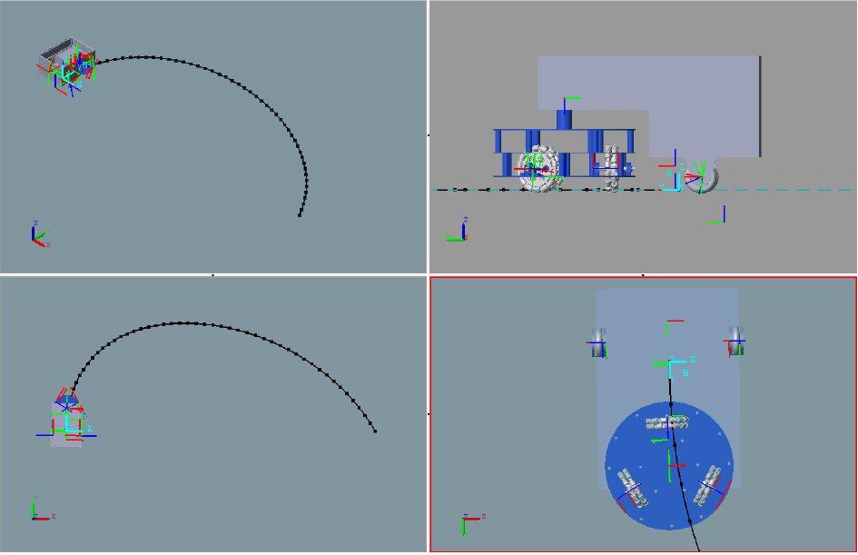
Figure 22.
Simulation start, the mobile robot and trailer are at the beginning of the path (a) isometric view, (b) left view, (c) top view, (d) bottom view
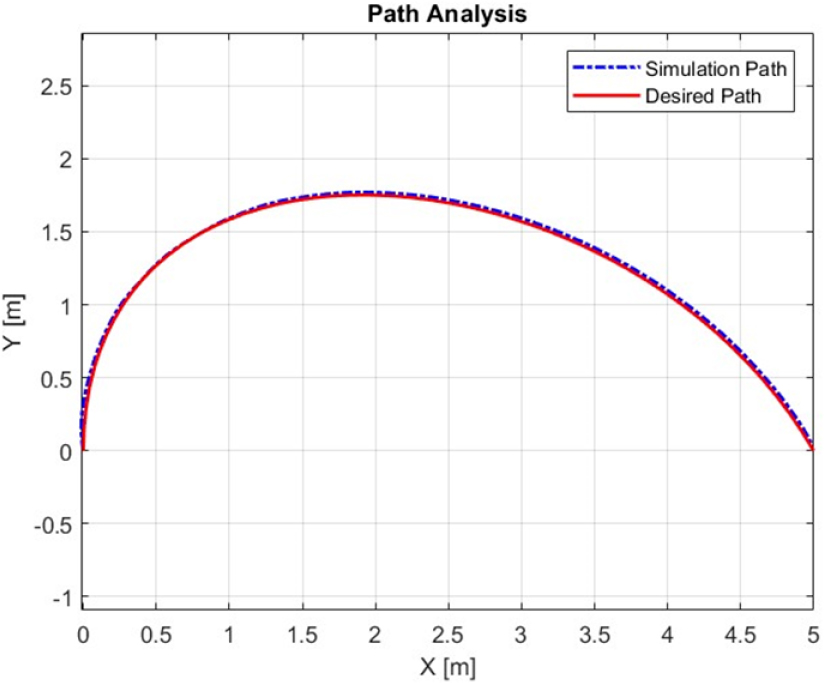
Figure 23.
Bézier Curve path analysis with tuned parameters
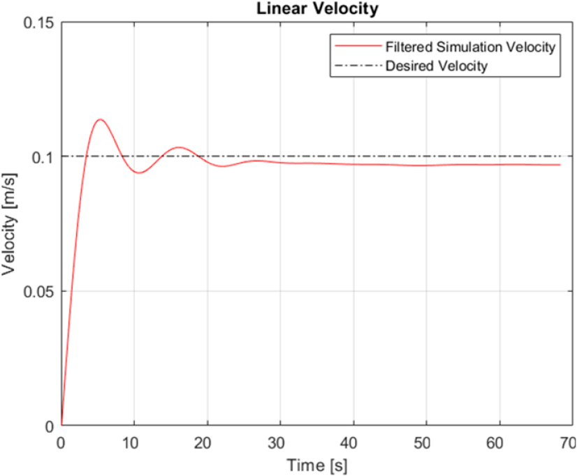
Figure 24.
Linear velocity of the towed trailer
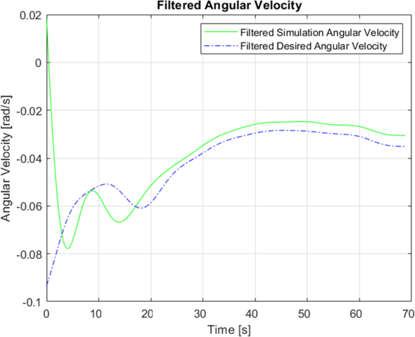
Figure 25.
Angular velocity of towed trailer
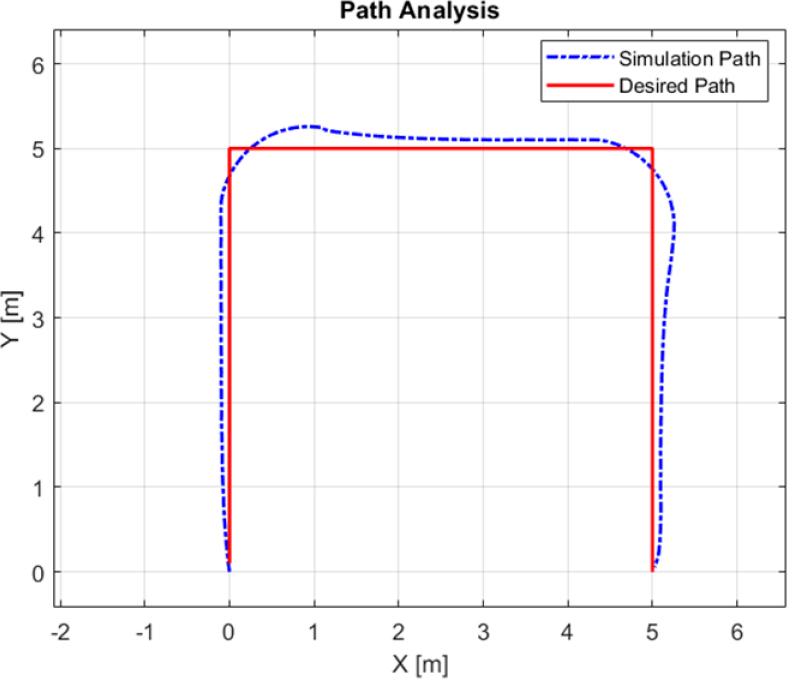
Figure 26.
Square path analysis (D=0.75 m)
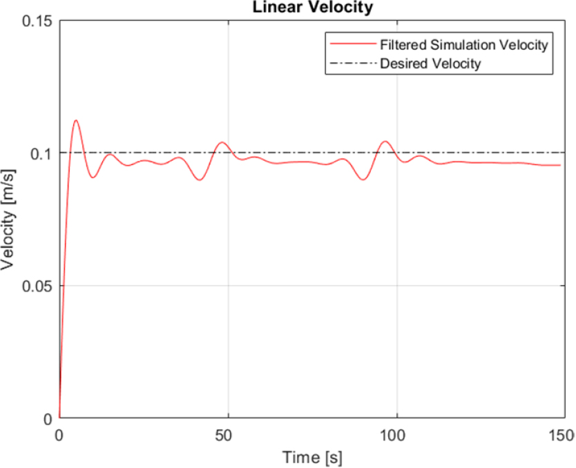
Figure 27.
Linear velocity of towed trailer on square path
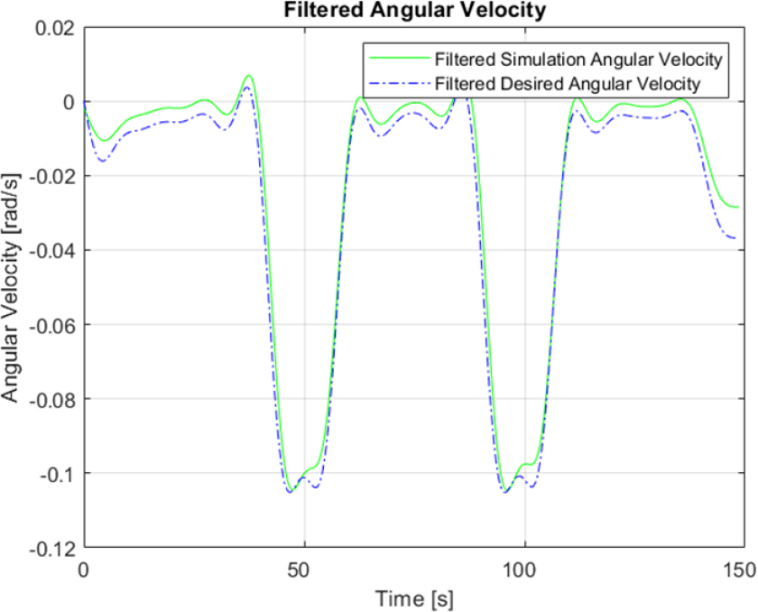
Figure 28.
Angular velocity of towed trailer on square path
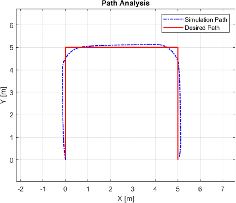
Figure 29.
Square path analysis (D=1.25 m)
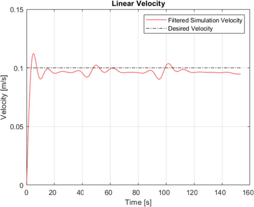
Figure 30.
Linear velocity of towed trailer on square path
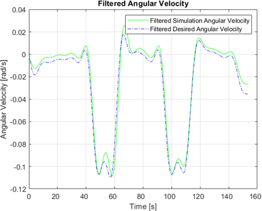
Figure 31.
Angular velocity of towed trailer on square path
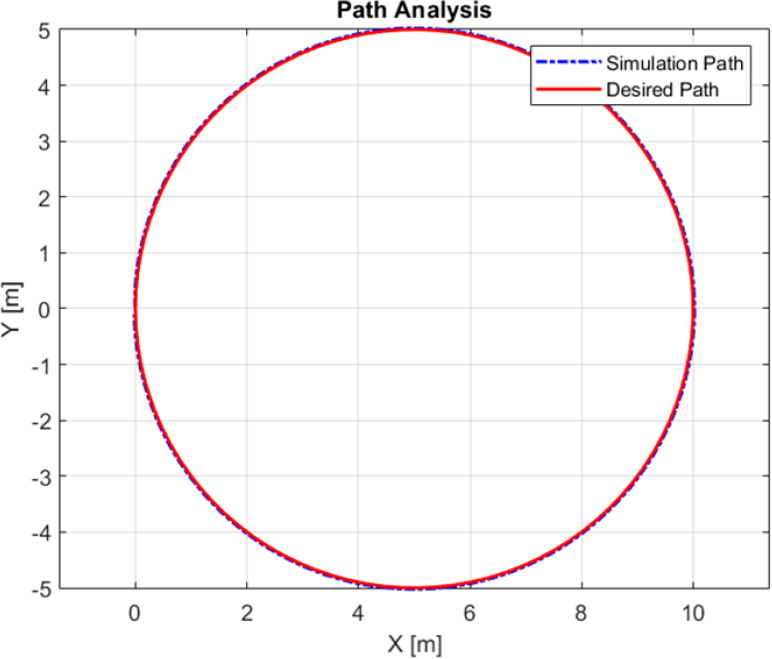
Figure 32.
Circular path analysis
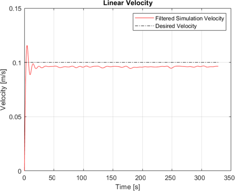
Figure 33.
Linear velocity of towed trailer on circular path
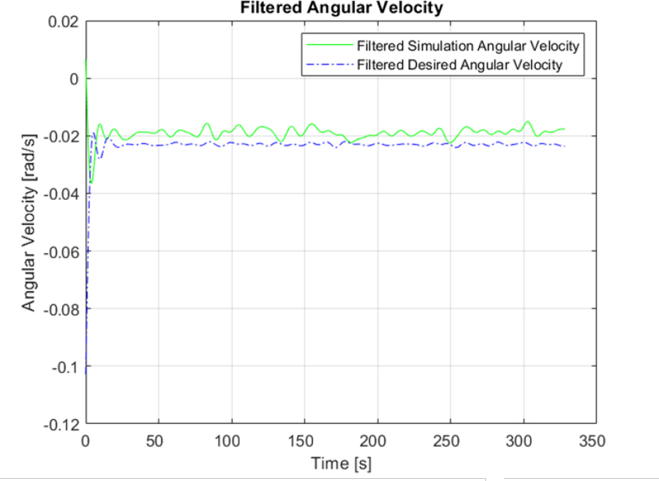
Figure 34.
Angular velocity of towed trailer on circular path
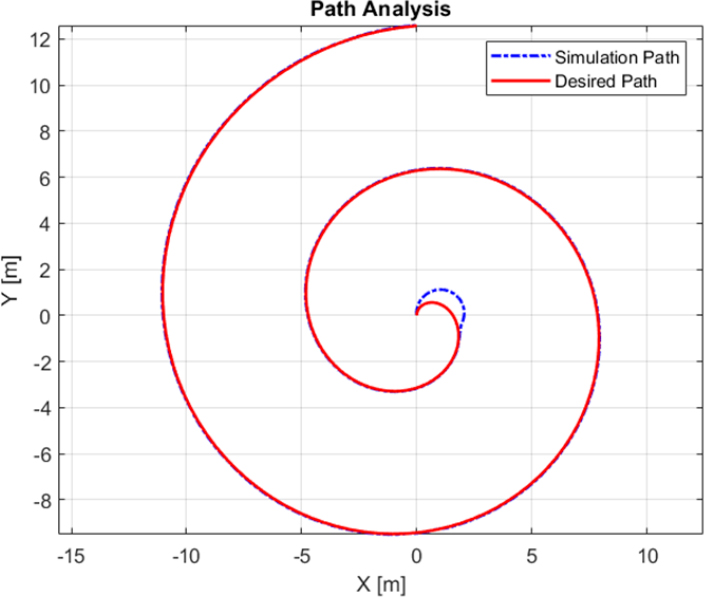
Figure 35.
Archimedean spiral path analysis
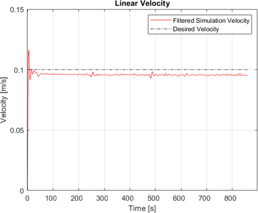
Figure 36.
Linear velocity of towed trailer on Archimedean spiral path
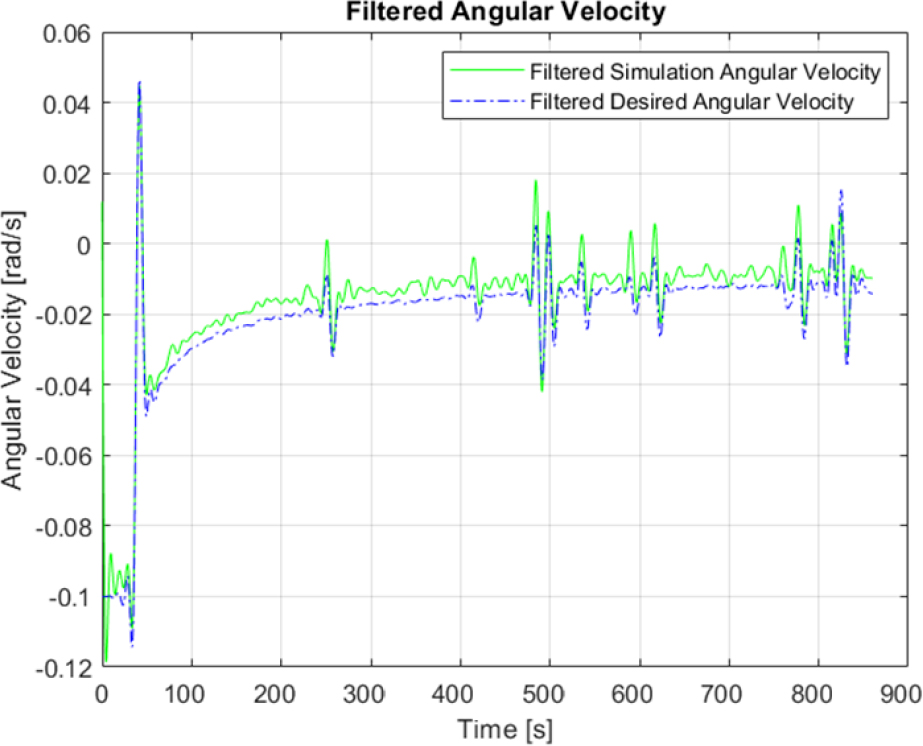
Figure 37.
Simulated vs desired angular velocity of towed trailer on Archimedean spiral path
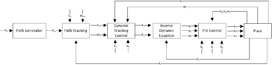
Figure 38.
Simulation block diagram including PID control
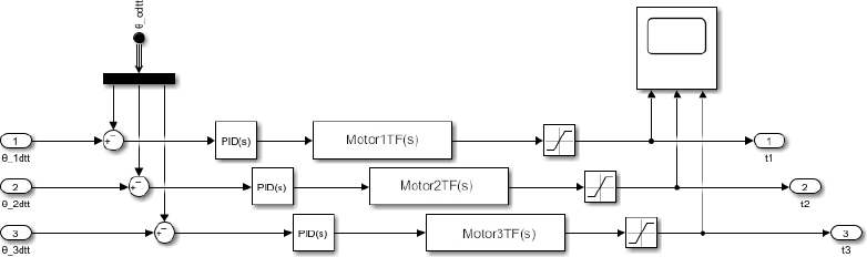
Figure 39.
Simulating the selected motors
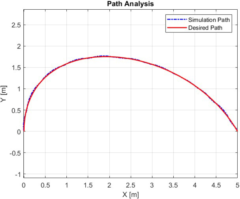
Figure 40.
Bézier curve path analysis with implementation of PID controlled dc motors
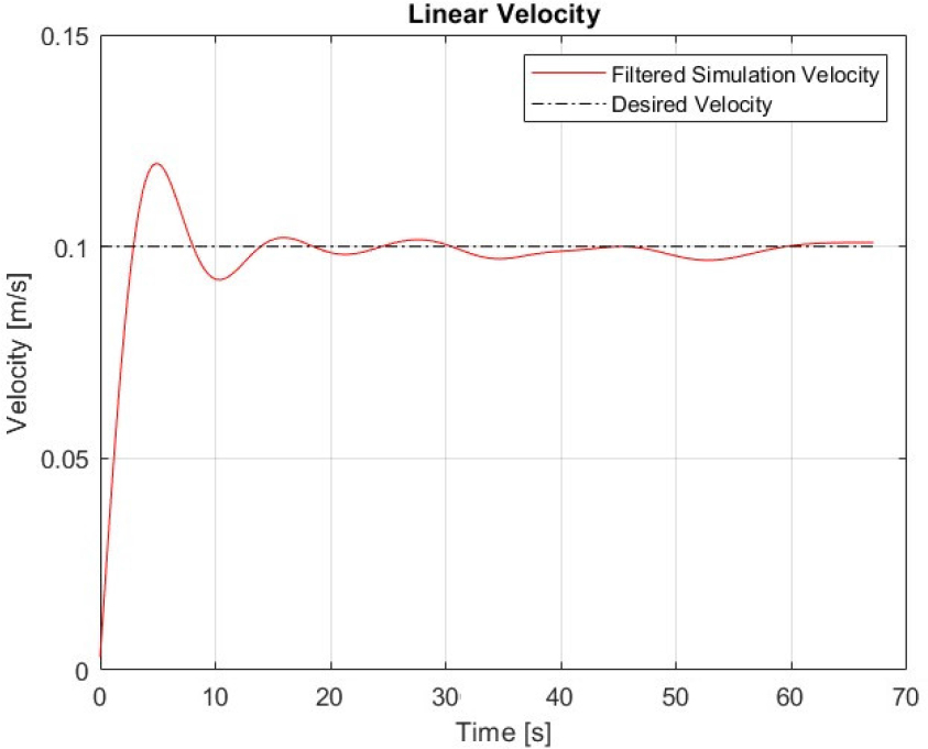
Figure 41.
Linear velocity of towed trailer on Bézier curve path with implementation of PID controlled dc motors
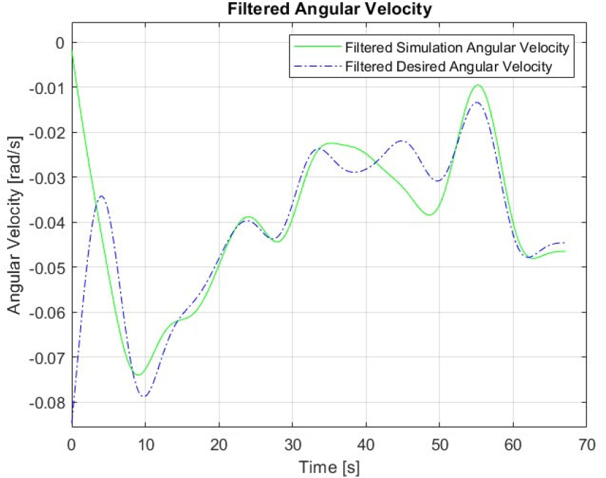
Figure 42.
Angular velocity of towed trailer on Bézier curve path with implementation of PID controlled dc motors
Table 2.
Performance Comparison of Non-Tuned, Tuned, and Motor Integrated PID Tuned Controllers
| Metric | Non-Tuned | Tuned | Motor Integrated PID Tuned |
|---|---|---|---|
| Steady State Linear Velocity Error (Vess,%) | 13.29 | 6.26 | 4.32 |
| Linear Velocity Overshoot (%) | 8.68 | 17.48 | 17.17 |
| Steady State Time (Tss, s) | N/A | N/A | 61.9 |
| Maximum Angular Velocity Error | 0.104 | 0.092 | 0.117 |
| Average Angular Velocity Error | 0.010 | 0.006 | 0.008 |
| Execution Time (s) | 74.7720 | 68.7573 | 67.2488 |
| Tracking Error (Max, m) | 0.0777 | 0.0755 | 0.0756 |
| Tracking Error (RMS, m) | 0.0425 | 0.0408 | 0.0404 |
| Tracked Path Length (m) | 6.620 | 6.620 | 6.630 |
| Planned Path Length (m) | 6.627 | 6.627 | 6.627 |