

Figure 1.
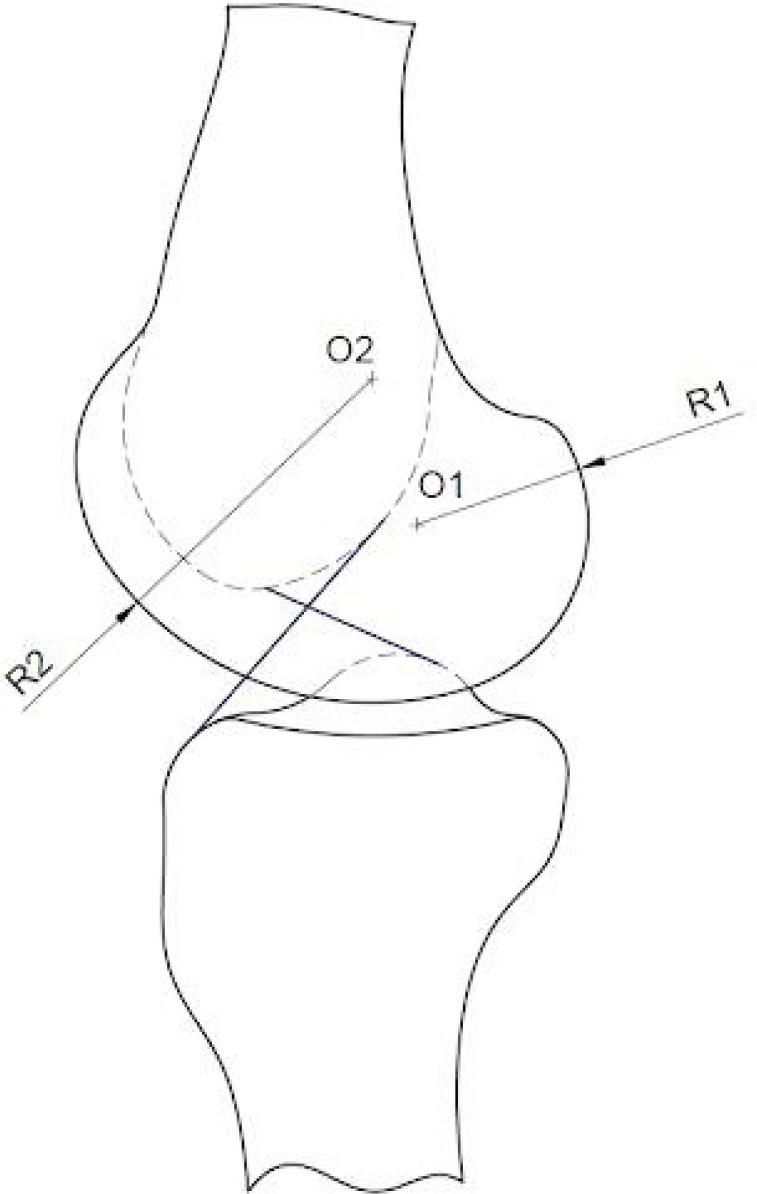
Figure 2.
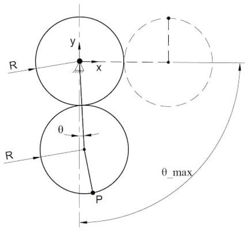
Figure 3.
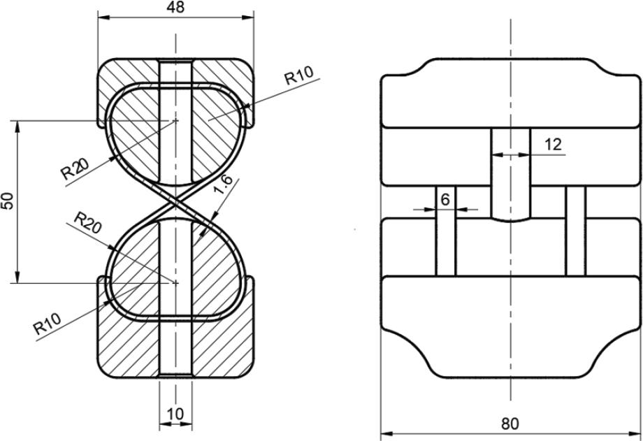
Figure 4.
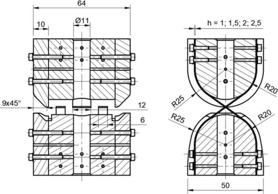
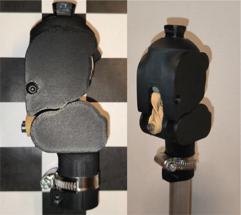
Figure 5.
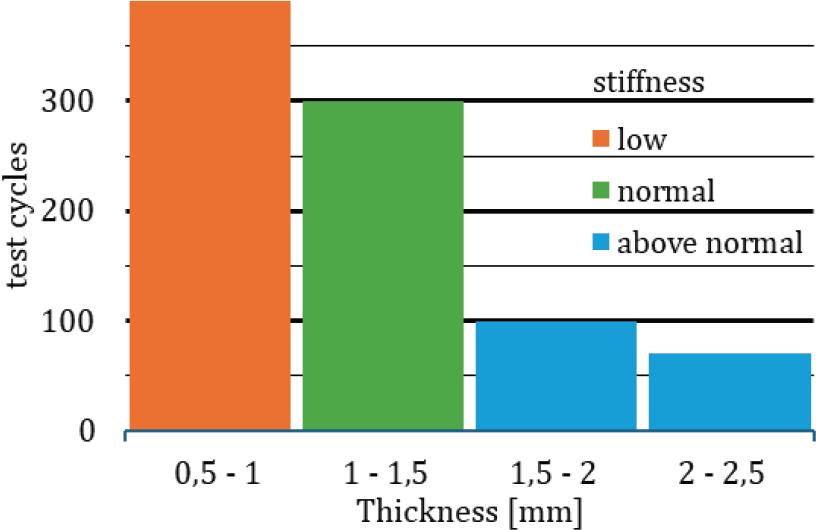
Figure 6.
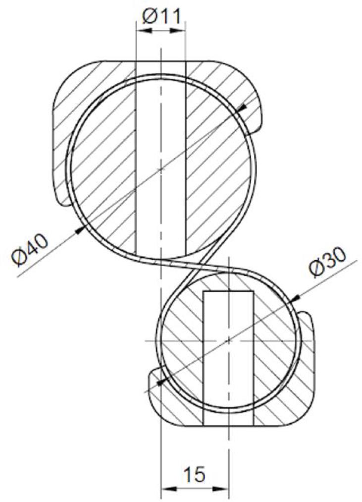
Figure 7.
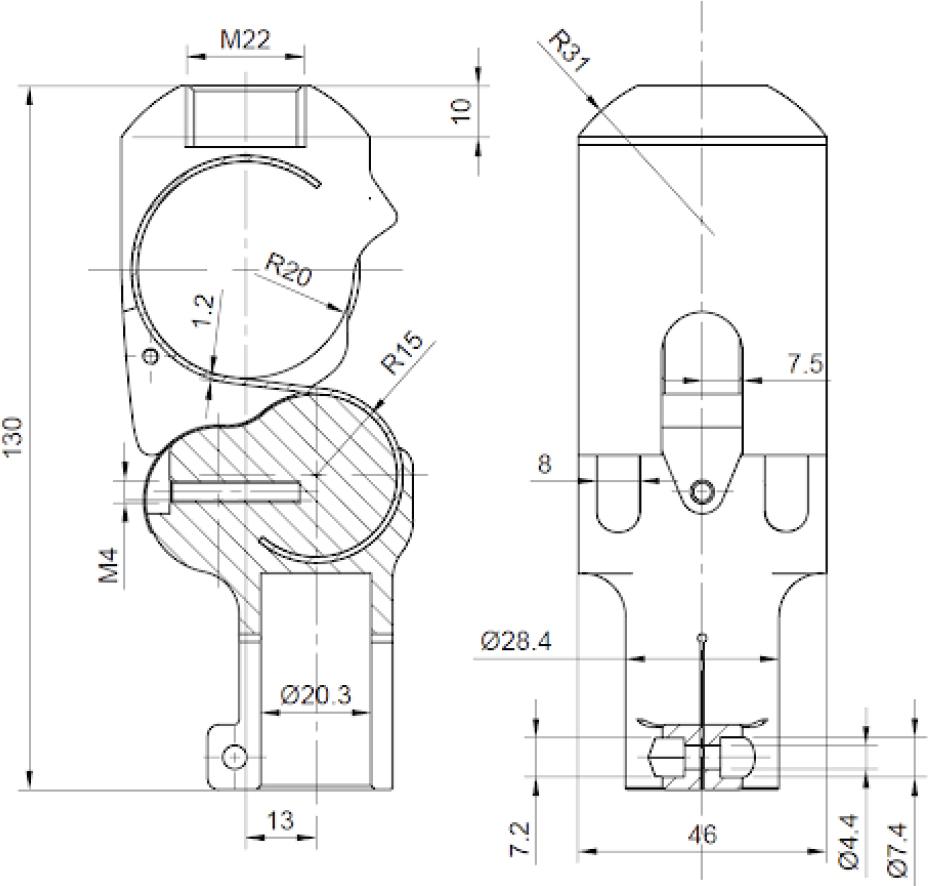
Figure 8.
Summary of the design progress of the compliant joint
| Design version | Rotation extent | Test type | Test results |
|---|---|---|---|
| Primary design | −180 to 180 deg | Manual full extent deformation and release | Joint returns to its primary position, no visible signs of shape alteration, visible signs of structural breaking after repeated tests |
| Primary design second iteration (band thickness test) | −180 to 180 deg | Cyclic manual full extent deformation | Thicker bands (1.5 mm to 2.5 mm) show better stiffness but break quickly (after 70–100 cycles), thin bands (0.5 mm to 1 mm) don’t break (>300 cycles) but are unstable. Optimal thickness is between 1 mm and 1.5 mm(breaking occurs at approx. 300 cycles) |
| Second design (asymmetric) | −101 to 144 deg | Cyclic manual full extent deformation | No signs of breaking after > 300 cycles, joint returns to primary position after repeated cyclic tests |
| Final design | 0 to 142 deg | Cyclic manual full extent deformation, static load test (74 kg in primary position) | No signs of breaking after >300 cycles, no signs of bands breaking during static test, no instability during static test. Further structural testing is needed |
| Final design with spring and damper mechanism | 0 to 142 deg | Cyclic manual full extent deformation and release | No signs of band deformation after >300 cycles, spring and damper mechanism aids the return of the joint to the primary position. Damping effect needs to be tested, spring stiffness needs to be tested and adjusted for different weights of artificial foot prostheses |