

Compliant mechanisms represent flexible devices with variable stiffness that gain their mobility through deformation [1, 2]. Compliant mechanisms are mechanical systems that achieve motion through the elastic deformation of flexible components, rather than through traditional rigid-body joints. This fundamental difference enables the creation of lightweight, monolithic structures with reduced part count, which in turn minimizes friction, wear, and the need for lubrication. These advantages make compliant designs particularly appealing in high-precision and biomedical applications, where simplicity, reliability, and compactness are critical. In contrast to conventional rigid joints— typically composed of multiple hard materials, such as steel or titanium, interacting through friction-prone interfaces—compliant joints operate through controlled material deformation. While this results in quieter and lower-maintenance devices, it introduces challenges such as limited fatigue life and susceptibility to overextension or material failure. Careful material selection and structural optimization are therefore essential for ensuring that compliant mechanisms meet the mechanical performance standards required in demanding applications, such as precision mechanics, biomedical engineering, and robotics [2].
A standard rotational rigid joint typically consists of three primary elements: Two bodies that are connected by a shaft. Each of these elements is fabricated from rigid and durable materials such as steel, aluminum, titanium, or bronze, chosen for their high strength and durability. The interaction between these components generates friction, which can lead to heat buildup, wear, and eventual failure if not properly managed. To mitigate friction and extend the lifespan of these joints, lubrication such as grease is applied regularly. Despite these measures, the nature of rigid joints means that they are still susceptible to mechanical wear and efficiency losses over time. The need for regular maintenance and the potential for mechanical failure are significant drawbacks in applications where reliability and longevity are crucial.
In contrast, a compliant joint is composed of a single element made from a specific flexible material. This material is engineered to deform elastically, accommodating motion without the need for multiple interacting parts. The ability of the compliant element to bend and flex under load is what provides the joint’s mobility. However, this reliance on material deformation also introduces limitations. The range of motion is constrained by the material’s properties, and excessive deformation can lead to fatigue and failure. Consequently, while compliant joints can reduce complexity and eliminate friction, they are generally less durable and have a shorter fatigue life compared to their rigid counterparts. These limitations must be carefully considered and addressed in the design phase to ensure that compliant mechanisms meet the required performance standards in their intended applications.
When considering the replacement of rigid joints with compliant mechanisms, it is crucial to thoroughly understand and mitigate the weaknesses inherent in compliant designs. Rigid body mechanisms generally surpass compliant mechanisms in terms of durability and fatigue life [2].
An under-designed compliant structure may exhibit fragility and a reduced operational lifespan, which can be problematic in demanding applications. Therefore, careful material selection, design optimization, and thorough testing are essential to ensure that compliant mechanisms can reliably replace rigid joints in practical applications. This understanding is vital when integrating compliant joints into structures traditionally dominated by rigid body equivalents, particularly in scenarios where reliability and longevity are paramount.
Artificial prosthetic limb design is a continuously evolving branch of biomechanical engineering, focused on developing prosthetics that closely replicate the mechanical characteristics of natural limbs. The primary goals of this field are to provide comfort, functionality, and independence to users through the development of advanced prosthetic devices. Compliant mechanisms, inspired by the natural compliance found in biological joints, offer promising potential in this regard [3–5]. The incorporation of compliant mechanisms into prosthetic limb design could lead to devices that are not only lighter but also capable of more natural and efficient movement [6, 7]. By mimicking the behavior of biological joints, compliant mechanisms could significantly enhance the performance and user experience of prosthetic limbs, marking a substantial advancement in the field. Compared to typical prostheses, there is no harmful movement of areas of the body that are not naturally involved in performing a given movement or task [8]. Additional advantages over traditional mechanisms include the elimination of the need for lubrication, no noise or oscillations, and wear caused by joint clearances [9].
Advances in additive manufacturing technologies have enabled the precise production of various types of prosthetics [10, 11] and exoskeletons [12]. In parallel, progress in control systems—such as brain-computer interfaces (BCIs)—shows promise for enhancing user interaction with prosthetic devices [13]. Together, these developments highlight the growing convergence of mechanical innovation and neurotechnology in modern prosthetic design.
This study investigates the integration of a compliant rolling-contact mechanism into the design of an artificial knee joint, drawing on the principles of CORE and D-CORE joint architectures. A series of prototypes were developed using 3D printing, with successive iterations addressing challenges related to flexure band durability, range of motion, and overextension control. The goal was to create a compliant knee joint capable of replicating the hybrid kinematics of both single-axis and polycentric designs, while laying the groundwork for a future prosthesis with reduced complexity and enhanced biomechanical performance.
The human knee joint is built out of four bones, five ligaments and nine muscles. The motion of the human knee joint is a complex operation to be described kinematically [14]. However, when designing a prosthetic knee joint, the kinematics of the biological knee can be simplified. Similar approaches were utilized in the kinematic modelling of other biological structures, where simplified mechanisms successfully replicate complex movements while preserving structural fidelity [15].
At a basic level, the kinematic motion of the human knee is described with the femur, tibia bones and cruciate, collateral ligaments. The ligaments create restraints for the tibia and femur, defining their basic motion and limits. Collateral ligaments serve to restrain the tibia from moving in a sideways motion in reference to the femur. The cruciate ligaments limit the forward and backward movements of the tibia in reference to the femur. Additionally, the positions of the cruciate ligaments allow for the tibia and femur to constantly maintain contact during the movement of the knee. The tibia rotates around the tip of the femur, which can be simplified to a 2D plane as a geometry consisting of two radii: R1 and R2. The scheme is presented in Figure 1.
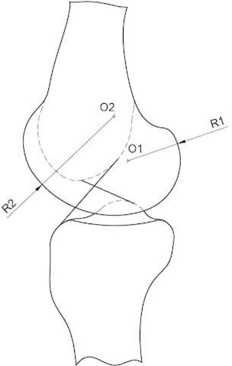
2D Scheme of knee joint
Artificial prosthetic knee joints are built to emulate the previously mentioned kinematic model of a biological human knee joint. However, some artificial knee types, like single-axis knee joints, do not entirely emulate this model. Because single-axis knee joints have only one axis of rotation, they refer to an extremely simplified knee model where the trajectory follows only one radius. Most widely designed polycentric knees have four axes of rotation.
These four axes are connected in pairs with two beams of various lengths. This construction presents a rigid body analogue to a cruciate ligament system. Because the lengths of the beams are different, the rotational movement of the artificial polycentric knee can be portrayed in two radii.
The mechanical complexity of artificial knee joints can be appropriated to four K-level functionality groups [16, 17], and [18]. K-1 and K-2 level devices are meant to serve patients with the basic need of movement indoors and minimum activity outdoors on flat surfaces. K-3 and K-4 level devices are designed for patients with most high outdoor activity including training various sports. As noted in both marked trends and literature, K-1 and K-2 level artificial limb constructions most usually consist of a simple spring and damper mechanism where the movement is complemented with a stainless steel spring and the extension of the joint is dampened with a viscoelastic material. K-3 and K-4 level artificial limbs are usually designed with a hydraulic or pneumatic spring and damper system. These systems allow damping throughout the whole cycle of motion of an artificial knee. This then defines a smoother operating knee, allowing for longer periods of intense walking or exercise.
The concept of design of the compliant prosthetic knee joint derives from the CORE and D-CORE compliant revolute joint design [19, 20]. The CORE compliant joint represents a potential substitute to a rigid 1 DOF pin-in-hole type hinge mechanism. A pin-in-hole hinge generates friction and wear. The kinematic concept of the CORE is of two cylindrical bodies creating a revolute motion by rolling, which generates less wear and friction. The two cylindrical cams are connected with flexure bands that constrain the freedom of movement of the rigid cylindrical bodies, defining the movement in a specified way.
The movement between the cylindrical bodies of the CORE joint is illustrated in Figure 2. As the lower cylinder rotates at an angle of θ point P of the lower cylinder rotates at an angle of 2θ. To maintain contact between the cylinders and prevent sliding and friction, additional flexure bands are used. The flexure bands connect the two bodies and restrict their movement. Moreover, the flexure bands define the rolling contact motion because of the joint’s construction.
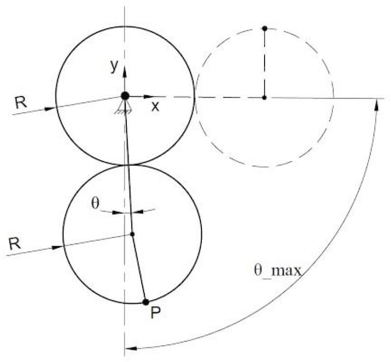
CORE joint – movement between the cylindrical bodies
The primary design concept consisted of a modified compliant CORE design. By default, the thickness of the flexure bands of the CORE is small. The alteration involved increasing the thickness of the flexure bands which resulted in higher stiffness. The initial thickness of the bands was set to 2 mm which in assumption created a zero position for the joint which the mechanism returned to after any kind of rotation. Given the higher stiffness of the bands in comparison to the D-CORE, a certain distance had to be set between the upper and lower cylinders so that the joint would not become rigid and lack the needed rotational movement. The contact points for both cylinders haven’t been added yet since the primary design was meant to test the rotational movement capabilities of the joint. The model is presented in Figure 3.
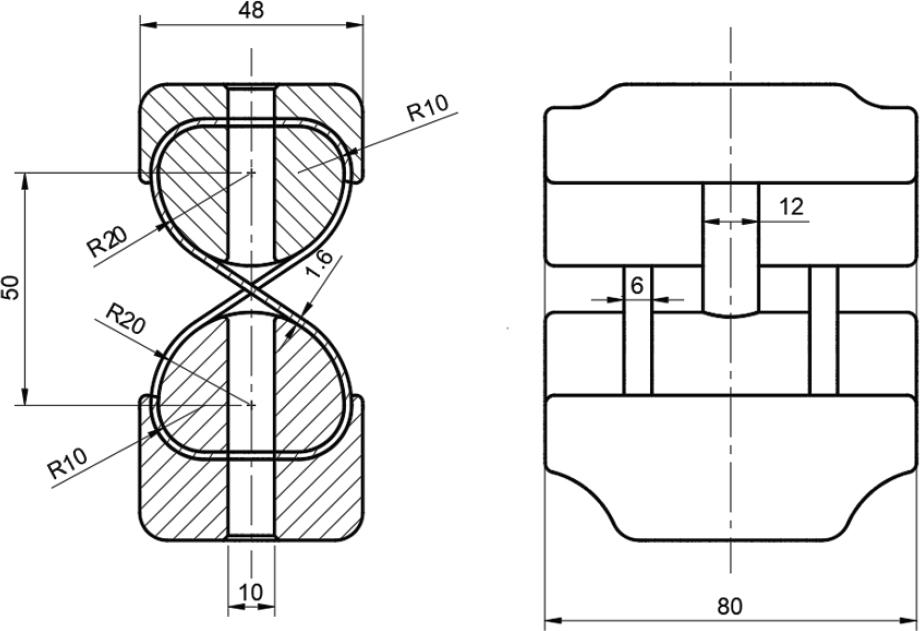
Initial concept – technical drawing
The model was designed for multi-material 3D printing to prevent the flexure bands from sticking to the walls of the cylindrical bodies during fabrication. For the purpose of not using additional elements the connection between the flexure bands and the cylindrical bodies was established in the mechanical design by merging the double material walls together which resulted in the bands staying firm in the cylindrical bodies. The material of choice for the cylindrical cams was PET-G filament due to its durability and low cost. For the flexure bands PA+GF (Nylon with infused glass fiber particles) filament was used as it offers favorable flexibility and resistance to deformation in relation to stiffness. Specifically, PA12+GF15—a composite containing 15% glass fiber by weight in a polyamide matrix—was employed. Due to the nature of this material, the print speed was reduced to improve interlayer adhesion and minimize thermal warping. All parts were printed using a standard 0.4 mm nozzle with a 0.2 mm layer height. Compliant components were printed solid (100% infill), with all toolpaths aligned along the length of the part.
After the primary design concept was manufactured, the kinematic mechanical capabilities of the model were tested. The joint was deformed to its full extent and then released to confirm that the bands return to their initial position. The model showed promising results as the reaction to the deformation of the nylon flexure bands confirmed the assumptions. The shape of the bands did not alter and effortlessly returned to their original form.
However, after some cycles of testing, the bands showed signs of possible breaking at the points where they were fixed to the cylindrical bodies. The extent of the deformation depending on the thickness of the flexure bands had to be analyzed.
A new model design was developed for flexure band thickness analysis. The design made it possible to remove and attach the flexure bands to the cylindrical bodies. The goal was to establish an optimal flexure band thickness which was characterized by suitable stiffness and long lifespan. The model can be seen in Figure 4.
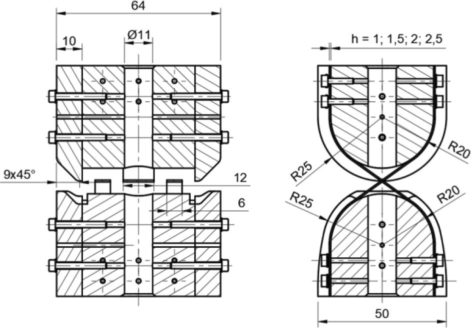
Model after first stage of modification – technical drawing
The range of thickness to be tested for the nylon bands was between 0.5 mm and 2.5 mm. In addition to thickness, the impact of the width of the flexure bands was tested. The width of the tested bands ranged from 8 mm to 15 mm.
Similar tests were conducted as to the primary design model. Results from the tests (Fig. 5) indicated that thicknesses ranging from 1 mm to 1.5 mm exhibited the most promising characteristics the joint showed no signs of failure after approximately 300 cycles and the stiffness characteristics were sufficiently returning the joint to the zero position.
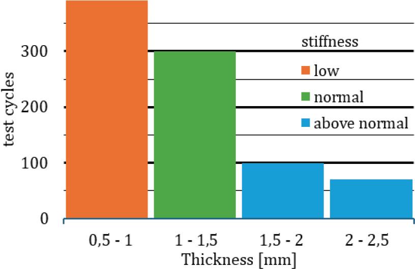
Tests results
The number of cycles were a satisfactory result, considering that thickness of 1.5 mm to 2.5 mm showed signs of breaking after approximately 70–100 cycles. Elements with thickness of 0.5 mm to 1 mm showed good resilience to breaking, however, low stiffness led to instability of the zero position of the compliant joint. The width of the elements did not display influence in breaking resistance, but elements with widths of over 10 mm demonstrated good resistance to twisting movements of the joint. To verify the fatigue strength of compliant components, tests conducted on a testing machine under controlled conditions are planned as part of future research.
The thicker flexure bands of the modified CORE model displayed signs of overbending when rotating the joint to an extent of minimum 130 degrees. Regarding a standard knee prosthetic device, the maximum angle of rotation is defined as 142 degrees. Overextension of flexure bands could lead to a low life cycle of such a compliant joint, thus further adjustments were made.
To reduce the extent of deformation of the flexure bands, the position of the cylindrical bodies was changed from symmetric to asymmetric—the lower cylinder and its vertical axis positions were shifted up to 15 mm from the upper cylinder’s vertical axis. The shift value of 15 mm was determined based on experimental testing. This asymmetrical arrangement created two movement characteristics for the flexure bands, short and long. The long movement deforms the flexure bands more than the previous model and creates a larger angle of overextension. In contrast, the short movement characteristic deforms the flexure bands less, preventing overextension. Because the movement of a prosthetic knee joint is one sided, the side that characterizes in a larger deformation of the bands was considered as the front of the joint. A modification was made to the model to restrict its forward movement.
The asymmetric configuration of the compliant joint minimized the maximum extent of its rotation which was below 142 degrees. An additional alteration was done to the model to define its rotation limit to approximately 142 degrees. This was achieved by downscaling the diameter of the lower cylinder to ¾ of the upper cylinder’s diameter. The design is displayed in Figure 6.
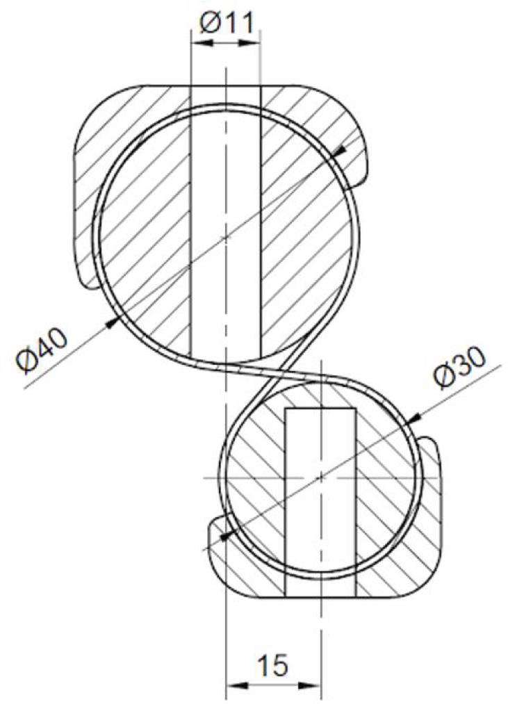
Design of second stage of modification – technical drawing
The last modification of the model defined the final construction of the compliant rotational joint of the prosthetic knee device prototype. Cyclic tests were conducted to evaluate the kinematics of the compliant joint and to confirm the optimization applied to the model.
In comparison to the symmetrical D-CORE joint in the view of an artificial knee joint design, the asymmetrical joint shows a more desirable structural characteristic. The flexure of the joint in the extent of 142 degrees does not show signs of overextensions on the flexure bands.
The final version of the kinematically tested compliant joint was adapted to a prosthetic knee joint design concept. An element known as the pyramid adapter was added to the upper cylinder body. This allows the prosthetic joint to be properly aligned and attached to the leg socket. For the lower body, a tube adapter extension was added. A 25 mm diameter tube could be attached to connect the prosthetic knee device with a prosthetic foot, completing the whole assembly. A pyramid adapter can also be designed for the lower body since it is a universal linking element used in lower limb prosthetic construction. The design of the final version is presented in Figure 7.
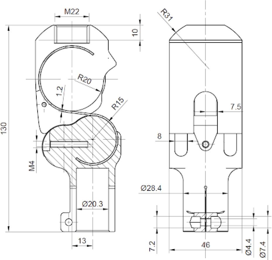
Final version – technical drawing
A simple spring-damper mechanism was designed for the 3D-printed compliant prosthetic joint. This could possibly classify the knee joint as K-1, K-2 level. However, to fully classify the prosthetic knee joint further studies and optimization have to be done to the spring-damper mechanism since this study does not cover it. The spring-damper system consists of a viscoelastic band connecting the upper and lower body cylinders and dampers, 3D printed out of TPU filament, which mitigate the impact when the joints return to the zero position. The printed prototype of the knee joint is presented in Figure 8. The summary of the design process and performed tests are presented in Table 1.
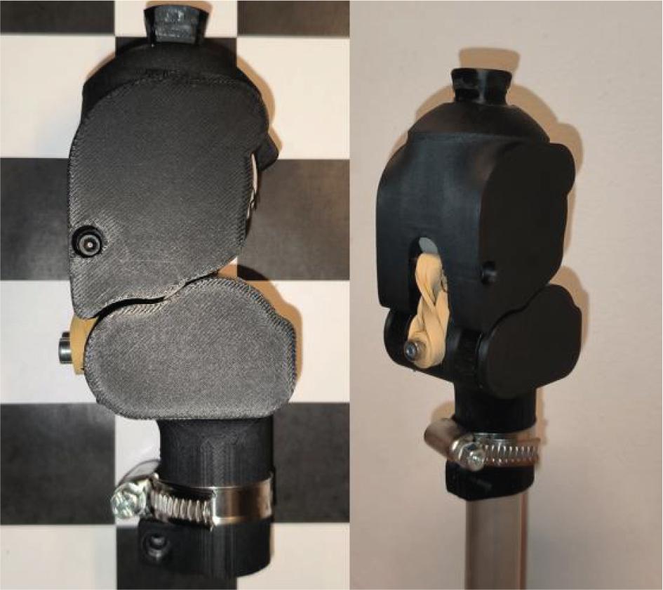
Printed knee joint protype – photo
Summary of the design progress of the compliant joint
| Design version | Rotation extent | Test type | Test results |
|---|---|---|---|
| Primary design | −180 to 180 deg | Manual full extent deformation and release | Joint returns to its primary position, no visible signs of shape alteration, visible signs of structural breaking after repeated tests |
| Primary design second iteration (band thickness test) | −180 to 180 deg | Cyclic manual full extent deformation | Thicker bands (1.5 mm to 2.5 mm) show better stiffness but break quickly (after 70–100 cycles), thin bands (0.5 mm to 1 mm) don’t break (>300 cycles) but are unstable. Optimal thickness is between 1 mm and 1.5 mm(breaking occurs at approx. 300 cycles) |
| Second design (asymmetric) | −101 to 144 deg | Cyclic manual full extent deformation | No signs of breaking after > 300 cycles, joint returns to primary position after repeated cyclic tests |
| Final design | 0 to 142 deg | Cyclic manual full extent deformation, static load test (74 kg in primary position) | No signs of breaking after >300 cycles, no signs of bands breaking during static test, no instability during static test. Further structural testing is needed |
| Final design with spring and damper mechanism | 0 to 142 deg | Cyclic manual full extent deformation and release | No signs of band deformation after >300 cycles, spring and damper mechanism aids the return of the joint to the primary position. Damping effect needs to be tested, spring stiffness needs to be tested and adjusted for different weights of artificial foot prostheses |
The integration of a rotational compliant mechanism with a standard prosthetic knee joint construction resulted in a kinematic prototype of a polycentric compliant prosthetic knee joint. The compliant joint, constructed from cylinders with a constant radius, does not fully replicate the kinematics of a four-axis polycentric knee joint. Instead, the kinematics of the compliant joint can be described as a hybrid between a single-axis and a four-axis polycentric knee. This hybrid nature provides a compromise between the simplicity of single-axis designs and the more complex motion of polycentric joints.
The range of motion of the prosthetic joint reaches the standard approximate 142 degrees of rotation, which aligns well with the typical range required for functional knee movement. The fragile compliant element of the joint is protected from overextension and being overloaded. Moreover, a simple spring-damper system idea was introduced into the model to classify the prototype as K-1, K-2 functionality level. However, this research covered only the kinematics of this prototype. To confirm the possible usability and classifications of the prototype compliant joint, the model must undergo stress and fatigue tests. Additionally, the spring-damper mechanism has to be classified and optimized for commercial use.
The study successfully introduced a compliant artificial prosthetic knee joint prototype, integrating the principles of compliant mechanisms with conventional knee joint designs. This prototype demonstrates a hybrid kinematic behavior that combines elements of both single-axis and polycentric knee joints. It effectively achieves a range of motion of approximately 142 degrees, aligning well with the movement range typically required for functional knee prosthetics.
The use of compliant mechanisms in this prototype offers notable benefits, including reduced weight and mechanical simplicity, which contribute to a more streamlined and potentially cost-effective prosthetic design. However, the results also reveal some limitations. Specifically, the flexure bands, while functional, exhibited signs of fragility and potential wear after cyclic testing. This suggests that while the compliant design offers advantages, it also requires further refinement to improve its durability and performance under repeated use.
Additionally, the integration of a simple springdamper system into the design proposes a classification within the K-1 or K-2 functionality levels. Nevertheless, this aspect of the prototype was not the primary focus of the current study and requires further optimization to fully meet the necessary criteria for these classifications.
To confirm the practical applicability and longterm viability of this compliant knee joint, subsequent research should include rigorous stress and fatigue testing in accordance with ISO 10328 standards [5]. These tests will be crucial in verifying the joint’s ability to endure the demands of regular use. Moreover, additional work is needed to optimize the spring-damper system to enhance the overall functionality and commercial potential of the prosthetic knee.
In summary, while the compliant knee joint prototype represents a significant step forward in prosthetic design, further development and testing are essential. This research underscores the potential of compliant mechanisms to improve prosthetic limb technology.