

Figure 1.
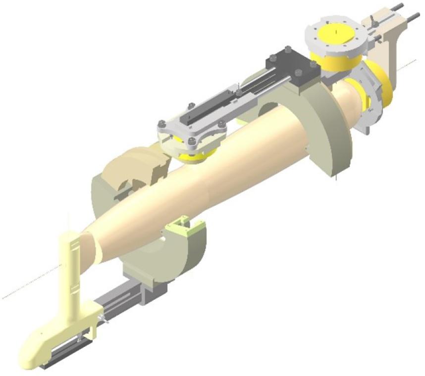
Figure 2.
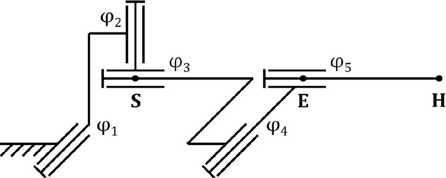
Figure 3.
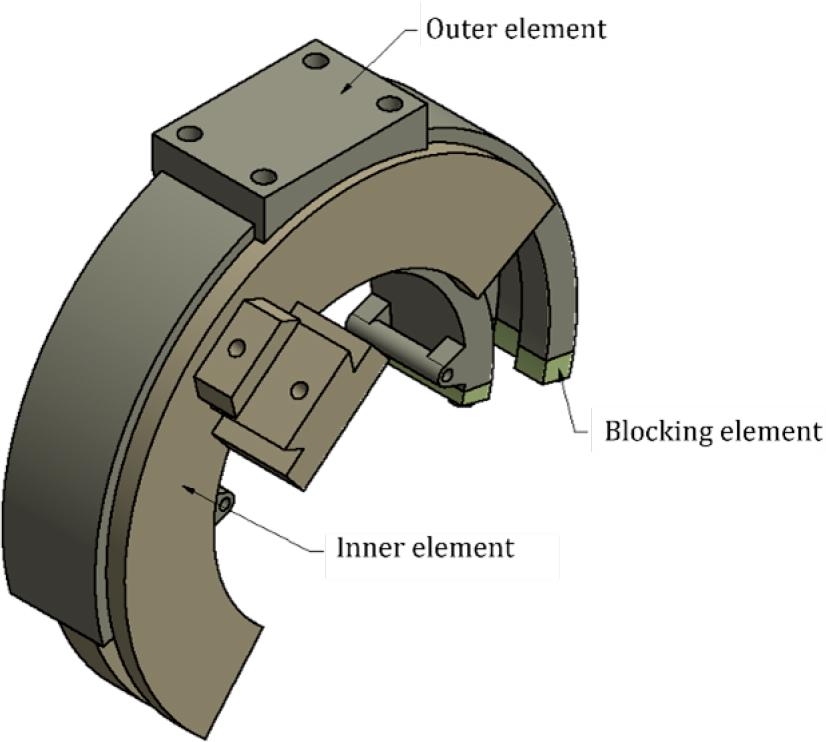
Figure 4.
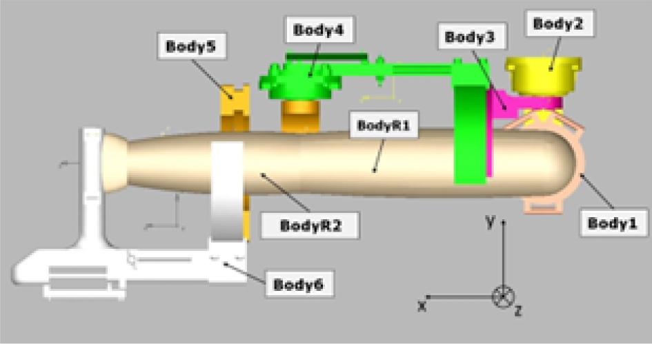
Figure 5.
Figure 6.
Figure 7.
Figure 8.
Figure 9.
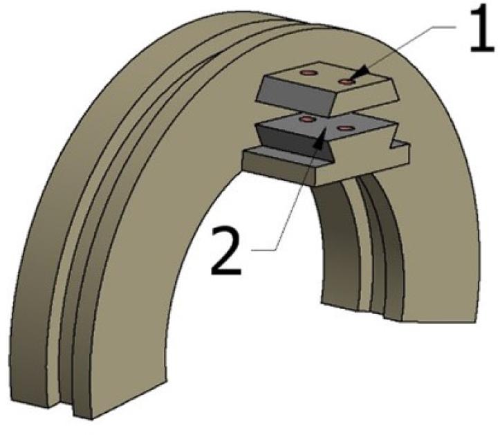
Figure 10.
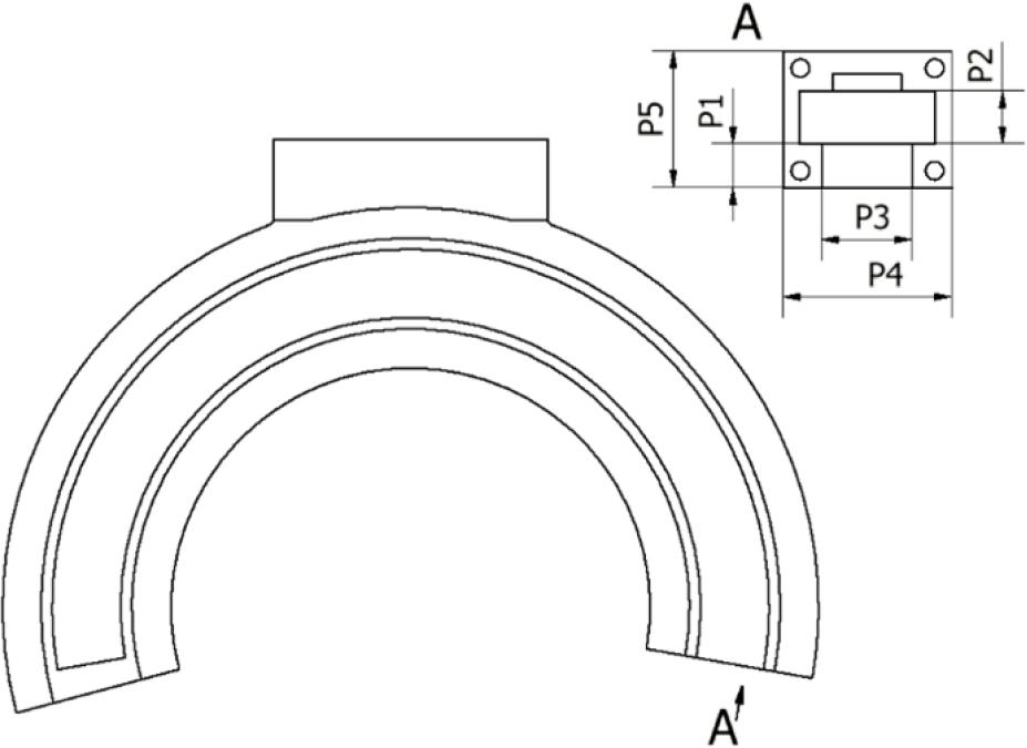
Figure 11.

Figure 12.
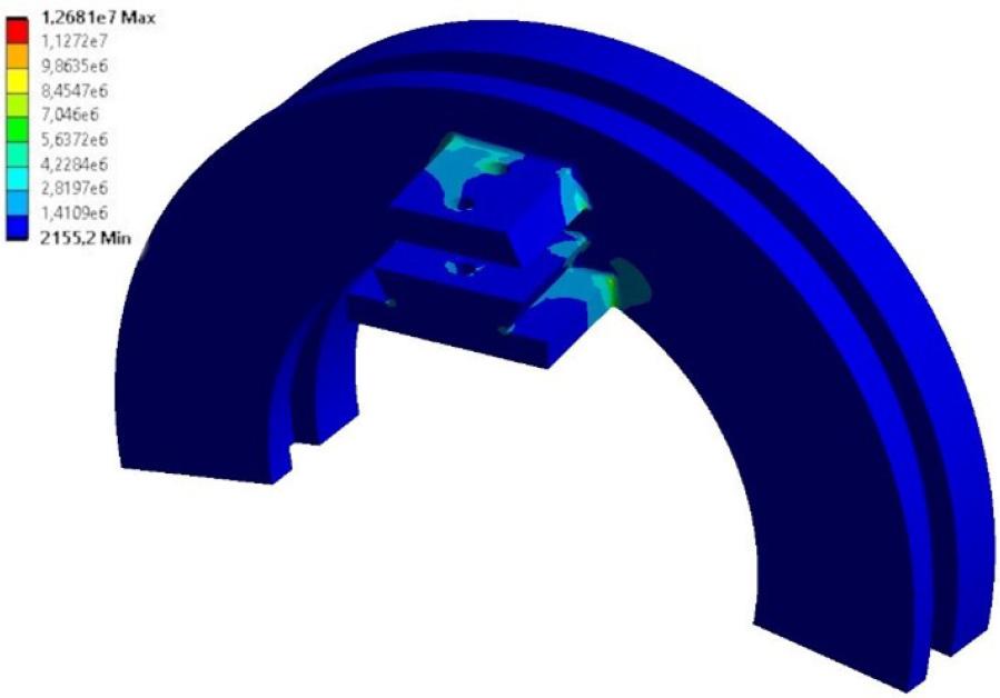
Figure 13.
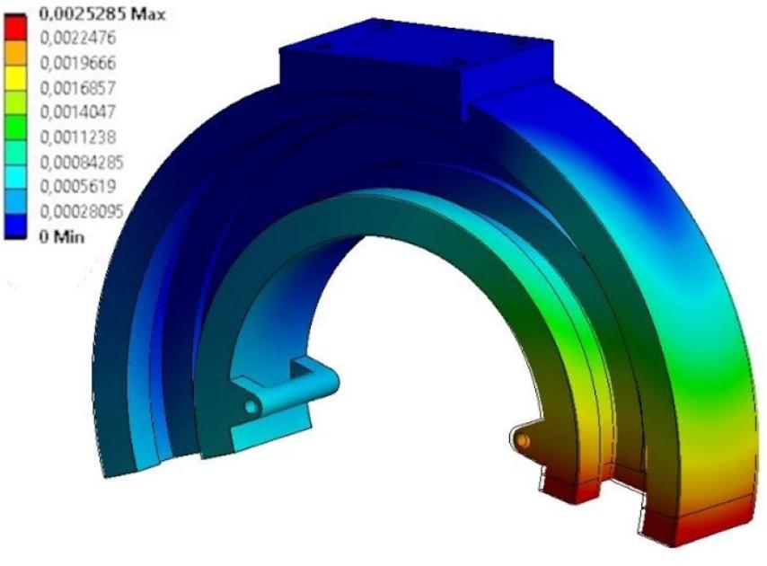
Figure 14.
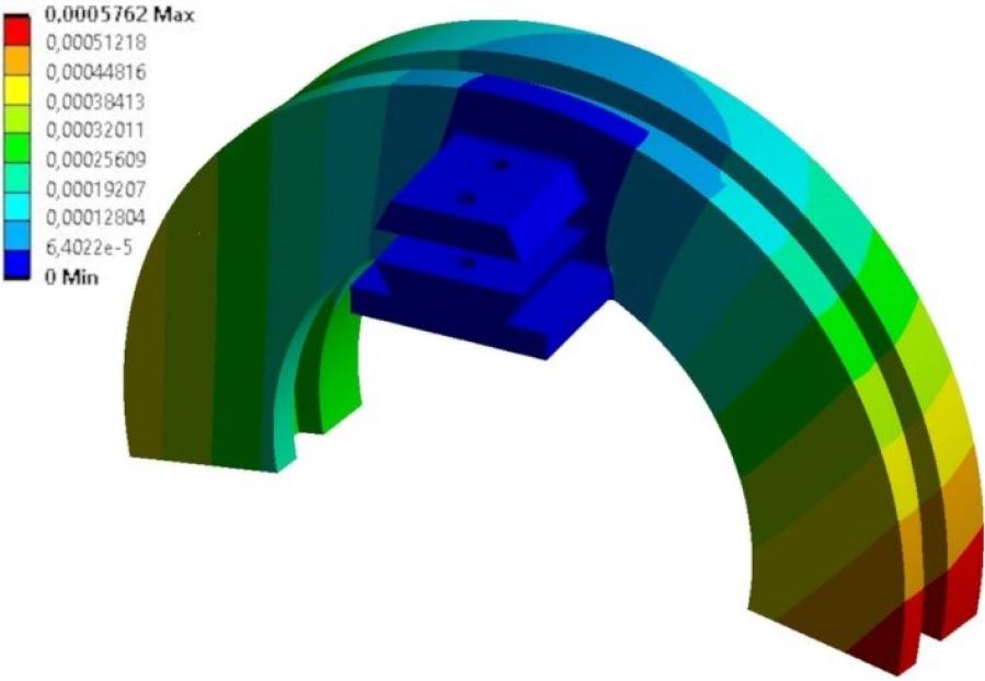
Figure 15.
Figure 16.
Figure 17.
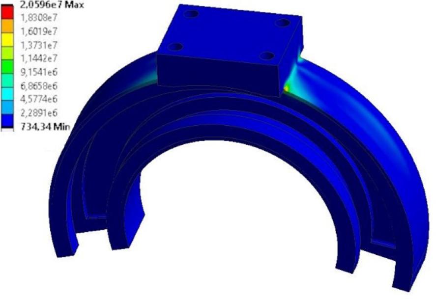
Figure 18.
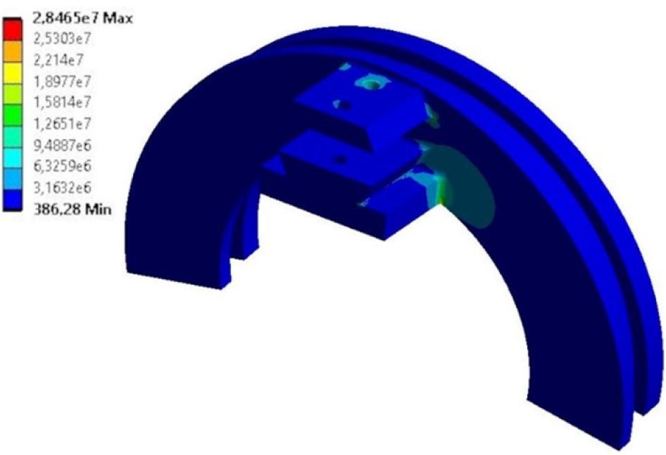
Figure 19.
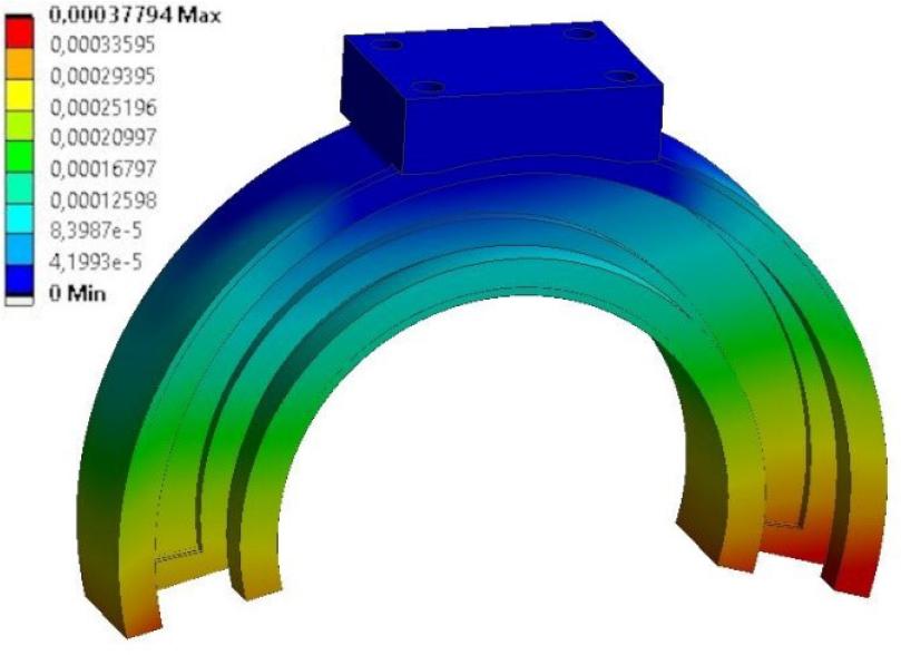
Figure 20.
Considered ranges or discrete values of FEM model parameters
| P1 [mm] | 10 – 16 |
| P2 [mm] | 15 – 20 |
| P3 [mm] | 26 – 30 |
| P4 [mm] | 48 – 60 |
| P5 [mm] | 40 – 50 |
| Material model | Iglidur I190-PF/F3D NanoCarbon |
Maximum angular velocities which may occur in DOFs
| DOF | ωmax [rpm] |
|---|---|
| φ1 | 23.33 |
| φ2 | 21.67 |
| φ3 | 21.67 |
| φ4 | 23.33 |
| φ5 | 13.33 |
Parameters of finite element models for validation of the design
| Element | No. of elements | No. of nodes |
|---|---|---|
| Inner part | 658,387 | 1,018,928 |
| Outer part | 211,159 | 360,405 |
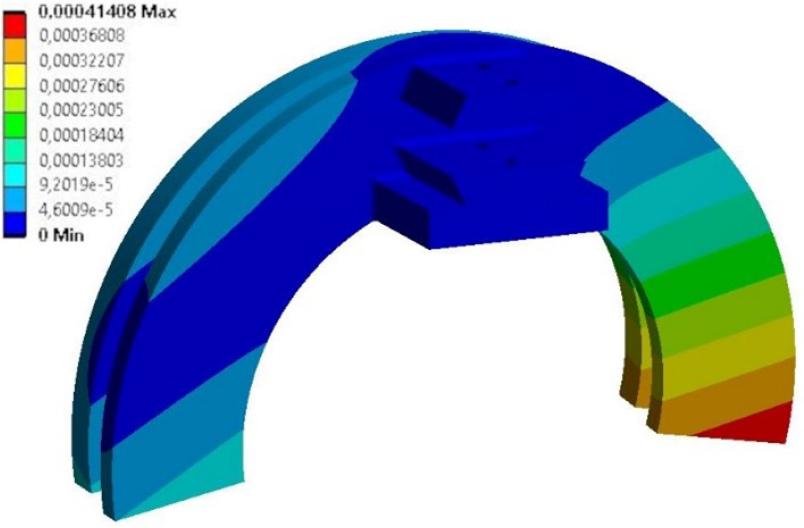
FEM analysis summary after final design modifications
| Element | Outer | Inner |
| Max. stress for sliding element [MPa] | 6.24 | 12.49 |
| Max. stress for main element [MPa] | 20.59 | 28.50 |
| Max. displacement [mm] | 0.38 | 0.41 |
| Max. cylindrical displacement [mm] | 0.10 | 0.08 |
| Max. back surface displacement [mm] | 0.12 | – |
| Min. safety factor | 4.37 | 2.18 |
| Part with the lowest safety factor | Sliding | Sliding |
Coordinates of COMs (centers of masses) of the elements in the local coordinate systems (COMq – center of mass along q axis)
| Body | COMx | COMy | COMz |
|---|---|---|---|
| [mm] | [mm] | [mm] | |
| 1 | 1013.4 | 918.0 | 1369.0 |
| 2 | 6705.0 | 5734.0 | 2448.2 |
| 3 | 6553.9 | 6196.3 | 2614.4 |
| 4 | 10605.0 | 38714.7 | 37689.3 |
| 5 | 7627.1 | 3805.2 | 8066.9 |
| 6 | 11756.7 | 23986.1 | 25468.9 |
| R1 | 413000.0 | 1861000.0 | 2011000.0 |
| R2 | 345000.0 | 1504809.0 | 1312510.0 |
Parameters of finite elements models
| Element | No. of elements | No. of nodes |
|---|---|---|
| Inner part | 161,215 | 240,101 |
| Outer part | 108,993 | 171,687 |
Material properties for FEM analysis
| Material | Iglidur I190-PF | F3D NanoCarbon (PA12 + CF) |
|---|---|---|
| E [GPa] | 1.66 | 6.02 |
| v | 0.306 | 0.306 |
| Yield strength [MPa] | 27.25 | 98.79 |
| Tensile strength [MPa] | 36.06 | 130.73 |
Mass parameters of the multibody model bodies (Iqq – main inertia moment along q axis)
| Body | Mass | Ixx | Iyy | Izz |
|---|---|---|---|---|
| [kg] | [kg · mm2] | [kg · mm2] | [kg · mm2] | |
| 1 | 0.9 | 1013.4 | 918.0 | 1369.0 |
| 2 | 1.3 | 6705.0 | 5734.0 | 2448.2 |
| 3 | 1.1 | 6553.9 | 6196.3 | 2614.4 |
| 4 | 2.0 | 10605.0 | 38714.7 | 37689.3 |
| 5 | 1.2 | 7627.1 | 3805.2 | 8066.9 |
| 6 | 1.6 | 11756.7 | 23986.1 | 25468.9 |
| R1 | 3.0 | 413000.0 | 1861000.0 | 2011000.0 |
| R2 | 2.5 | 345000.0 | 1504809.0 | 1312510.0 |
Equivalent load states for the considered combinations of bearing arrangements (DOF column represents the DOF for which the parameters are presented with the configuration in the open bearing by the rotation in degrees, Fq – force along q axis of the global coordinate system, Mq – force along q axis of the global coordinate system)
| Case | DOF | My [Nm] | Mz [Nm] | Fx [N] | Fy [N] | Fz [N] |
|---|---|---|---|---|---|---|
| 1 | φ3 = —90° | -22.91 | 42.41 | -411.78 | 14.00 | 0.67 |
| φ5 = —90° | -2.82 | -29.45 | -96.72 | 184.97 | 50.72 | |
| 2 | φ3 = —90° | 21.08 | 42.02 | -406.91 | 13.77 | 0.73 |
| φ5 = 0° | 2.39 | -3.83 | -47.23 | 148.78 | 51.64 | |
| 3 | φ3 = —90° | -22.63 | 42.21 | -408.22 | 14.20 | 0.58 |
| φ5 = 90° | 3.15 | -14.59 | -60.37 | 155.04 | 51.96 | |
| 4 | φ3 = 0° | -22.84 | 43.02 | -416.88 | 14.39 | 0.77 |
| φ5 = —90° | -2.18 | 3.00 | -170.39 | 112.58 | 50.51 | |
| 5 | φ3 = 0° | 22.06 | 42.73 | -406.00 | 13.67 | 0.70 |
| φ5 = 0° | 2.28 | -7.38 | 2.52 | 101.64 | 47.46 | |
| 6 | φ3 = 0° | -22.65 | 43.18 | -405.62 | 14.24 | 0.63 |
| φ5 = 90° | 2.98 | 1.83 | -153.83 | 117.94 | 46.60 | |
| 7 | φ3 = 90° | 21.03 | 41.05 | -406.34 | 13.58 | 0.71 |
| φ5 = 0° | 1.94 | -4.11 | -57.71 | 130.76 | 52.62 | |
| 8 | φ3 = 90° | -22.79 | 42.68 | -413.80 | 14.04 | 0.71 |
| φ5 = —90° | 1.06 | -6.76 | 48.09 | 129.60 | 55.34 | |
| 9 | φ3 = 90° | -22.05 | 42.62 | -409.69 | 13.63 | 0.55 |
| φ5 = 90° | 2.57 | -5.47 | -148.67 | 115.31 | 51.36 |
FEM model parameters initial values (input parameters: P1-P5 and Material model, output parameters: maximum stresses and masses of the parts)
| P1 [mm] | 15.0 |
| P2 [mm] | 20.0 |
| P3 [mm] | 30.0 |
| P4 [mm] | 60.0 |
| P5 [mm] | 50.0 |
| Material model | Iglidur I190-PF |
| Max stress in inner part [MPa] | 12.68 |
| Max stress in outer part [MPa] | 9.49 |
| Inner part mass [kg] | 0.96 |
| Outer part mass [kg] | 0.85 |
FEM model parameters final values (input parameters: P1-P5 and Material model, output parameters: maximum stresses and masses of the parts)
| P1 [mm] | 12.8 |
| P2 [mm] | 15.5 |
| P3 [mm] | 26.5 |
| P4 [mm] | 49.3 |
| P5 [mm] | 40 |
| Material model | NanoCarbon (PA 12 + CF) |
| Max stress in inner part [MPa] | 12.9 |
| Max stress in outer part [MPa] | 25.6 |
| Inner part mass [kg] | 0.61 |
| Outer part mass [kg] | 0.48 |