
Exoskeletons are a group of wearable robots that serve as human external exoskeletons. Hence, they are able to support users with additional force or even fully bring back the motion capabilities. They are distinguished by their kinematic chain mapping on the human limb anatomy. These devices combine sensory and control technologies, among others, and exhibit features of bionics, robotics, computer and control science, medicine, and other interdisciplinary fields [35]. They support the work of a single or several segments of a user. Due to the kinematics corresponding to that of the human limb, exoskeletons make it possible to precisely apply the required torque to a specific joint of the user [27].
Exoskeletons can serve different functions depending on the field in which they are applied.
The most common purposes of the exoskeleton’s intraction with the user are power amplification, assistance and motor function substitution. Due to these devices’ wide range of applicability, they have been found to be used in fields such as the military, rehabilitation, and industry [5,19,20,31]. Robotic systems, such as exoskeletons, find increasing use in rehabilitation with similar or marginally superior results compared to the standard rehabilitation performed by the physiotherapist [33].
An essential part of the exoskeleton design is its number of Degrees of Freedom (DOFs). Devices with DOF numbers closer to those of the limb they support enable users to achieve more complex and natural movements. However, this requires more complex control algorithms [32] and a higher manufacturing cost for such a device.
For fully wearable exoskeletons to be as comforTable as possible, it is necessary to reduce the weight exerted on the user [36]. In the case of full-body and lower-limb exoskeletons, it is possible to compensate for the weight of the exoskeleton by using appropriate actuators. On the other hand, research indicates that such structures’ greater moment of inertia [21] may affect the user’s comfort.
However, total weight compensation is not always possible in upper limb exoskeletons, primarily when the entire weight rests on the user. The greater weight of the exoskeleton, in addition to the potential discomfort of use, is often associated with greater energy consumption relative to lighter designs, which, in the case of the lower limb and full-body exoskeletons, may impact their range [12].
In exoskeletons, a large proportion of the mass is accounted for by the weight of the actuators. In typical designs, a higher number of DOFs often goes hand in hand with a higher weight of the whole device. This results in a need to balance the number of DOFs when designing an exoskeleton so that it is not too heavy while allowing the required range of motion, also for patients with reduced mobility [30].
One of the main design challenges for exoskeletons is to reduce their mass without restraining the mobility of the mechanism. The mass of the devices typically increases significantly with the number of actuators and their power [16]. Hence, it results in lighter exoskeletons having fewer degrees of freedom. However, this approach leads to limiting the exoskeleton’s functionality.
In some solutions, where the device is intended to assist with a single specific type of movement, this may not necessarily be a big problem. On the contrary, the situation is different for the devices used for a wide range of motion patterns by multiple people [29]. One such application is robot-aided rehabilitation.
Reducing the mass of the devices while maintaining their mobility is possible by using free degrees of freedom in their kinematics (passive joints). These are movable only with the user’s force. Thus, they reduce the number of actuators in the structure. For such an approach, free DOFs should be the ones requiring relatively small torque to be driven (this should be significantly lower than possible to be generated by a user in a certain DOF). Moreover, the construction should have a relatively low moment of inertia regarding the corresponding axis of rotation [11].
The use of free degrees of freedom in the device’s kinematics will necessitate predictive control. This is caused by the inability to control such DOFs. Therefore, realizing the tasks requires compensating their configuration by other DOFs. Such can benefit from involving AI (Artificial Intelligence) to predict the user’s movements [15]. The algorithms are typically based on information about the movement in the free degrees of freedom. Nevertheless, they can be enhanced by introducing EMG measurements, reflecting the muscular activity of a user [23].
Additive manufacturing technologies noted rapid development in recent years [40]. They allow the manufacturing of complex geometries, often impossible to obtain with subtractive manufacturing techniques. Moreover, additive techniques are suiTable for small batch production, thus allowing user-specific designs to be manufactured at relatively low cost [3]. This corresponds to the need for device-aided personalized medicine. Especially for the patients significantly differing with anatomy [9].
Additive manufacturing technologies have been applied in the manufacture of exoskeletons [6]. Two techniques are particularly usable – FFF/FDM (Fused Filament Fabrication / Fused Deposition Modeling) printing for plastics [24] and SLS printing technology for powders of plastics or metals [22].
FFF/FDM printing is the most common additive manufacturing technology. It is based on the extrusion of semi-fluid thermoplastic material so that it is arranged in interconnected pathways, forming layers that, when superimposed on one another, create geometry [38]. Models produced with the FFF technology often find use in rapid prototyping processes and the production of personalized components for a specific user. It is due to the relatively low cost of unit production [13]. Thanks to the recent dynamic development of this technology, many materials with different strength parameters and physical properties are available on the market [28, 34]. However, this technology has several limitations, which must be considered when designing medical elements.
The manufactured components can be brittle and do not behave in the isotropic way [10, 39]. Therefore, the design process for such parts should include their strength simulations. An increase in the use of this technology in the medical industry to produce prototypes of medical devices and components, such as dedicated orthoses, has been observed in recent years [26].
SLS (selective laser sintering) printing is a technology based on bonding powders with a laser beam [4]. As in FFF/FDM printing, the parts made using this technology are made layer by layer. Apart from thermoplastic materials in the form of powder, metals and ceramics can be used as well [25]. The geometries obtained with this technology usually have a better external surface quality than those obtained with FFF/FDM technology. Their mechanical properties are orthotropic [8], but for some cases, they are very close to isotropic.
Free degrees of freedom in exoskeletons can be realized mechanically by using bearings. However, with the standard bearings, allowing 360 degrees of rotation may negatively affect the device’s convenience, especially during attaching to the patient’s extremities. With the enclosed bearings, a user must put their body segments through these along the kine-matic chain of the device. Hence, patients with spastic contractions or affected anatomy can be unable to use such systems. Therefore, it is advantageous to introduce bearings with a semi-open design that allows rotation in the free degrees of freedom by an angle corresponding to the anatomical human range of motion. As the solution blocks excessive rotation of the device in free DOFs (beyond the user’s anatomical joint rotation range), it improves the safety of the exoskeleton. In addition, such a design can incorporate features that allow the exoskeleton to be mounted on the user, strap or velcro holders, and soft padding, among others.
Such a bearing should consist of two main relatively sliding cooperating components. It must be lightweight and strong and the same time. As the design is not enclosed, the rolling elements between the two main components cannot be used. For this reason, the surfaces remaining in contact should be made of sliding materials that are durable to wear.
Additive technologies can be used to manufacture such bearings. Their use may allow obtaining geometries that would be difficult or impossible to produce with other technologies. Such can be the results of numerical optimization targeting overall mass reduction while still meeting the strength and functional requirements.
The study aims to present the design process of the innovative open bearings to be used within the exoskeletons supporting human activities. The process consists of anthropometric modelling, mechanical design, parametric optimization, and strength validation. The bearings presented in the paper are dedicated to the rehabilitation device, ExoReha [14, 15].
The outcomes of the works were manufactured and implemented in the design. However, such structures and their design methodology are applicable to other devices, such as end-effector rehabilitation robots with exoskeleton-like attachments of the effectors or assistive robots for supporting activities of daily living.
The model preparation and optimization process will proceed in the following order (unless noted otherwise, Autodesk Inventor Professional 2021 was used for CAD modelling, MSC Adams 2021.1 – for dynamic analysis, and Ansys 2021 R1 – for FEA analysis and optimization):
- -
Preparation of a CAD model of the exoskeleton based on the developed kinematics and anthropometric data,
- -
Preparation of a simplified six-body model of the exoskeleton, with solids consisting of rigidly connected elements,
- -
Dynamic analysis to obtain equivalent forces and moments occurring in the bearings for three critical positions of each bearing,
- -
Preparation of a fully functional geometrical model of the bearing for finite element analysis in the SpaceClaim module of Ansys 2021 R1 software,
- -
Preparation of the FEA model with high-quality finite element mesh and loads reflecting the most dangerous cases from the dynamic simulation,
- -
Strength validation of the model in different configurations of the bearing components relative rotation,
- -
Numerical parametric optimization of the model under the most dangerous load cases.
- -
Redesigning of the bearing based on the optimization results to meet the functional criteria,
- -
Strength validation of the final model.
Within the framework of this paper, the free degrees of freedom corresponding to the anatomical movements of the upper extremity will be considered. The analogical method can also be used for lower limb exoskeletons with free degrees of freedom.
The concept of using free degrees of freedom in exoskeleton kinematics through the use of open bearings is used in the „ExoReha” exoskeleton (CAD model is shown in Figure 1), which is a device used for task-oriented therapy of the upper extremity [14, 15, 17, 18]. It is dedicated to rehabilitating post-stroke, neurological, orthopaedic, post-accident and post-surgical patients. The kinematics of the device (presented in Figure 2) consists of five degrees of freedom, three of which are driven (DOFs corresponding to the angles marked as φ1, φ2, and φ4, in Figure 2).The two remaining ones (DOFs corresponding to the angles labelled as φ3 and φ5 in Figure 2), corresponding to shoulder and elbow joint rotations, remain non-driven.
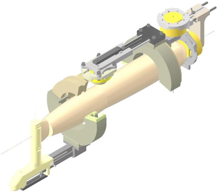
CAD model of the ExoReha upper extremity exoskeleton
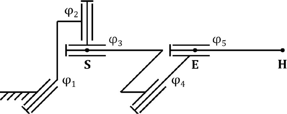
ExoReha kinematics model
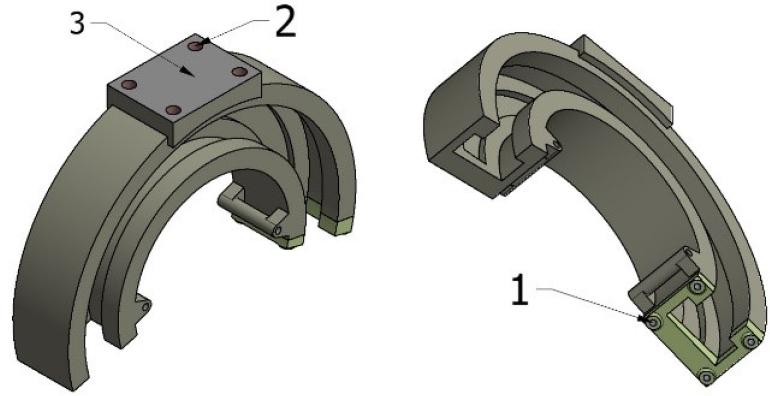
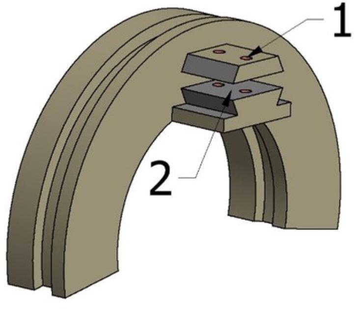
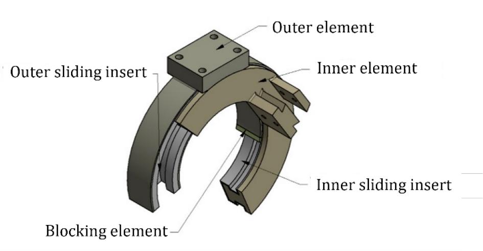
Preliminary geometrical models of the open bearings have been designed as shown in Figure 3. They consist of an inner and outer part, slidingly relatively, and a locking element to enclose the bearing inner element inside the outer and block excessive rotation. All of them are initially designed as monoliths made of sliding material (3D-printed from Iglidur I-190-PF).
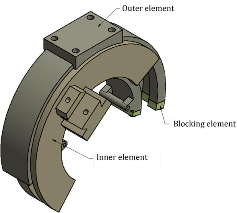
Initial open bearing design
The other exoskeleton components are mounted to the bearings with screw connections – with the thru holes in the inner part and metal inserts melted into the outer part. Moreover, the locking part is assembled into the metal inserts placed in the outer element.
Therefore, in the following analysis, it is treated as its integral part. The outer part of the bearing is designed to allow the user’s extremity attachment using the straps with buckles.
The prepared model has then undergone strength analysis and parametric optimization to reduce its weight. In the following sections, the bearing design process is presented on the example of the DOF φ3 shown in Figure 3. Nevertheless, the process was analogically conducted for the DOF φ5.
The dynamic analysis of the exoskeleton was carried out to determine the resultant forces acting on the bearings during operation. The multibody model used for this process is visualized in Figure 4. It is worth noticing that the ExoReha exoskeleton has an adjustment, allowing to fit a user with anatomical parameters between the ones for the 5th female percentile of the Polish population [7] (denoted hereafter as W5) and the 95th male centile of the Polish population (denoted hereafter as M95). The model chosen for the dynamic analysis corresponds to the configuration of the device adapted to the M95 user, as it will cause the greatest possible reaction forces. The multibody model includes the upper extremity model attached to the exoskeleton in the mounting points of the bearings. The model shown in Figure 4 is a geometrically modified CAD model of the device, in which rigidly connected components have been simplified to individual solids. The upper extremity model consists of two solid elements: one corresponding to the arm and a one corresponding to the combined forearm with the hand.
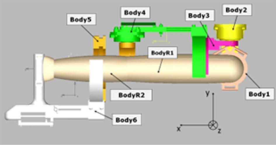
Exoskeleton multibody model for dynamics analysis
All the bodies have individual parameters assigned – masses, moments of inertia with respect to the rotational axes of the solids (axes as shown in Figure 4), and the centers of mass (COMs). These are presented in Tables 1 and 2. For the exoskeleton model, these data were calculated numerically based on the density of the materials within Autodesk Inventor Professional 2021 software. The data for the extremity submodels come directly from the anthropometric Tables or were calculated based on them. The multibody model has five degrees of freedom. Hinge joints were used to connect the bodies of the exoskeleton as in real life.
Mass parameters of the multibody model bodies (Iqq – main inertia moment along q axis)
| Body | Mass | Ixx | Iyy | Izz |
|---|---|---|---|---|
| [kg] | [kg · mm2] | [kg · mm2] | [kg · mm2] | |
| 1 | 0.9 | 1013.4 | 918.0 | 1369.0 |
| 2 | 1.3 | 6705.0 | 5734.0 | 2448.2 |
| 3 | 1.1 | 6553.9 | 6196.3 | 2614.4 |
| 4 | 2.0 | 10605.0 | 38714.7 | 37689.3 |
| 5 | 1.2 | 7627.1 | 3805.2 | 8066.9 |
| 6 | 1.6 | 11756.7 | 23986.1 | 25468.9 |
| R1 | 3.0 | 413000.0 | 1861000.0 | 2011000.0 |
| R2 | 2.5 | 345000.0 | 1504809.0 | 1312510.0 |
Coordinates of COMs (centers of masses) of the elements in the local coordinate systems (COMq – center of mass along q axis)
| Body | COMx | COMy | COMz |
|---|---|---|---|
| [mm] | [mm] | [mm] | |
| 1 | 1013.4 | 918.0 | 1369.0 |
| 2 | 6705.0 | 5734.0 | 2448.2 |
| 3 | 6553.9 | 6196.3 | 2614.4 |
| 4 | 10605.0 | 38714.7 | 37689.3 |
| 5 | 7627.1 | 3805.2 | 8066.9 |
| 6 | 11756.7 | 23986.1 | 25468.9 |
| R1 | 413000.0 | 1861000.0 | 2011000.0 |
| R2 | 345000.0 | 1504809.0 | 1312510.0 |
Spherical joints were used to connect the upper extremity bodies to one another and to the ground element. In addition, one degree of freedom was taken away from the modelled elbow joint. The exoskeleton was connected to the extremity model at three points using “lock” joints (which take away the possibility of relative movement of connected elements): at the point of contact between the hand and the handle and at the centers of bearings with the arm and forearm. The former represents grasping the device handle, while the latter represents attachment of the structure by straps.
For the analysis, it was assumed that the highest forces and moments acting upon the open bearings occur when the following conditions occur:
- -
the exoskeleton is in the stretched (base) configuration (shown in Figure 4);
- -
every DOF is rotating with the maximum possible velocity;
- -
all the drives act with maximum torque in directions opposite to the movement in the corresponding DOFs.
The Earth’s gravitational acceleration was set along the negative Y-axis (see Figure 4). The angular velocities set for the joints are presented in 3. Their directions are as for the lifting task. These assumptions guarantee that the forces occurring within rehabilitating individuals with ExoReha will not exceed the calculated ones, regardless of the activity being performed.
Maximum angular velocities which may occur in DOFs
| DOF | ωmax [rpm] |
|---|---|
| φ1 | 23.33 |
| φ2 | 21.67 |
| φ3 | 21.67 |
| φ4 | 23.33 |
| φ5 | 13.33 |
The forces and moments acting in the bearing were determined for the three configurations presented in Figure 5. These correspond to the two extreme bearing swings (±90 degrees from the axis of symmetry) and the position at the center of the range of motion (at the axis of symmetry of the bearing).
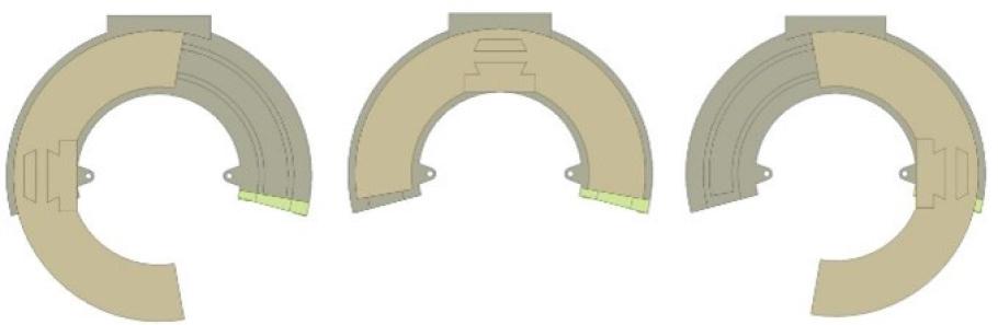
Analyzed bearing configurations; from left: -90 deg, 0 deg, and 90 deg
Only the first step of the simulation was considered for further analysis, as only therein was the exoskeleton in the characteristic configuration. To find the most severe load, only the most dangerous load case was used for the strength analysis.
For further strength analysis, geometries of the two interfacing bearing parts were prepared in the SpaceClaim environment based on their initial models. They are visualized in 6 and 7.
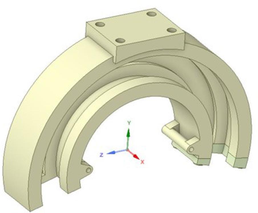
The outer part geometry prepared in the SpaceClaim
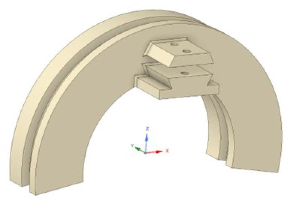
The inner part geometry prepared in the SpaceClaim
Based on the geometry, element meshes were prepared for these. Different mesh grids were tested, and the ones with the best minimal element quality indicators were selected. Their parameters are presented in Table 4. The final mesh grids were constructed using mainly tetrahedral elements.
Parameters of finite elements models
| Element | No. of elements | No. of nodes |
|---|---|---|
| Inner part | 161,215 | 240,101 |
| Outer part | 108,993 | 171,687 |
The mesh grids’ quality was assessed as high using the ”element quality” criterion, embedded into Ansys 2021 R1, and calculated according to the formula 1, where the following symbol state for the variables:
- -
EQ – element quality,
- -
c – constant for the element type,
- -
V – element volume,
- -
li – the length of i-th element’s edge.
The outcome was considered satisfactory when there were no elements with a quality lower than 0.2. The minimum element quality was 0.282 of for the inner part and 0.213 for the outer part, while the average element quality was 0.836 for the inner part and 0.821 for the outer part.
The geometry of the outer part was constrained, as shown in Figure 8, with the corresponding constraints:
- 1)
A bushing-type constraint on the planes, which simulates a bolted connection between the outer part of the bearing and the locking element;
- 2)
Fixed-support-type constraints set on the cylindrical surfaces of the holes, restraining their movements and deformation, which simulate the screw connection of the outer part with the next part of the exoskeleton (through a non-threaded hole);
- 3)
A “frictionless support” set on the plane, restraining rotation around the axes other than those normal to the plane and the transitional movement in an out-of-plane direction, which simulates contact with the next part of the exoskeleton.
Constraints of the outer part
The geometry of the inner part was constrained, as shown in Figure 9 with the corresponding constraints:
- 1)
Fixed-support-type constraints set on the cylindrical surfaces of the holes, restraining their movements and deformation, which simulate the screw connection of the inner part with the previous part of the exoskeleton (threaded insert);
- 2)
A “frictionless support” set on the plane, restraining rotation around the axes other than those normal to the plane and the transitional movement in an out-of-plane direction, which simulates contact with the previous part of the exoskeleton.
Constraints of the inner part
Following this, a strength analysis was carried out to compute the stresses and deformations under the most dangerous loads. Initially, the geometry was assumed to be made entirely with the FFF printing technology from the Iglidur l190-PF material. As the analysis is intended to validate the strength of the device with the high safety factor, an average isotropic strength characteristic of the material was involved.
This does not implicate any significant impact on the results analysis. Table 5 shows the material models used for Iglidur l190-PF [2] and F3D NanoCarbon (PA12 + CF) [1], considered in the further stages of the design process.
Material properties for FEM analysis
| Material | Iglidur I190-PF | F3D NanoCarbon (PA12 + CF) |
|---|---|---|
| E [GPa] | 1.66 | 6.02 |
| v | 0.306 | 0.306 |
| Yield strength [MPa] | 27.25 | 98.79 |
| Tensile strength [MPa] | 36.06 | 130.73 |
In the next step, the model was subjected to RSO-type parametric optimization. This is intended to select the model’s dimensions and material to reduce the bearing’s mass while maintaining its functional operation (i.e., from the preconceived ranges). The response planes of the Genetic Aggregation” type were created based on 300 points [37]. For the simulation result to meet the design assumptions, it was assumed that the safety factor for the part after optimization could not be less than 1.3.
The dimensions that have been parameterized are marked in Figure 10 as P1–P5. Parameters P1–P3 are common for both parts (inner and outer) within the only fit tolerance differences. Additionally, the material model was set as the discrete parameter. In order to allow easy attachment of the bearing to the user’s arm, the inner diameter dimension remained unchanged at 146 mm.
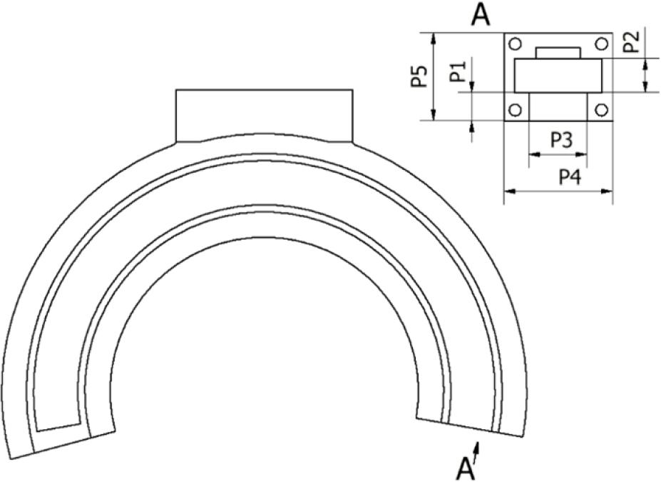
Optimization parameters set
The masses of both bearing parts and the maximum stresses in each were considered the minimized parameters – former with the weight of 1 and latter with the weight of 0.1. Moreover, overshooting the material-dependent maximum average stress divided by the 1.3 safety factor was used as a stop criterion. The initial values of all parameters are presented in Table 6, while their considered ranges are presented in Table 7.
FEM model parameters initial values (input parameters: P1-P5 and Material model, output parameters: maximum stresses and masses of the parts)
| P1 [mm] | 15.0 |
| P2 [mm] | 20.0 |
| P3 [mm] | 30.0 |
| P4 [mm] | 60.0 |
| P5 [mm] | 50.0 |
| Material model | Iglidur I190-PF |
| Max stress in inner part [MPa] | 12.68 |
| Max stress in outer part [MPa] | 9.49 |
| Inner part mass [kg] | 0.96 |
| Outer part mass [kg] | 0.85 |
Considered ranges or discrete values of FEM model parameters
| P1 [mm] | 10 – 16 |
| P2 [mm] | 15 – 20 |
| P3 [mm] | 26 – 30 |
| P4 [mm] | 48 – 60 |
| P5 [mm] | 40 – 50 |
| Material model | Iglidur I190-PF/F3D NanoCarbon |
During the optimization, one of the variable parameters was the material model. This allowed verification of the initial assumption that the bearing parts should be made as sliding monoliths. Perhaps, based on the computations, making them from F3D NanoCarbon (PA 12 + CF) filament with additional sliding elements between the interfacing parts was more beneficial.
The resulting forces and equivalent moments for every free bearings’ configuration are presented in Table 8. Each of the determined load cases can be used for strength analysis. However, based on the computations, the highest stress occurred for load case 4. Hence, it was used for further this simulation and parametric optimization. However, load cases 1 and 8 were also validated as potentially dangerous to the multibody system.
Equivalent load states for the considered combinations of bearing arrangements (DOF column represents the DOF for which the parameters are presented with the configuration in the open bearing by the rotation in degrees, Fq – force along q axis of the global coordinate system, Mq – force along q axis of the global coordinate system)
| Case | DOF | My [Nm] | Mz [Nm] | Fx [N] | Fy [N] | Fz [N] |
|---|---|---|---|---|---|---|
| 1 | φ3 = —90° | -22.91 | 42.41 | -411.78 | 14.00 | 0.67 |
| φ5 = —90° | -2.82 | -29.45 | -96.72 | 184.97 | 50.72 | |
| 2 | φ3 = —90° | 21.08 | 42.02 | -406.91 | 13.77 | 0.73 |
| φ5 = 0° | 2.39 | -3.83 | -47.23 | 148.78 | 51.64 | |
| 3 | φ3 = —90° | -22.63 | 42.21 | -408.22 | 14.20 | 0.58 |
| φ5 = 90° | 3.15 | -14.59 | -60.37 | 155.04 | 51.96 | |
| 4 | φ3 = 0° | -22.84 | 43.02 | -416.88 | 14.39 | 0.77 |
| φ5 = —90° | -2.18 | 3.00 | -170.39 | 112.58 | 50.51 | |
| 5 | φ3 = 0° | 22.06 | 42.73 | -406.00 | 13.67 | 0.70 |
| φ5 = 0° | 2.28 | -7.38 | 2.52 | 101.64 | 47.46 | |
| 6 | φ3 = 0° | -22.65 | 43.18 | -405.62 | 14.24 | 0.63 |
| φ5 = 90° | 2.98 | 1.83 | -153.83 | 117.94 | 46.60 | |
| 7 | φ3 = 90° | 21.03 | 41.05 | -406.34 | 13.58 | 0.71 |
| φ5 = 0° | 1.94 | -4.11 | -57.71 | 130.76 | 52.62 | |
| 8 | φ3 = 90° | -22.79 | 42.68 | -413.80 | 14.04 | 0.71 |
| φ5 = —90° | 1.06 | -6.76 | 48.09 | 129.60 | 55.34 | |
| 9 | φ3 = 90° | -22.05 | 42.62 | -409.69 | 13.63 | 0.55 |
| φ5 = 90° | 2.57 | -5.47 | -148.67 | 115.31 | 51.36 |
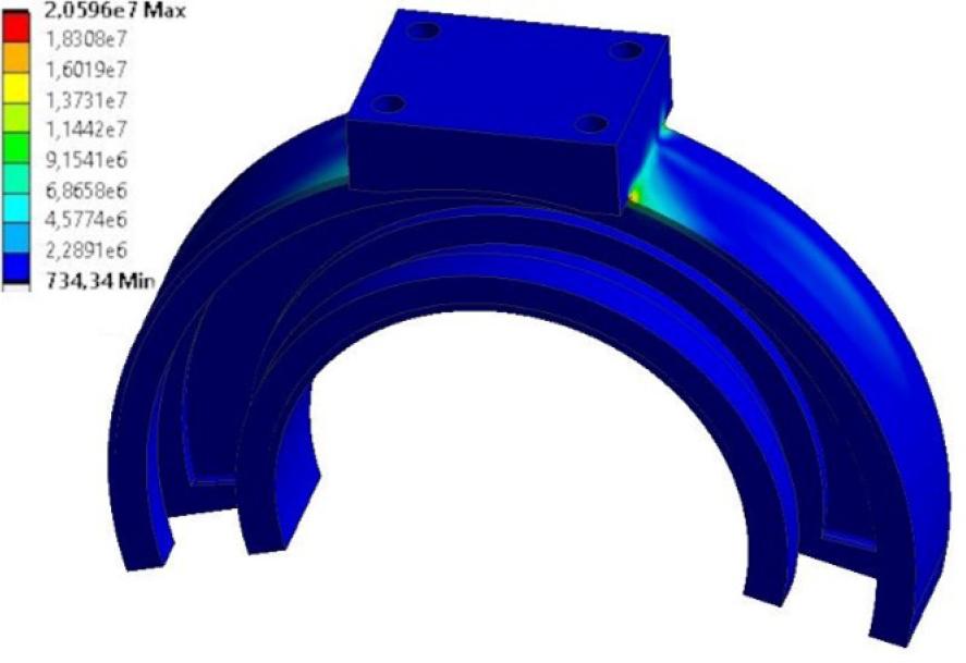
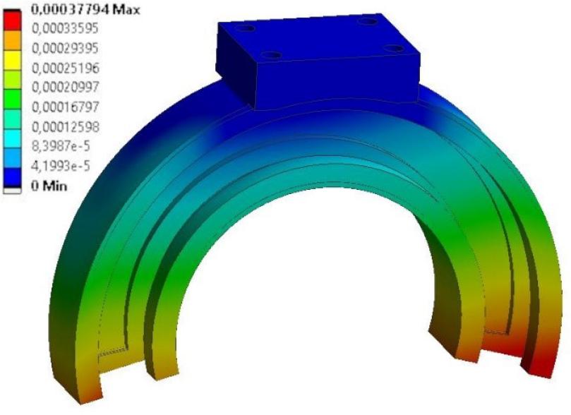
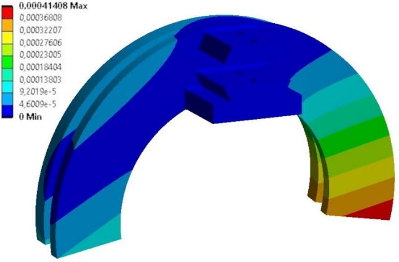
The determined stress distributions in the bearing parts are presented in Figures 11 and 12, while the displacement distributions are visualized in Figures 13 and 14. As expected, the biggest stress appeared in the regions along the edges connecting the cylindrical surfaces of the bearings with the surfaces in contact with the other exoskeleton components. Nevertheless, their maximum values do not cause risks of damaging the design. The biggest total deformations appear in the regions remaining in contact within the configuration – around the locking part. Nevertheless, their values cannot cause blocking the rotation of the bearing.
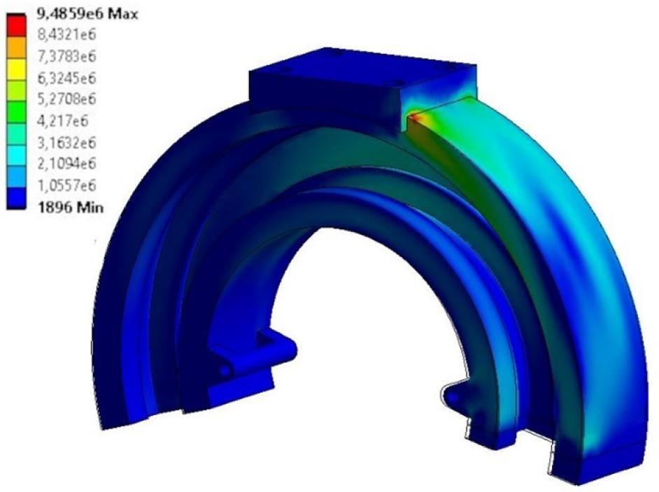
Outer element average stress equivalent distribution
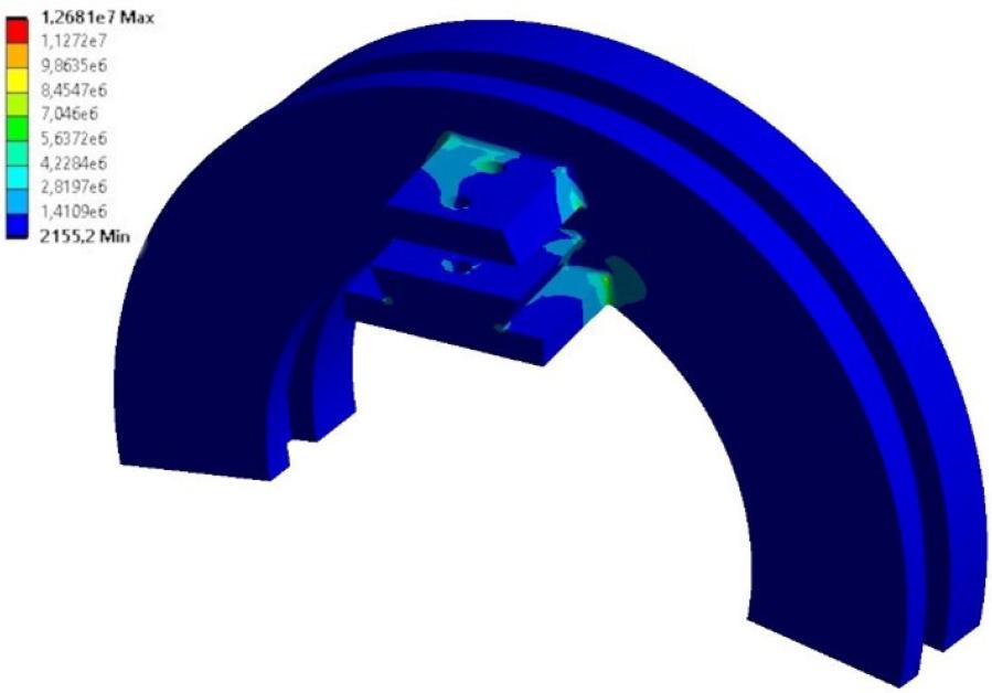
Outer element average stress equivalent distribution
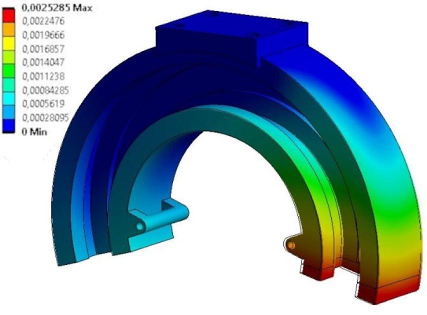
Outer element total deformation distribution
Outer element total deformation distribution
The model obtained as a result of the optimization is compared with the initial design in Figure 15. It is visibly smaller than the original one while meeting the functional and strength criteria. The parameter values obtained as a result of the optimization are shown in Table 9. It is worth noticing that the design material has also been changed as a result of the parametric optimization process.
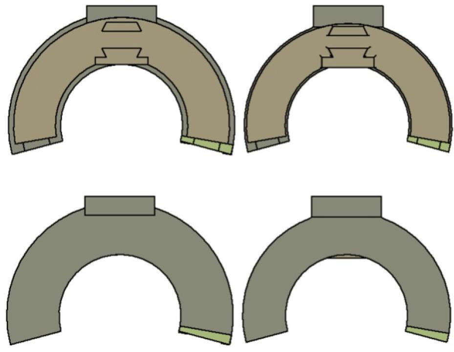
Initial model (left) compared with the model after parametric optimization (right) in the same scale
FEM model parameters final values (input parameters: P1-P5 and Material model, output parameters: maximum stresses and masses of the parts)
| P1 [mm] | 12.8 |
| P2 [mm] | 15.5 |
| P3 [mm] | 26.5 |
| P4 [mm] | 49.3 |
| P5 [mm] | 40 |
| Material model | NanoCarbon (PA 12 + CF) |
| Max stress in inner part [MPa] | 12.9 |
| Max stress in outer part [MPa] | 25.6 |
| Inner part mass [kg] | 0.61 |
| Outer part mass [kg] | 0.48 |
Changing the material significantly reduced the parts’ weight. However, to maintain the functionality of the open bearing, it was necessary to modify the resulting model so that the contact between the bearing parts occurred via sliding elements.
The new model is shown in Figure 16. Two 1-mm width sliding inserts were added between the outer and inner parts, made of Iglidur I190-PF.
Final bearing model
Finite element meshes were again generated for the new bearing model to validate its strength. The parameters of the meshes are collected in Table 10. The quality of all grids was assessed as high using the same “element quality” criterion, where the quality of no element is lower than 0.2.
Parameters of finite element models for validation of the design
| Element | No. of elements | No. of nodes |
|---|---|---|
| Inner part | 658,387 | 1,018,928 |
| Outer part | 211,159 | 360,405 |
The minimum element quality is 0.217 for the inner part and 0.208 for the outer part, while the average element quality is 0.803 for the inner part and 0.819 for the outer part.
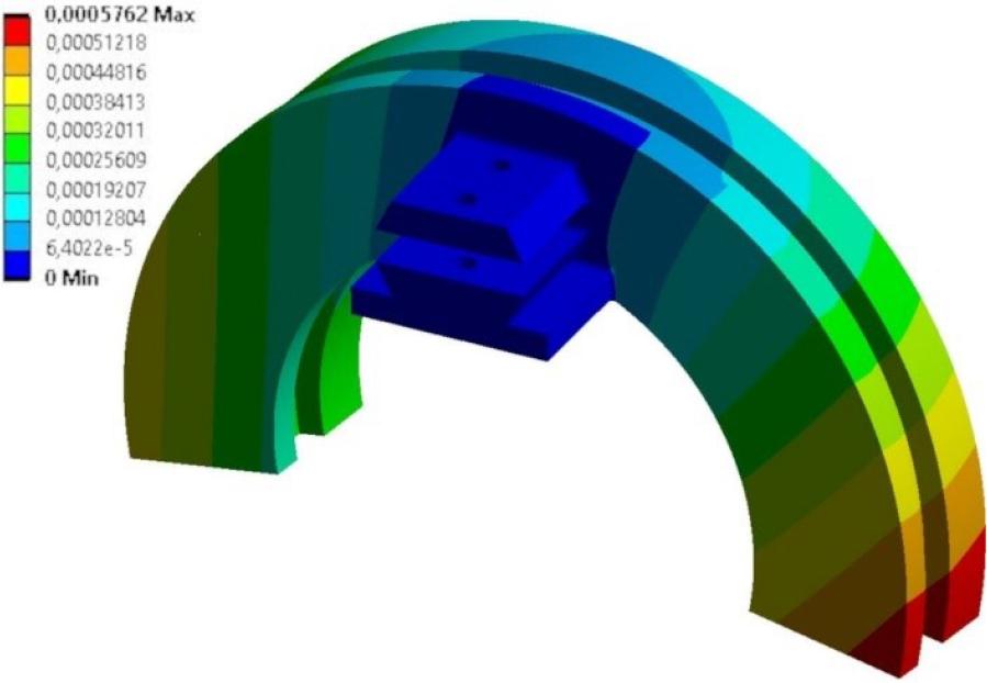
The new model was subjected to analogical strength analysis. Figures 17 and 18 show the stress distributions of the outer and inner parts, respectively, while Figures 19 and 20 present the strain distributions. Table 11 shows maximum values of stress, strain, radial displacements of the sliding cylindrical surfaces, the displacement of the rear surface cooperating with the blocking element in the normal direction (for the outer part), and the minimum safety factor. There is also information on what material the element with the lower safety factor is made of.
Outer element average stress equivalent distribution after parametric optimiation
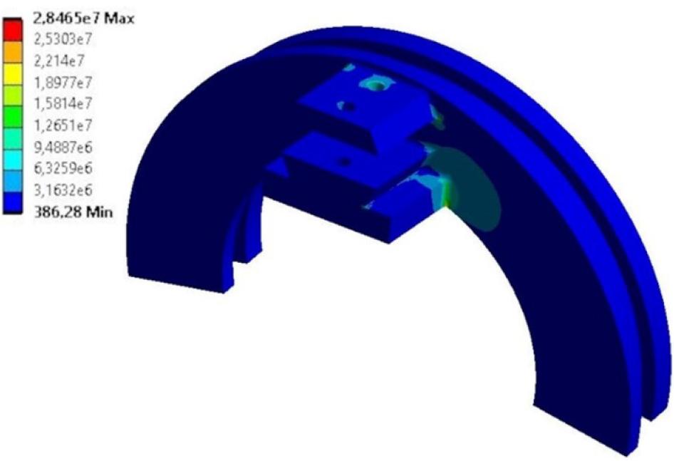
Outer element average stress equivalent distribution after parametric optimiation
Outer element total deformation distribution after parametric optimiation
Outer element total deformation distribution after parametric optimiation
FEM analysis summary after final design modifications
| Element | Outer | Inner |
| Max. stress for sliding element [MPa] | 6.24 | 12.49 |
| Max. stress for main element [MPa] | 20.59 | 28.50 |
| Max. displacement [mm] | 0.38 | 0.41 |
| Max. cylindrical displacement [mm] | 0.10 | 0.08 |
| Max. back surface displacement [mm] | 0.12 | – |
| Min. safety factor | 4.37 | 2.18 |
| Part with the lowest safety factor | Sliding | Sliding |
The stress and deformation distributions remained the same as before the optimization. However, their values increased. However, they do not exceed assumed safe limits and enable safe operation. This includes validating the cylindricality of the inner surfaces of the outer part, and the outer surfaces of the inner part. Similar validation was performed for the components’ interfacing back planes. These deformations are critical, as they can cause stacking restraining rotation of the bearings.
The investigation proved that it is reasonable to design 3D-printed open bearings for assisting robots with the support of numerical optimization. It turned out that powder-based additive manufacturing technologies typically result in a higher strength of the object. However, combining it with FFF/FDM-manufactured thin inserts matches the strength of the construction with the sliding functionality.
The analysis shows that the highest stresses occur in the same regions before and after optimization and for both 3D-printing techniques, along the sharp edges. The determined cylindrical deformations do not exceed the assumed maximum value. The other design assumptions were also met, except for the expected mass reduction. This means that the model has been correctly redesigned, but further optimization can be carried out to reduce its mass, e.g., by using topological optimization. This also confirms that the bearing should not experience excessive wear during operation and that the added sliding insert (made of Iglidur l190-PF with sliding properties and high wear resistance) will work correctly with the rest of the bearing.
It is planned to continue research on possible mass reduction for the presented design with the hybrid optimization approach (multiple parametric and topology optimization cycles) and validate the impact of using average isotropic models instead of the orthotropic one. The designed bearing was 3D-printed with the powder technique and assembled to the “ExoReha” exoskeleton. However, it is planned to further modify the design and reduce the total mass of the exoskeleton by 50%.
The presented methodology is also applicable to the elements designed for conventional manufacturing. Moreover, it is easily transferable to other robots interacting with humans, which require the use of open bearings without drives. These include a wide variety of medical robots, home-use service robots, and even exoskeletons for specific applications.