

Figure 1.
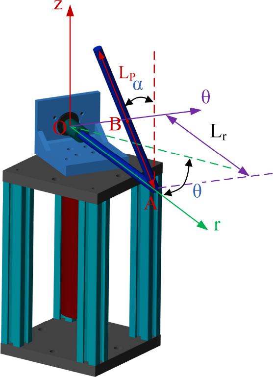
Figure 2.
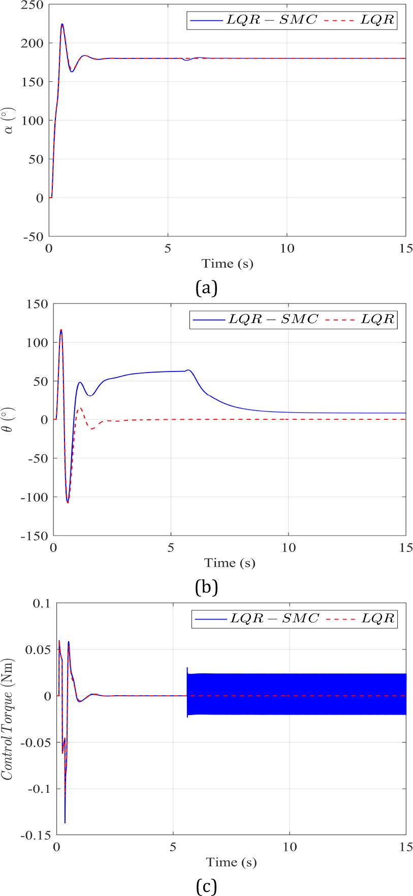
Figure 3.
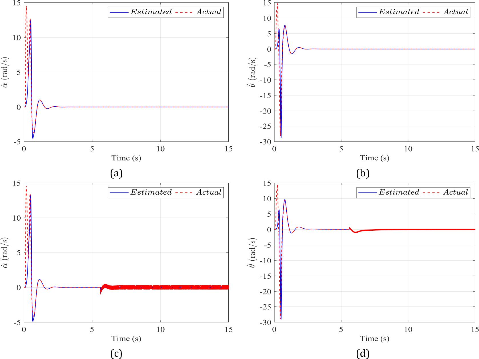
Figure 4.
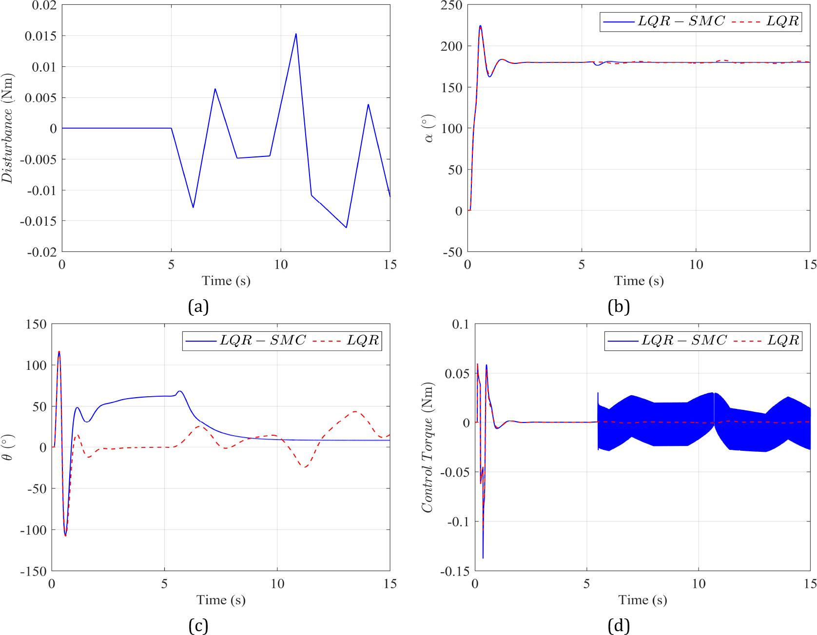
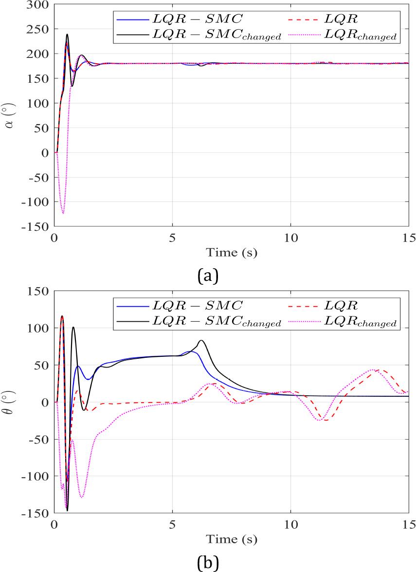
Figure 5.
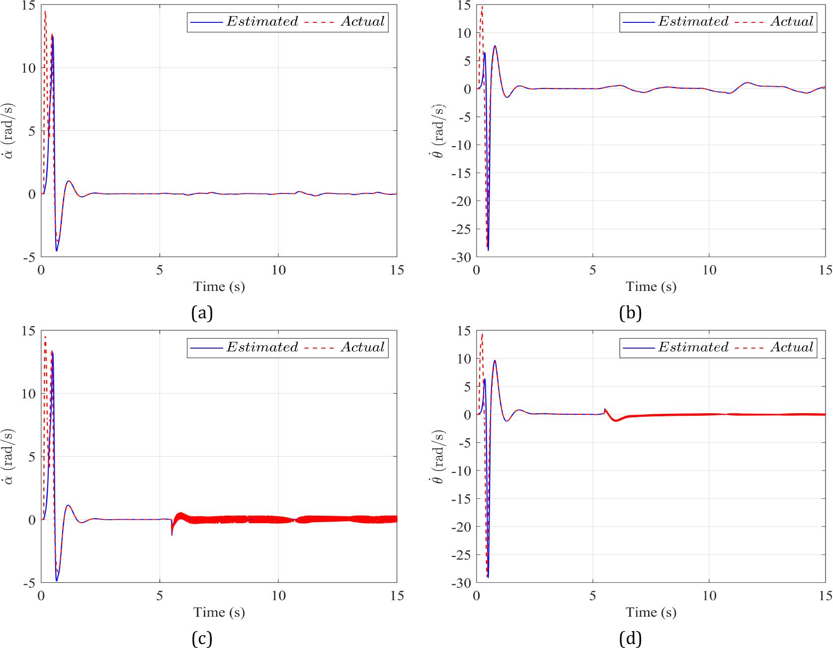
Figure 6.
The parameters of the pendulum_
| Symbol | Description | Values | Units |
|---|---|---|---|
| mp | Pendulum’s mass | 0.125 | kg |
| Lp | Pendulum’s length | 0.15 | m |
| Lr | Rotary arm’s length | 0.15 | m |
| Jp | Pendulum’s inertia moment | 2.3 × 10⁻⁴ | kgm2 |
| Jr | Inertia moment of arm | 9.4 × 10⁻⁴ | kgm2 |
| Bp | Viscous friction coefficient of the pendulum rod | 9.5 × 10⁻³ | - |
| Br | Viscous friction coefficient of the pendulum arm | 0.04 | - |
| Kr | Motor torque constant | 0.042 | Nm/A |
| Km | Motor back EMF constant | 0.042 | Vs/rad |
| Rm | Terminal resistance | 2.6 | Ω |
| Lm | Rotor Inductance | 0.85 | mH |
| g | Gravitational acceleration | 9.81 | m/s2 |