Pose estimation algorithms are a challenging and widely studied research field to estimate pose, motion, and trajectory of target objects. Thanks to recent developments in digital technology, we are able to capture high resolution color images. Nevertheless, depth cameras are more expensive and have lower resolution, although they can acquire 3D point cloud data from the real world that can be used to find poses of objects in 6 degrees of freedom (6-DoF). Pose estimation algorithms are utilized in a wide range of vision applications such as robot navigation, augmented reality (AR), camera calibration, action recognition, and human-machine interaction [1]–[5]. There is no typical method that defines model and target similarity. A variety of methods can be used to calculate poses such as matching image features, point clouds, or deep learning methods. Pose estimation algorithms process model and target frames by using pre-calibrated camera systems and aim to estimate the 6-DoF accurately. Even though many researchers have proposed pose estimation algorithms, these algorithms are still unsolved due to local minima and false matches in real-world applications. Therefore, we have developed an algorithm that presents enhanced pose estimation and a method that calibrates with external camera sensors.
The accuracy of the relative pose can be very important for many real-world applications. Applications include robot vision, autonomous vehicles that are subject to noise and outliers, so that outliers can be eliminated to find accurate estimation. A robot in a spacecraft needs to complete active debris removal tasks in space, micro robot arms are utilized for medical operations that require high accuracy and sensitivity, autonomous vehicles drive passengers and are required to estimate the relative pose of nearby vehicles [6].
Our proposed algorithm finds and fuses the depth and flow measurements captured by the Kinect II. The relative pose is compared with the ground truth for evaluation. Microsoft Kinect II created a great impact on the computer vision and deep learning field, which provides RGB-D imaging and rough pose estimates for indoor scenarios. Raw RGB-D images are acquired by the Kinect II, which is released for gaming and presents an inexpensive and commercial human motion capture device, released to the market in 2014.
The rigid object pose defines finding the best alignment of the model and the target object image. The rigid transformation of an object can be quantified in terms of R and T. Color image-based methods propose pose estimations limited to 2D, depth can be used to upgrade estimation to higher dimensions. However, depth cameras are expensive and have lower resolution with respect to color. Another problem is that partial object frames can impede accuracy. Point cloud registration is one approach to solve the problem, as ICP is a widely studied approach [7] that refines the pose by seeking local minimum. Myronenko et al. [8] developed the coherent point drift (CPD) algorithm, their algorithm models point sets as a Gaussian mixture model (GMM). The ground truth pose is captured by Vicon. We upgraded the CPD algorithm by rejecting outlier depth points and projecting the depth onto color points fused with the optical flow. The proposed method, termed Flow-CPD, eliminates the noisy measurements that can reduce the performance of the algorithm. Due to the distinctiveness of real-world applications, we tested Flow-CPD with a mm-level pose estimation captured with Vicon.
In the remainder of our paper, we review related studies in Section 2 and explain the details of our relative pose estimation algorithm in Section 3. In Section 4, we present quantitative results and in Section 5, we explain our findings and future studies.
Pose estimation algorithms can be divided into three main groups: Template based methods, feature based methods, and machine learning based methods. One solution to the pose estimation problem is the template matching method, in which the template is created by rendering a 3D shape model of an object. Template-based pose estimation algorithms such as ICP have been widely studied in the literature [7]. The ICP algorithm iteratively converges to a local minimum, and proposes high accuracy estimates in some cases. Upon reaching the local minimum distance, ICP computes pose estimates by determining the closest distance and computing spatial transformations for point sets. Myronenko [8] proposed a probabilistic registration method called the CPD algorithm. CPD finds the registration of point clouds by modeling one point cloud as a GMM and the other point cloud as a data point and finding the maximum GMM posteriori probability. Delavari et al. [9] utilized the mesh construction of objects and added new model parameters to the CPD algorithm. Their modified CPD algorithm was applied to medical liver data and achieved improved registration accuracy. Biber et al. [10] developed the normal distance transform (NDT). The NDT models the point cloud as a set of 2D normal distributions and the second scan of the NDT is defined as maximizing the sum that defines the score for the density of the second scan. LIDAR sensors are also widely used sensors that enable autonomous operation of vehicles. LIDAR sensors can take measurements over long distances where typical camera sensors cannot. In addition, LIDAR sensors can detect depth with high accuracy, as the accuracy of laser sensors is higher than that of depth cameras. Opromolla et al. [11] used LIDAR point clods to find the centroid of the LIDAR measurements and calculate the pose based on a defined correlation measure. Their algorithm requires template models and finds the pose for space robot applications. Picos et al. [12] use correlation filters to estimate the locations and orientation of the target frame by iteratively finding the highest correlation between the model and the target frames.
There are a variety of algorithms for feature-based pose estimation methods. The general idea is to estimate distinctive feature matches and descriptors from model and target frames that are expected to be robust to image deformations in an object, and then estimate the pose measures of the object by error minimization, voting scheme, etc. Feature-based pose estimation methods can be divided into local and global methods. To capture accurate poses, the image frames must have sufficient texture of the model and the target object of interest. Chen et al. [13] used optical flow measurements that help to find large displacements. Their algorithm finds the pose by combining template warping and using the scale invariant feature transform (SIFT) feature correspondences. Feature-based pose estimation methods can find local minima, which can lead to incorrect pose refinement. Contour-based methods are also widely studied in pose estimation algorithms, as contours can present accurate edge information about a model object. Leng et al. [14] proposed a pose estimation algorithm that extracts the model and target contours from a gray image and iteratively searches for a match until convergence. Schlobohm et al. [15] utilized the contours and proposed projected features that increased the accuracy of pose estimation. Their algorithm finds the pose through a global optimization method. Zhang et al. [16] proposed an algorithm that utilizes the shape and image contour. Their algorithm finds inliers, rejects outlier points intensively and finds the pose of the object. Similarly, Wang et al. [17] also used image contours and edge features. Their algorithm applies particle filter searches for improved matches. In this way, their algorithm produces robust pose estimations in cluttered conditions.
The CAD model-based methods capture the 3D environment and use CAD models for shape matching. They present a noiseless and ideal representation of the object model, which can be enhanced to pose estimation accuracy. CAD models allow the use of a whole part of the object model. He et al. [18] developed a template-based pose estimation algorithm that extracts key points from the CAD model and finds the pose by an error minimization method. Tsai et al. [19] integrated template matching and perspective-n-point (PnP) pose estimation, their algorithm extracts and matches image key points and can be used in AR applications. Song et al. [20] have developed a CAD model-based pose estimation algorithm, their pose estimation algorithm filters depth images to remove outliers, and random bin picking infers pose from RGB images.
Recently, numerous machine learning based pose estimation algorithms have been proposed. These methods need pre-training and present automatic segmentation and pose estimation. Machine learning based methods aim to learn feature descriptors or find the pose of the object with CNNs. Zeng et al. [21] developed a convolutional neural networks (CNN) based pose estimation algorithm for robot manipulators. The algorithm was implemented for a robot that can automatically pick and place tasks. Le et al. [22] proposed a CNN network that segments objects and applies the pose estimation task to robotic applications. Brachmann et al. [23] developed a pose estimation algorithm method using a random forest algorithm for pixel classification of RGBD frames. Deep learning based algorithms can also be trained with synthetic data [24]. They developed a series of convolutional layers to ensure sufficient encoding of the pose. Although learning based pose estimation methods have a high potential, they are limited in learning different geometric poses, invariances, and computational time.
We proposed an algorithm that uses depth and color and is integrated with the Kinect II, which acquires raw RGB-D measurements. Kinect II was calibrated with a checkerboard. Then the extrinsic camera parameters were calculated. Using the extrinsic camera parameters, the depth measurements were projected onto color imagery, resulting in smearing and outliers at the object boundaries as well as sparse depth measurements that need to be further processed for robust pose recovery.
The proposed algorithm uses depth and color correspondences. Subsequently, the target objects need to be estimated and point clouds need on the object to be extracted. Depending on the application, deep learning networks for objects can be trained to detect objects. CNN algorithms consist of convolutional layers, pooling layers, activation layers, and fully connected layers. Convolutional layers apply a convolutional kernel to the image, which reduces the training complexity of the network. The pooling layer reduces the size of the region in the image. Activation layers apply mathematical operations to the image pixel values. The fully connected layer weighs and connects each neuron to the following layer. We used deep learning techniques for object estimation and a convolutional neural network-based object detector, so the single shot video object detector (SSVD) was used for object detection. The SSVD was trained with our test objects [25]. The SSVD is a fast detector that extracts multiscale object features along the object motion path using a pyramid network, and the CNN-based detector estimates the target objects based on the aggregated target object features. Then, the proposed algorithm finds the rough object boundary from the SSVD and the sharp object boundary required for accurate pose refinement. Then, the sharp object boundary is extracted using optical flow estimation [26], which provides motion estimates within the region of interest.
Since the depth measurements are sparse, the proposed algorithm interpolates the depth on the color imagery, which may lead to outliers. Therefore, we applied a grid to the depth estimates that eliminates anomalous depth estimates, since the depth measurements should change linearly in neighboring pixels of the target object. Extreme depth shifts were eliminated within the grid, which filters and interpolates the sparse depth on the object, see Fig. 1.
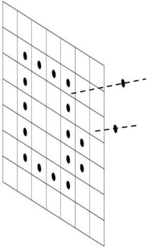
Outlier depth points detected within the filter that showed extreme depth changes, so the filter eliminates extreme depths to create a sharp object surface.
Flow CPD refines the relative pose of the rigid object by fusing depth and optical flow. We compared our results with ICP and Vicon, which provide the gold standard for pose estimation by tracking a non-symmetric plate attached to the tracked object. Then the poses of the object can be tracked in samples. Vicon can provide ground truth pose estimates. The model point cloud data (Pm) and the target point cloud data (Pt) can be transformed using pose estimates (R and T), see (1). The CPD algorithm is an efficient algorithm to align two-point cloud sets. The CPD algorithm considers pose estimation as a probability density estimation problem. The points in the 3D world are defined by the 3-dimensional coordinate system (X,Y,Z), the color imagery correspondences (x, y) are defined in (2), and the optical flow function is defined by f. The flow vectors can be defined as xf,yf, see (3). One set is defined as GMM centroid and the other point set is defined as data points. The CPD algorithm calculates the spatial transformation between two-point clouds by maximizing the GMM likelihood function. It can calculate the pose of the objects by modeling the objects as rigid or non-rigid objects. The best matches between the model and the target imagery are found by calculating Pmt, where s defines the scale, and w defines the weighs of noise and outliers, see (4). Here, we rejected outliers and fused the optical flow with depth, which leads to improved pose recovery and is referred to as Flow-CPD. The accuracy of our algorithm can be compared with the ground truth pose. However, we need to calibrate Kinect II and Vicon, which is explained next.
We have compared the pose estimates with the Vicon. Since the ground truth pose is captured by the gold standard tracker (Vicon), the pose estimated by the Kinect was calibrated with the Vicon. The pose changes are the same at all locations, but the pose is transferred differently in the 3-axis. Multiple pose estimates can be used to find a calibration matrix.
In the case of a rigid object rotation observed with respect to 2 cameras with different orientations, the poses of the cameras can be identified as R1 and R2. Then the relationship between the poses can be formulated, see (5).
We can simplify the above equation. Therefore, we noted the Rx calibration matrix which transforms the pose from R1 to R2. Then we create (5) by tracing the coordinate system in Fig. 2, and we can define (6) and (7). The transformation between the base of the plate and Kinect’s reference coordinates can be simplified, see (8). Multiplications of the poses by the transpose of the same amount of rotation equals to identity matrix I, see (9), and can be redefined with the relative pose (10).
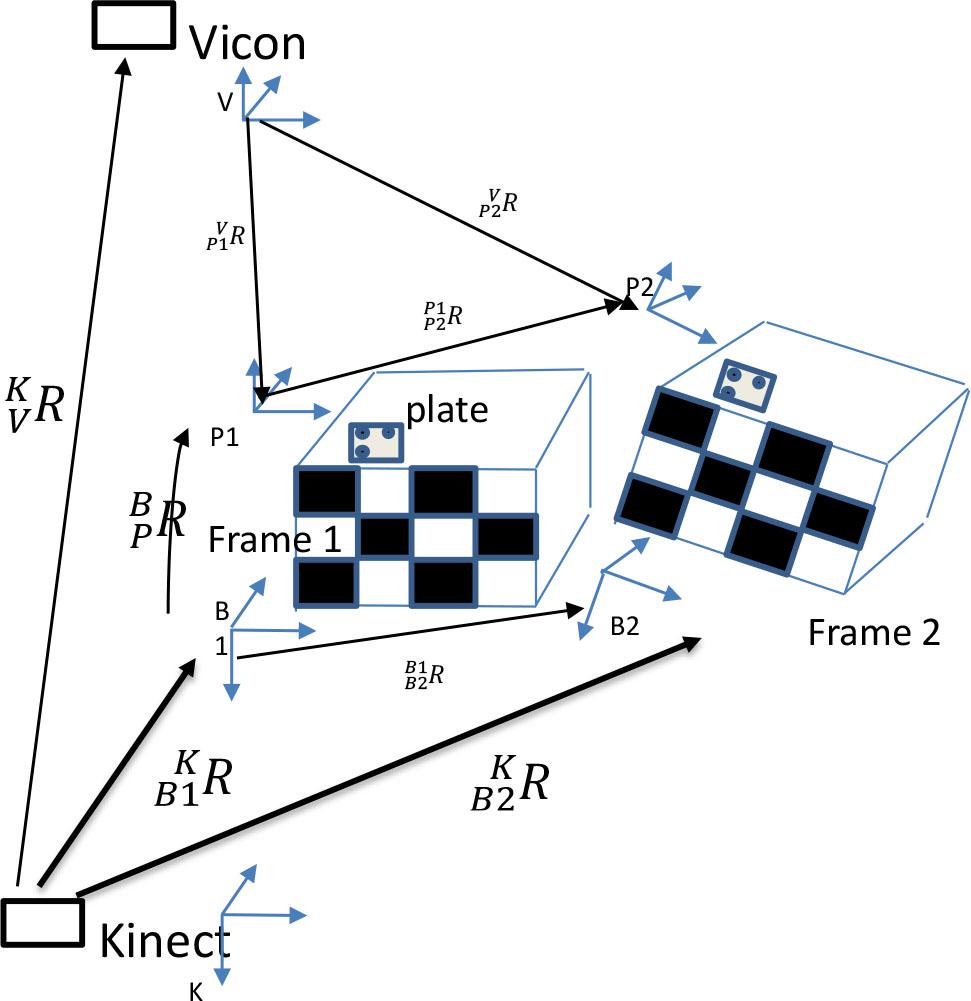
The calibration framework and the transformations between the coordinate systems have been specified.
The same physical rotation Rθ can be quantified from two different cameras. We can decompose the rotation into U1, U2, see (11) and (12).
If you write Rθ with two derivations, which are defined in different matrices, see (13) and (14).
Then the calibration matrix (
We can find
The calibration matrices (
Angular rotations can be formulated as follows, see (19), (20), and (21).
The calibration matrix Rx transforms the same amount of rotation from R1 to R2 with 2π mod. Camera poses can be transformed using Rx, see (21). In this way, the relative poses of two differently oriented cameras can be directly compared using the calibration matrices
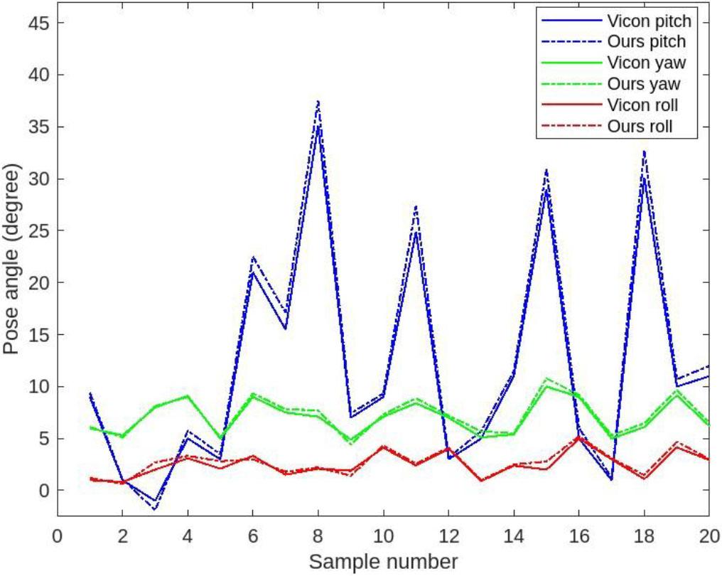
After calibration, Vicon and the pose estimates show close alignment.
We tested the proposed algorithm to evaluate R and T. Laboratory tests using a Vicon motion capture device and a public pose dataset were also used to evaluated the algorithms. The results of the Flow-CPD algorithm were also compared with the Vicon. Flow-CPD provided a good alignment with the pose estimated by Vicon. Model and target objects are shown in Fig. 4. CPD finds the pose from model to target, see pose matches in Fig. 5. Pose matches are given for Flow-CPD, see Fig. 6. Model point clouds are transformed to target point cloud data using the estimated pose parameters. We have tested the pose estimation methods in a series of experiments and published the results.
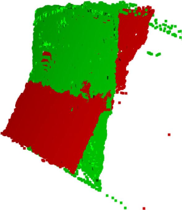
Rigid object was rotated by 15 degrees, model and target point clouds are given.
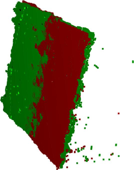
Pose is calculated using the CPD algorithm and the point clouds were aligned based on estimates leading to errors.
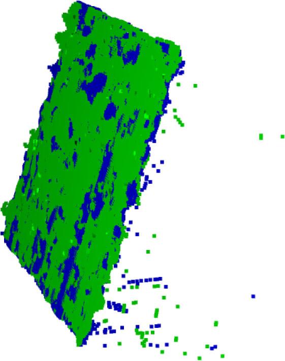
Pose is calculated using Flow-CPD and the point clouds were aligned based on the estimates of Flow-CPD. It can be seen that the model and target point clouds interact with each other, showing improved accuracy.
We first tested the Flow-CPD algorithm to evaluate rotational angles and translations. The results have shown that the Flow-CPD algorithm computes the pose of the rigid object with higher accuracy than CPD and shows close alignment with the ground truth. Instead of using depth only measurements, Flow-CPD fuses depth and optical flow, resulting in improved pose matches when tested with the Vicon. Pose errors are compared and the CPD algorithm has a 3.32 degree mean square error (MSE), but Flow-CPD shows improved pose recovery and an MSE of 0.76 degrees. Flow-CPD provides low-cost and high-accuracy pose estimates by upgrading Microsoft Kinect II.
In this study, the proposed method demonstrates improved accuracy in relative pose estimation. The Flow-CPD algorithm is shown to be a reliable, high-precision tracking approach for indoor environments that overcomes the inherent limitations of the Kinect II sensor. In addition, a calibration framework is introduced that enables external calibration across multiple viewpoints. The Flow-CPD approach also shows potential for adaptation to multi-robot pose estimation and cooperative tasks in large-scale production lines, which will be further investigated in future work.