
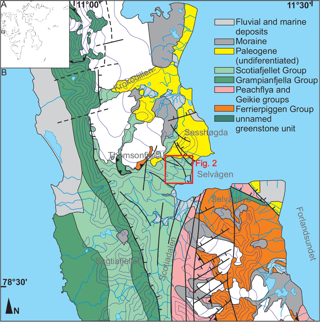
Figure 1.
(A) Simplified map of Svalbard. Outlined box shows the location of Figure 1b; (B) Geological map of central Prins Karls Foreland (after Dallmann, 2015). Fig. 2a marked with red rectangle.
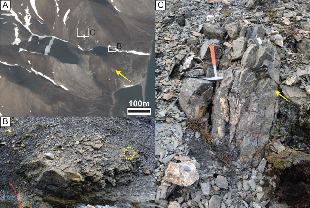
Figure 2.
(A) Satellite image of the sampling area. Example of carbonate vein rich in siderite marked with yellow arrow. (toposvalbard.no) (B) Outcrop of magnesite in contact with surrounding black marbles and phyllites marked with red dotted line. (C) Close up image of the magnesite outcrop with visible bands of black metachert (marked by arrow). Note multiple dolomite veins crosscutting the vertical foliation within magnesite.
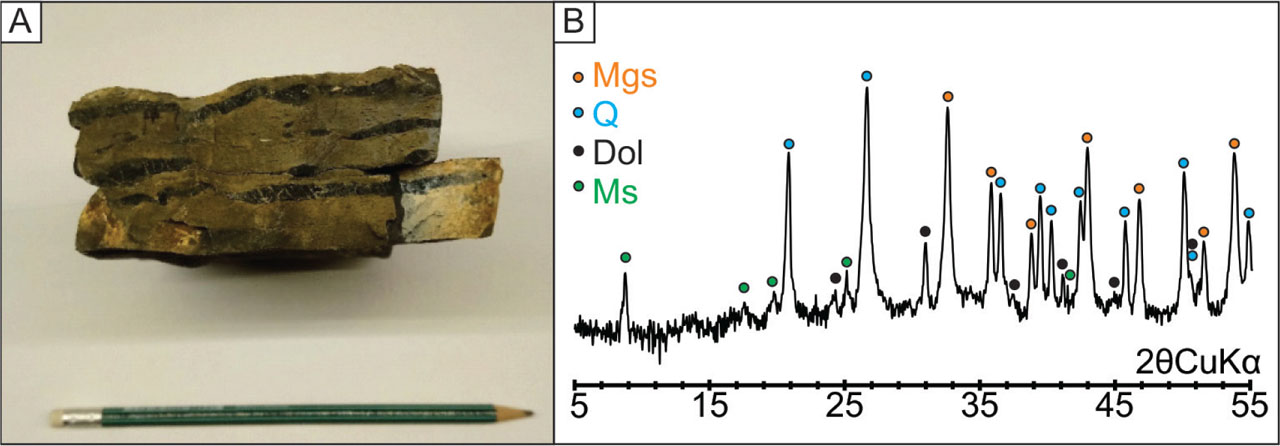
Figure 3.
(A) Photograph of a sample of the metacarbonate with cherts. Cherts are preserved as horizontal black discontinuous bands and smaller nodules within microcrystalline metacarbonate matrix (B) Mineral composition of the metacarbonate rock based on the XRD pattern.
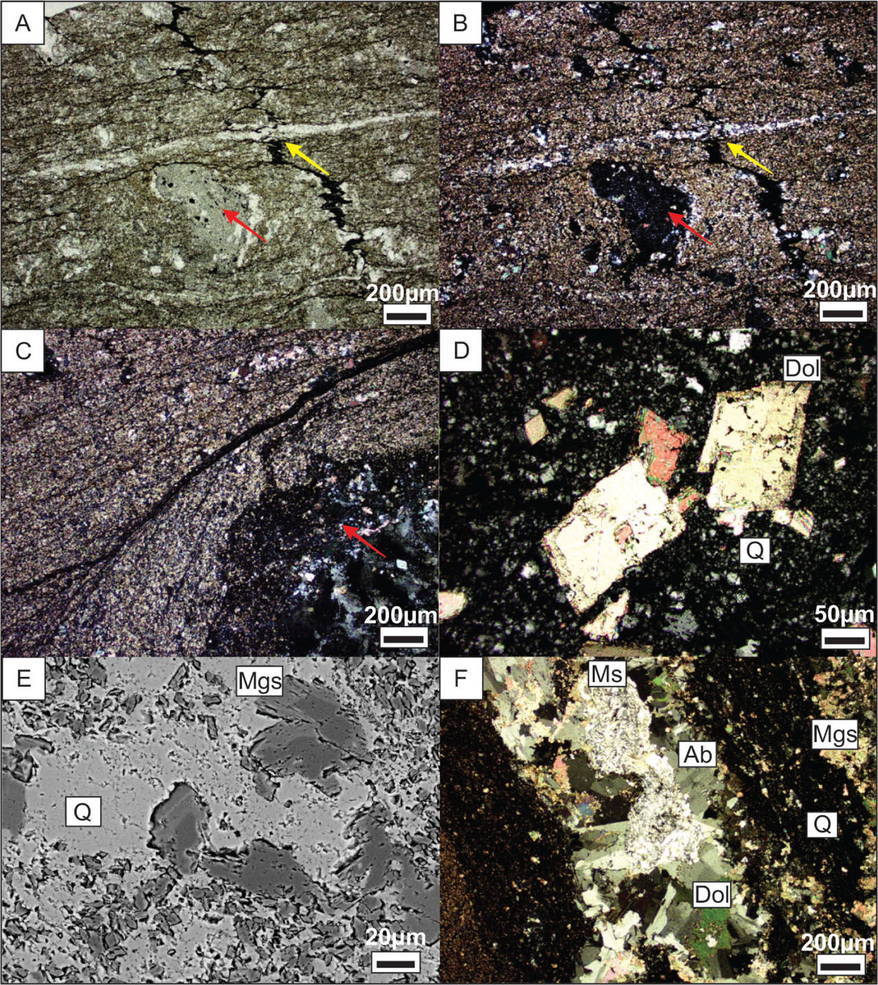
Figure 4.
(A, B) Microphotographs of laminated magnesite rock around a small chert nodule in the centre (red arrow). A stylolite (yellow arrow) oblique to foliation and crosscut by a dolomitic vein is apparent (optical microscopy, A—1N, B—NX). (C) Foliation deflected around chert nodule marked with red arrow (D). Euhedral dolomite crystals embedded in finely crystalline silica of the chert (optical microscopy, NX). (E) Subhedral, zoned magnesites embedded in chert quartz matrix (SEM/BSE image). (F) First generation of dolomitic veins with albite and muscovite present.
Table 1.
Representative elemental composition of magnesite rim and core (semi-quantitative SEM/EDS analysis normalized to 100%).
| COMPONENT | CORE | RIM | ||
|---|---|---|---|---|
| wt% | mol% | wt% | mol% | |
| CO2 | 52 | 51 | 52 | 51 |
| MgO | 47 | 49 | 44 | 48 |
| Fe2O3 | 1 | 0.2 | 4 | 1 |
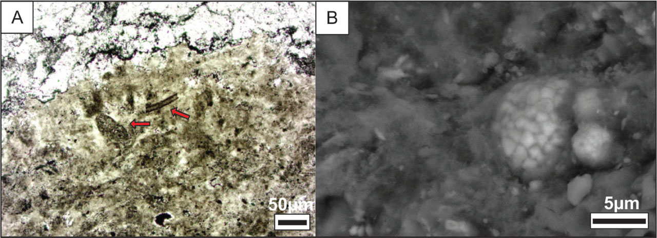
Figure 5.
(A) Aggregates of detritus with biogenic structures (red arrows) (optical microscopy, 1N). (B) Framboidal pyrite embedded in chert. (SEM/BSE image).
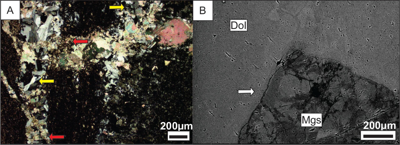
Figure 6.
(A) Second generation dolomite veins (red arrows) crosscutting the first generation albite veins (yellow arrows; optical microscopy, NX). (B) BSE image of the reaction rim around the magnesite grain manifested by elevated Fe content in dolomite (white arrow).
Table 2.
Carbonaceous matter Raman bands positions after decomposition (FWHM).
| BAND | CENTRE | INTENSITY | FWHM |
|---|---|---|---|
| D4 | 1244.6 | 18 | 381 |
| D1 | 1349.4 | 142 | 80 |
| D3 | 1531.2 | 19 | 144 |
| G | 1593.0 | 73 | 44 |
| D2 | 1615.2 | 63 | 33 |
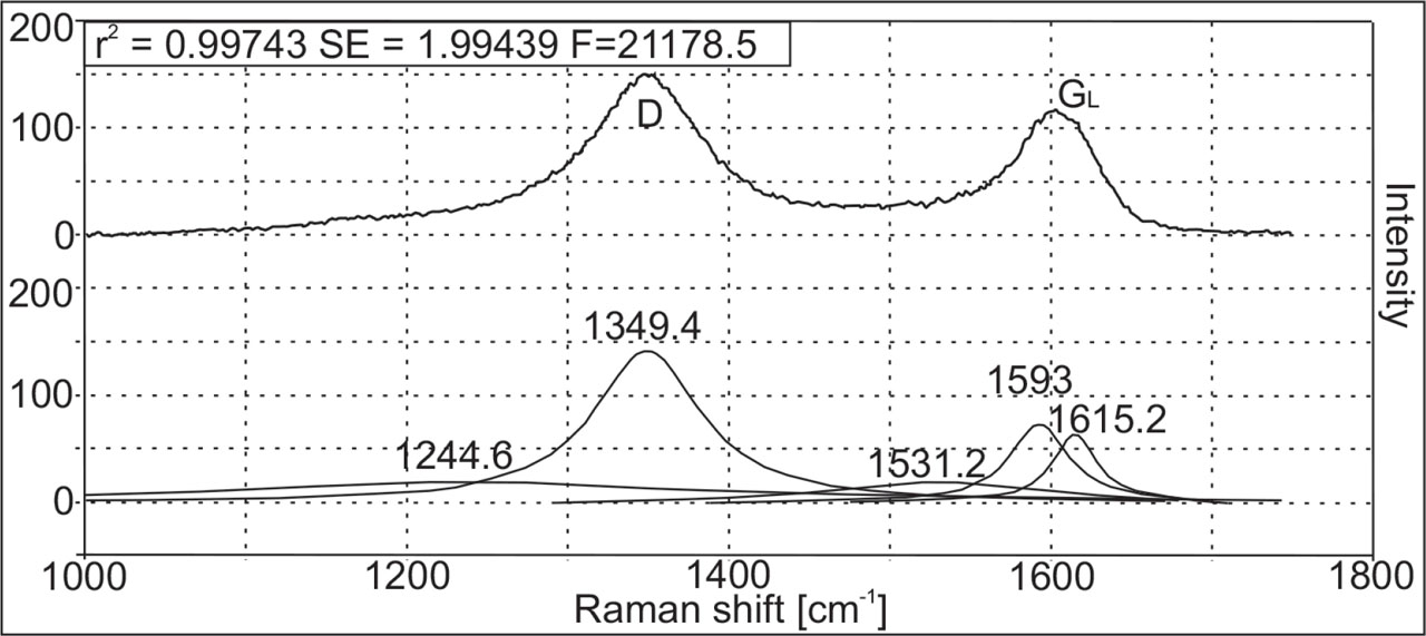
Figure 7.
Raman spectrum of carbonaceous matter (top) and its deconvolution (bottom); R2—coefficient of determination, SE, F—area. SE, standard error.