
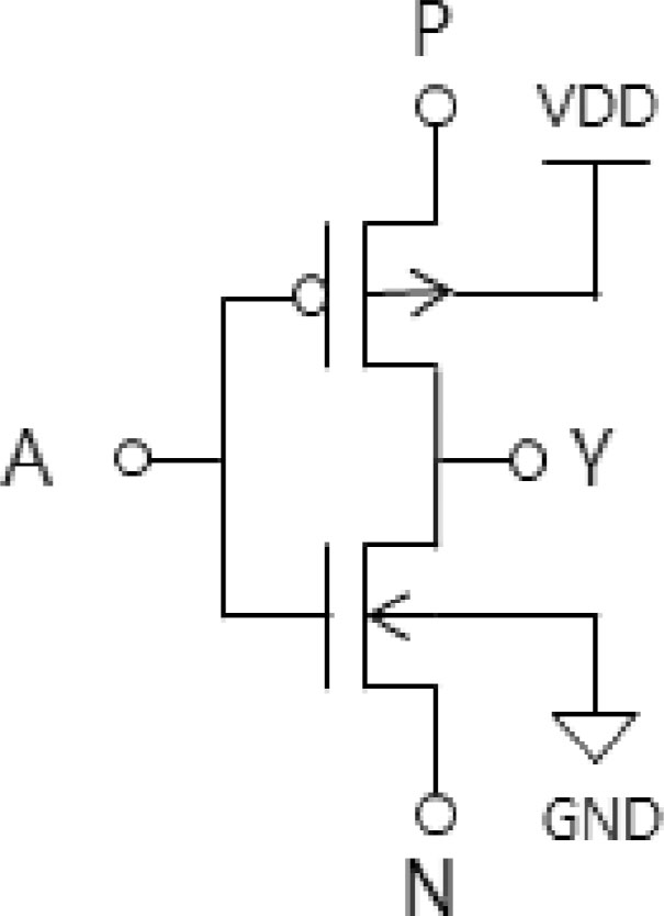
Figure 1:
Basic GDI cell and its function. GDI, gate diffusion input.
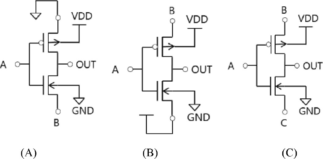
Figure 2:
Functional block diagram of fingerprint sensor chip. (A) AND (B) OR (C) MUX.
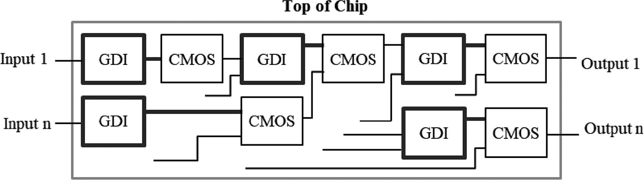
Figure 3:
Hybrid GDI technique. GDI, gate diffusion input.
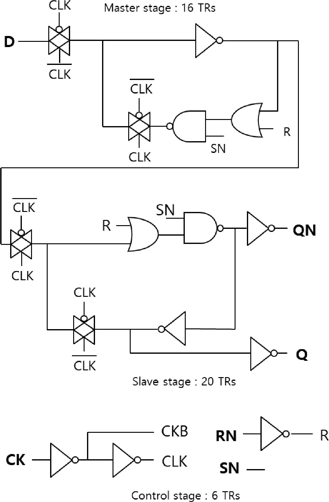
Figure 4:
Conventional CMOS set/reset D flip-flop (DFFSR_C).
Table 2:
Truth table of DFFSR operation.
| RN | SN | D | CK | Q[n+1] | QN[n+1] |
|---|---|---|---|---|---|
| 0 | 0 | X | X | 0 | 1 |
| 1 | 0 | X | X | 1 | 0 |
| 0 | 0 | X | X | 1 | 0 |
| 1 | 1 | 0 | ↑ | 0 | 1 |
| 1 | 1 | 1 | ↑ | 1 | 0 |
| 1 | 1 | X | ↓ | Q[n] | QN[n] |
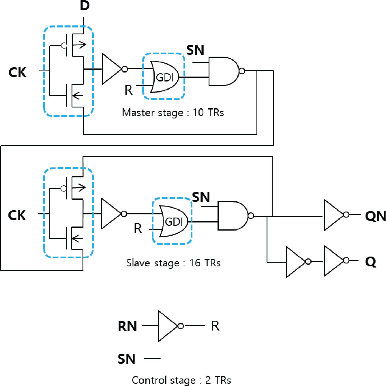
Figure 5:
Proposed GDI set/reset D flip-flop (DFFSR_G). CK, DFFSR_G, GDI, gate diffusion input.
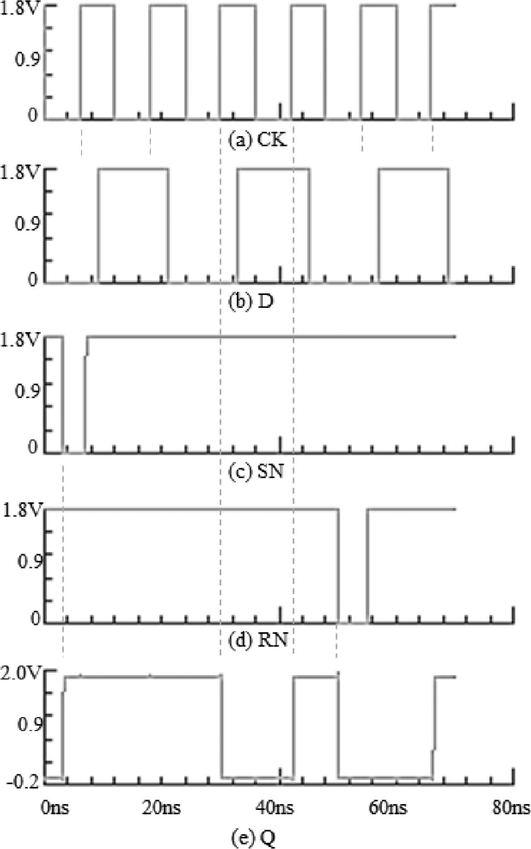
Figure 6:
Functional simulation result of DFFSR_G.
Table 3:
Summary of DFFSR performance comparison.
| Number of MOS TR. | clk_q_tplh (sec) | clk_q_tphl (sec) | average (sec) | power_avg (uW/MHz) | |
|---|---|---|---|---|---|
| DFFSR_C | 42 | 3.60E-10 | 3.17E-10 | 3.39E-10 | 0.211 |
| DFFSR_G | 28 | 5.97E-10 | 6.04E-10 | 6.00E-10 | 0.205 |
| Improvement | 33% | –77% | 3% |
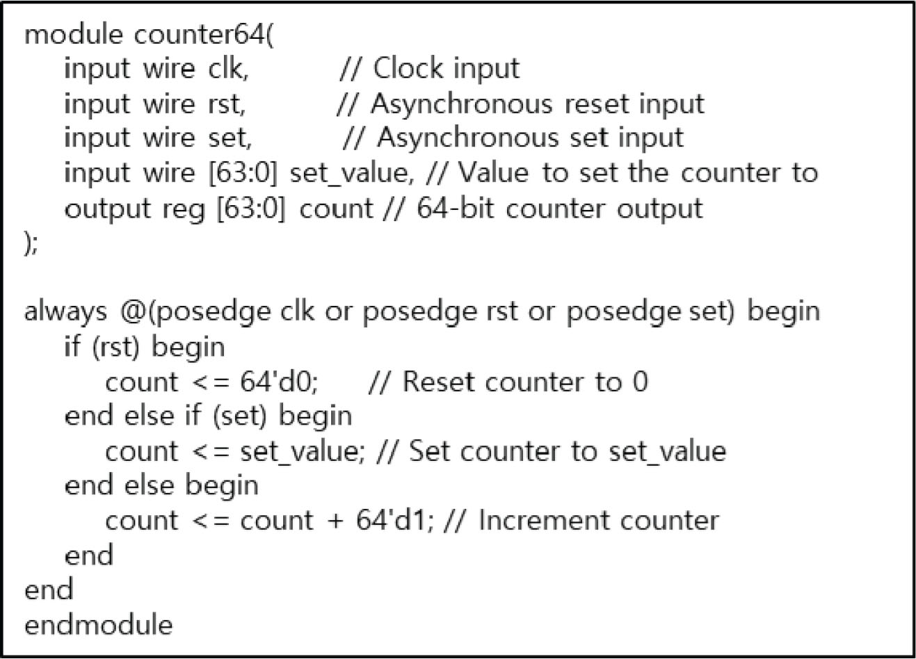
Figure 7:
Verilog-HDL based RTL code for synthesis and P&R verification using DFFSR_G. P&R, placement and routing.
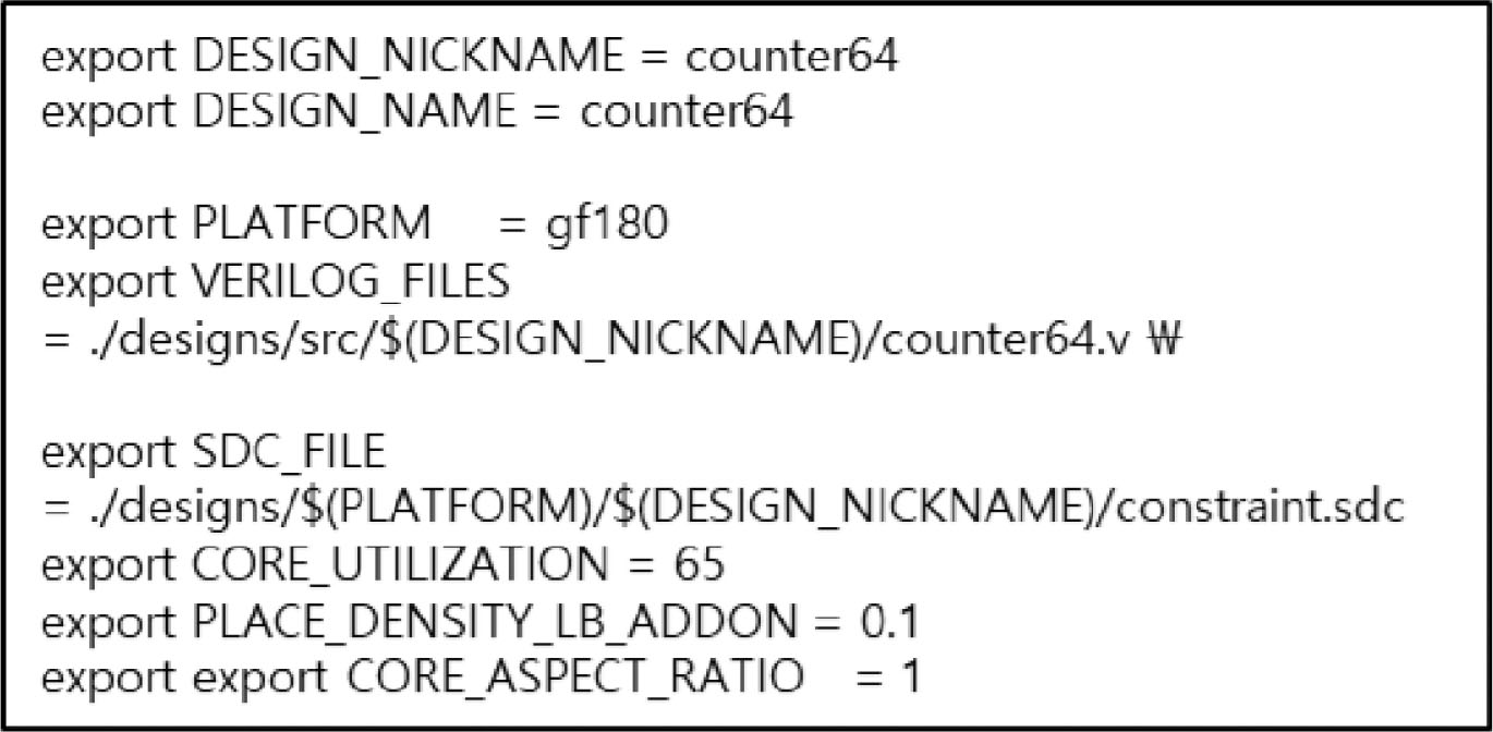
Figure 8:
Configuration condition for openROAD.
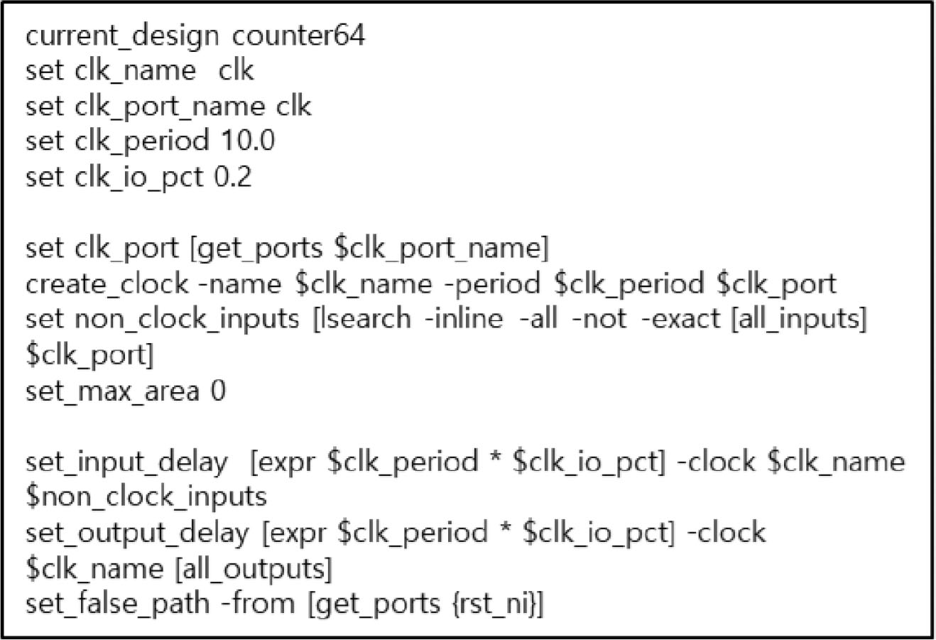
Figure 9:
SDC condition for openROAD.
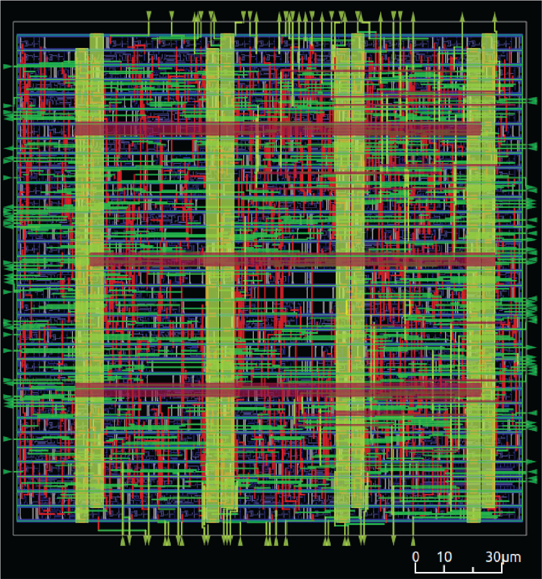
Figure 10:
Layout result of 64 bit counter using DFFSR_G.