
1. INTRODUCTION
In modern aviation, maintenance is not only a scheduled technical activity but also a reliability engineering process that prevents component degradation from developing into unsafe system-level failures. Aircraft components operate under combined mechanical, thermal, vibrational, and environmental loading, especially in areas close to the engine. These conditions can promote progressive structural damage in metallic components. Fatigue is one of the most critical degradation mechanisms because repeated cyclic loading can initiate microcracks that gradually propagate during service. Recent aerospace fatigue studies show that cyclic loading, vibration, thermal exposure, and material defects may jointly influence crack initiation and fatigue life in safety-critical components (He et al., 2023; Nikitin et al., 2023; Naveen et al., 2025; Hui et al., 2025).
The engine fire protection system is safety-critical because it must suppress fire in one of the most hazardous zones of aircraft operation. Its reliability depends not only on the fire extinguisher bottle but also on the integrity of the agent distribution path, including piping assemblies, fittings, outlet components, and discharge points. Damage to any part of this path may reduce discharge pressure, limit extinguishing-agent delivery, and compromise fire-suppression effectiveness during an emergency. Previous studies on aircraft piping and safety-system degradation have reported several relevant failure mechanisms, including corrosion, seal degradation, joint cracking, welded-joint fatigue, transient pressure effects, and leakage from degraded connections (Čerňan et al., 2019; Sha et al., 2024). These mechanisms indicate that a local defect in a small component can create a broader reliability concern when the component is part of a safety-critical distribution system.
This study was motivated by a crack found on the outlet discharge component of the engine fire extinguisher system during C-Check maintenance of an Airbus A330-900 aircraft. According to the Illustrated Parts Catalog, the outlet discharge is part of the engine fire-extinguishing distribution path, connecting the extinguisher bottle discharge line to the engine nacelle discharge area. Therefore, cracking at this location is critical because it may cause leakage in the final delivery path of the extinguishing agent. Although the observed defect was small, its position within the fire-extinguishing system makes it important for reliability and airworthiness assessment.
From an engineering perspective, cracking in the outlet discharge is consistent with a progressive failure process influenced by operational loading. Components installed in the engine nacelle are exposed to repeated vibration, temperature fluctuations, and thermal expansion–contraction cycles. These conditions are compatible with high-cycle fatigue, in which low-amplitude and high-frequency loading may initiate and propagate cracks over time. The S–N or stress-life approach provides a basis for interpreting the relationship between cyclic stress amplitude and fatigue life, while Basquin-type relations are commonly used to approximate high-cycle fatigue behavior in metallic structures (Fang et al., 2017; Khashaba & Alssayegh, 2025). Crack propagation can also be interpreted using linear elastic fracture mechanics and Paris Law, which relates crack growth rate to the stress intensity factor range under cyclic loading (Muhammad et al., 2021; Uygur, 2024; Bai et al., 2025).
Vibration-induced stress and thermal stress are particularly relevant to the present case. Engine-area components may experience continuous excitation, and resonance may amplify local cyclic stress when the excitation frequency approaches a structural natural frequency. Thermal cycling can further increase stress concentration because repeated heating and cooling cause material expansion and contraction, especially near joints, geometric transitions, or constrained interfaces. Studies on thermo-vibration coupling and aerospace material fatigue show that vibration, resonance, thermal expansion, and stress concentration may act together to accelerate crack initiation and propagation (Muhammad et al., 2021; He et al., 2023; Liu et al., 2024; Hui et al., 2025). Therefore, the outlet-discharge crack should be assessed as a possible combined mechanical–thermal fatigue problem rather than an isolated surface defect.
The reliability consequence of this defect requires a system-level assessment in addition to a material-level explanation. Because the outlet discharge forms part of the fire-extinguishing agent delivery path, a crack may cause leakage and reduce system effectiveness. Failure Mode and Effects Analysis (FMEA) provides a structured method for evaluating failure modes, causes, effects, and maintenance priorities. In aerospace maintenance, FMEA is often combined with fatigue analysis, damage-tolerance concepts, safe-life assessment, and inspection-based decision-making, particularly when complete experimental data are unavailable (Lv et al., 2020; Nikishkov et al., 2021; Moroney & Verma, 2023; Delpuech et al., 2024). This combined approach is suitable for real maintenance cases where the available evidence consists of inspection findings, operational context, and engineering assumptions rather than laboratory validation.
Fatigue crack growth has been studied extensively in aircraft structures, turbine components, landing gear, welded assemblies, and metallic joints. However, studies specifically addressing aircraft engine fire extinguisher outlet discharge components remain limited. Most fatigue studies focus on primary structures or propulsion components, while fire-extinguisher distribution components receive less attention. In addition, many fatigue investigations are conducted in laboratory or simulation environments and may not fully represent actual maintenance conditions. This creates a research gap for case studies that integrate inspection evidence, fatigue interpretation, crack-growth assessment, safety-margin evaluation, and FMEA for safety-critical aircraft fire protection systems.
This study analyzes the likely failure mechanism of a crack found in the outlet discharge component of an Airbus A330-900 engine fire extinguisher system during C-Check maintenance. The working assumption is that the observed crack is most likely the result of fatigue-induced propagation under cyclic loading, with vibration-induced and thermal stresses acting as accelerating factors. Specifically, this study evaluates whether these mechanisms can explain the observed defect, assesses the potential reliability and airworthiness implications of cracking in the discharge path, and examines the role of corrective maintenance in restoring system functionality. The study is limited to a qualitative and semi-quantitative engineering assessment based on inspection data, operational context, and representative fatigue assumptions. Nevertheless, it provides a practical framework for supporting reliability-based maintenance decisions when detailed experimental testing, advanced non-destructive inspection, material characterization, and finite element analysis are unavailable.
2. METHODOLOGY
This study used a case-study approach combined with applied engineering analysis to evaluate a crack detected during C-Check maintenance on the outlet discharge component of the engine fire extinguisher system of an Airbus A330-900. This approach was selected because the defect occurred in an actual maintenance environment and was therefore interpreted from operational evidence rather than controlled laboratory testing. Aerospace failure-case analysis is commonly used to infer crack initiation and propagation mechanisms when destructive testing, detailed material characterization, or full experimental replication is unavailable (Lv et al., 2020; Zhang et al., 2023).
The analysis was qualitative and semi-quantitative. The qualitative assessment interpreted the visual crack evidence, component function, operating environment, failure consequences, and plausible loading mechanisms. The semi-quantitative assessment estimated fatigue behavior, crack-growth tendency, structural margin, and system-level risk. This combined approach was necessary because the available evidence consisted of maintenance records, visual observations, and operational context, without experimental fatigue testing, non-destructive testing, finite element modeling, or detailed material characterization. In similarly constrained cases, durability-damage-tolerance analysis, safe-life concepts, service-data-based assessment, structural health monitoring inference, and advanced fracture modeling can support maintenance prioritization without new specimens or full-scale destructive tests (Shekhter et al., 2015; Qiu et al., 2016; Demiral & Duran, 2023; Moroney & Verma, 2023).
2.1. Research Object and Maintenance Context
The research object was the outlet discharge component, which forms part of the extinguishing-agent distribution path from the fire extinguisher bottle to the engine nacelle region. The crack was detected during C-Check maintenance, which provided the real inspection context for the case analysis. The defect was located in the engine nacelle area, Zone 420, where components are exposed to combined thermal and mechanical loading, including vibration, temperature fluctuation, and repeated operational stress. The observed crack length was estimated to be less than 5 mm, indicating an early-stage visible defect. Earlier screening estimated the exposure at 6,000–10,000 cycles; however, the verified C03 maintenance record showed 5,642 flight cycles and 10,834 flight hours. These verified values were used for comparison with the fatigue crack-growth assessment.
2.2. Data Collection
Data were obtained from aircraft maintenance documentation and direct inspection during maintenance. The primary data sources were inspection records, visual observations, and operational context. Inspection was performed during the functional check of the engine fire extinguisher system and focused on the distribution piping and outlet discharge components. The inspection followed the Aircraft Maintenance Manual and C-Check task cards.
The main finding was a surface crack on the outlet discharge component. Because the crack was identified visually, it was treated as an observable surface defect rather than a fully characterized crack geometry. The operational context was then used to assess whether the defect was consistent with fatigue, vibration-induced stress, and thermal stress in the engine nacelle environment.
2.3. Failure Analysis Procedure
The failure analysis focused on three possible mechanisms: fatigue, vibration-induced stress, and thermal stress. Fatigue was considered because the defect appeared after repeated service exposure. Vibration-induced stress was evaluated because the component is located in an engine nacelle environment, where continuous excitation can contribute to high-cycle fatigue. Thermal stress was considered because repeated heating and cooling may create expansion–contraction cycles that accelerate crack initiation, especially near joints, geometric transitions, or constrained interfaces.
The analytical process began with visual interpretation of the defect and assessment of the component function. A simplified Basquin-type relation was then used to qualitatively interpret fatigue life. S–N curve data and Basquin-type models are commonly applied to describe the relationship between stress amplitude and cycles to failure in aircraft-related high-cycle fatigue assessment (Fang et al., 2017). In this study, the Basquin-type relationship was used as a qualitative consistency check to assess whether the observed crack could be associated with high-cycle fatigue under the estimated operational loading; it was not used to calculate a certified fatigue life or remaining life. More advanced fatigue-life prediction methods, including data-driven and machine-learning approaches, may improve prediction accuracy when sufficient training data and validated material information are available (Gbagba et al., 2023). Because the material specification and heat-treatment conditions for Outlet Discharge P/N 52002066-1 were unavailable, representative high-strength aerospace aluminum fatigue properties were used only for plausibility assessment, not for certified life prediction.
2.4. Crack Growth Modeling
Crack-growth behavior was evaluated using a Paris Law-based crack propagation approach. Paris Law is expressed as Eq. (1):
where da/dN is the crack growth rate per cycle, C and m are material-dependent constants, and ΔK is the stress intensity factor range. In this study, ΔK was estimated from cyclic stress, crack length, and a geometry correction factor using Eq. (2): where Y is the geometric correction factor, Δσ is the cyclic stress range, and a is the crack length. Paris-type formulations are widely used in fatigue crack-growth and damage-tolerance studies, although the Paris Law constants, stress amplitude, and geometric correction factor depend strongly on alloy, geometry, residual stress, and loading conditions (Muhammad et al., 2021; Fang et al., 2017; Čerňan et al., 2019; He et al., 2023; Uygur, 2024; Bai et al., 2025).The Paris Law constants were adopted as representative calibrated values for high-strength aerospace aluminum alloys. ASTM International (2022) was used as the reference for fatigue crack-growth testing, while Tada et al. (2000) and Anderson (2017) justified the fracture-mechanics formulation and the Y = 1.12 edge-crack correction.
These values were implemented in MATLAB to calculate incremental crack growth under cyclic loading. The procedure defined the initial crack length, number of cycles, stress amplitude, geometry correction factor, and Paris Law constants. Then, ΔK and da/dN were recalculated iteratively as crack length increased. Crack length and crack-growth rate were recorded at selected cycle intervals to generate the crack-growth curve. This simulation was used as a semi-quantitative interpretation tool and did not replace finite element analysis, fracture testing, or validated component-specific crack-growth assessment.
2.5. Safety Factor Evaluation
Structural margin was evaluated using a simplified safety factor based on the ratio between allowable stress and estimated operational stress. The safety factor was calculated as Eq. (3):
where SF is the safety factor, σallow is the allowable stress, and σworking is the estimated operational stress. In this study, the safety factor was used as a semi-quantitative indicator of structural margin rather than as a certification-level design value. Aerospace literature emphasizes that no universal safety-factor threshold applies to all components, as interpretation depends on safe-life concepts, reliability targets, operational context, defect condition, and damage-tolerance assessment (Shekhter et al., 2015; Moroney & Verma, 2023; Delpuech et al., 2024; Khashaba & Alssayegh, 2025). Therefore, the calculated margin was interpreted in light of the presence of cracks, component criticality, and the potential consequences of leakage in the fire-extinguishing distribution path.2.6. FMEA-Based Risk Assessment
Failure Mode and Effects Analysis (FMEA) was applied to evaluate the risk of cracking within the engine fire extinguisher system. The procedure identified potential failure modes, likely causes, system effects, and mitigation actions. The Risk Priority Number (RPN) was calculated as expressed in Eq. (4) (the formula used for risk quantification):
where S is severity, O is occurrence, and D is detection. Severity represented the effect of failure on safety and system performance. Occurrence represented the likelihood of failure under the observed operating conditions. Detection represented the likelihood of identifying the failure before it produced an adverse effect. Higher RPN values indicated higher maintenance priority.Although universal FMEA thresholds for aerospace fire-protection systems are not consistently documented, maintenance risk prioritization is commonly supported by failure-case analysis, safe-life assessment, reliability analysis, and damage-tolerance frameworks (Lv et al., 2020; Nikishkov et al., 2021; Moroney & Verma, 2023; Delpuech et al., 2024; Khashaba & Alssayegh, 2025). In this study, the FMEA compared three failure modes: outlet discharge cracking, distribution piping blockage, and extinguisher bottle pressure loss. This comparison was used to determine the relative maintenance priority of the observed crack.
2.7. Corrective Maintenance Verification
Corrective maintenance was evaluated based on the action taken after the defect was identified. The cracked outlet discharge component was replaced with a serviceable unit through the robbing method. After replacement, an operational test was performed to verify system serviceability, absence of observable leakage, and normal flow characteristics. Replacement was selected because a structural crack in a safety-critical fire-extinguishing distribution component may compromise system reliability. Maintenance and damage-tolerance frameworks generally support repair, refurbishment, or replacement when a detected damage state cannot be justified for continued operation within acceptable reliability and airworthiness margins (Shekhter et al., 2015; Moroney & Verma, 2023; Khashaba & Alssayegh, 2025).
2.8. Methodological Limitations
This methodology provides a practical engineering interpretation rather than an exact fatigue-life certification. The crack was visually detected and was not supported by dye penetrant testing, ultrasonic testing, fractography, or microscopic material characterization. No experimental fatigue testing was performed on the outlet discharge material. The Paris Law constants, stress amplitude, and geometric correction factor were assumed values rather than component-specific, validated data. Finite element analysis was not conducted; therefore, local stress concentration and crack-tip stress intensity were not modeled in high fidelity. Long-term reliability data for similar components were also unavailable. Accordingly, fatigue was assessed as the most plausible mechanism, while material susceptibility, manufacturing effects, and environmental cracking could not be excluded.
2.9. Analysis Flow
The analysis followed a structured sequence. First, the crack was identified and documented during C-Check maintenance. Second, the component function and system consequence were evaluated. Third, the operating environment was assessed to identify fatigue, vibration-induced stress, and thermal stress as plausible mechanisms. Fourth, fatigue behavior was interpreted using a simplified Basquin-type model. Fifth, crack growth was evaluated using the Paris Law simulation. Sixth, the structural margin was assessed using safety factor analysis. Seventh, system-level risk was evaluated using FMEA. Finally, corrective maintenance and operational testing were assessed to confirm restoration of system function. The complete methodological workflow is illustrated in Figure 1.
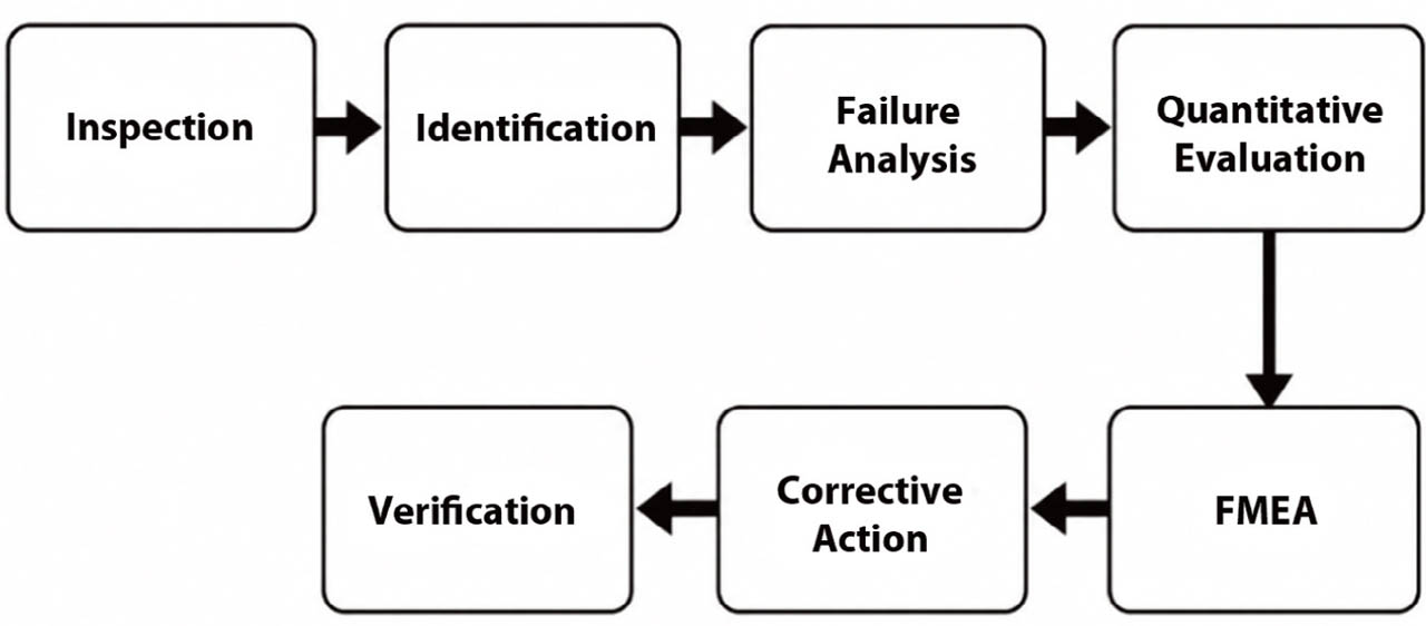
Fig. 1.
Structured analysis workflow illustrating the sequential process of system evaluation.
The main case information, analytical assumptions, and simulation parameters used in this study are summarized in Table 1.
Table 1.
Methodological parameters and assumptions.
| Parameter | Extracted Value / Description | Methodological Role |
|---|---|---|
| Aircraft type, Maintenance event | Airbus A330-900, C-Check C03 | Case object, Inspection context |
| Component analyzed | Outlet discharge Engine fire extinguisher system | Defective component, Safety-critical aircraft system |
| Inspection focus | Distribution piping and outlet discharge | Data collection scope |
| Crack length | < 5 mm | Main observed defect size |
| Defect location | Engine nacelle, Zone 420 | Operational environment |
| Operational exposure | 5,642 FC and 10,834 FH | Fatigue evaluation reference |
| Data sources | Inspection records, visual observations, AMM & task cards | Primary evidence-based, Maintenance procedure reference |
| Analysis type | Qualitative and semi-quantitative engineering analysis | Analytical approach |
| Fatigue method | Simplified Basquin-type relation | Fatigue life estimation |
| Crack growth method | Paris Law-based simulation | Crack propagation estimation |
| Representative stress amplitude | 95 MPa | Localized cyclic loading assumption |
| Paris Law constants | C =2.5 × 10⁻¹¹, m = 3.2, Y = 1.12 | Crack growth simulation parameter |
| Safety evaluation | Safety factor analysis | Structural margin assessment |
| Risk evaluation | FMEA | System-level risk assessment |
| RPN equation basis | Severity × Occurrence × Detection | Failure prioritization metric |
3. RESULTS
3.1. Crack Observation and Operational Context
Inspection during C-Check maintenance identified a visible surface crack on the outlet discharge component of the Airbus A330-900 engine fire extinguisher system, as shown in Figure 2. The component was located in the engine nacelle area, specifically Zone 420 in the E area, where aircraft system components are exposed to repeated mechanical vibration, temperature fluctuations, and operational loading. The estimated crack length was less than 5 mm, indicating an early-stage visible structural defect. Although relatively small, the crack was significant because its location in the fire-extinguishing-agent distribution path means that leakage could reduce discharge pressure and impair delivery of the extinguishing agent to the engine nacelle.
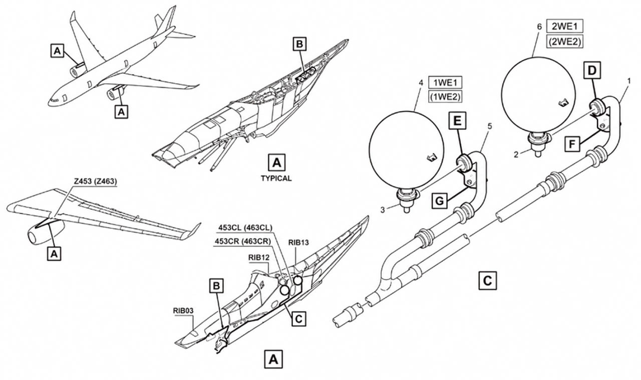
Fig. 2.
Airbus A330-900 engine fire extinguisher system and outlet discharge location in the engine nacelle area, showing the installation zone and observed crack location.
The crack location on the outlet discharge is shown in Figure 3. Based on visual inspection, the crack appeared consistent with a stress-influenced defect rather than an isolated random surface mark. However, because no fractography, dye penetrant testing, ultrasonic testing, or microscopic material characterization was performed, this observation should be interpreted as indicative rather than conclusive. Previous studies have shown that fatigue cracks in aerospace materials may follow local stress fields, microstructural anisotropy, or residual-stress paths under vibration and cyclic loading (Muhammad et al., 2021; He et al., 2023; Hui et al., 2025).
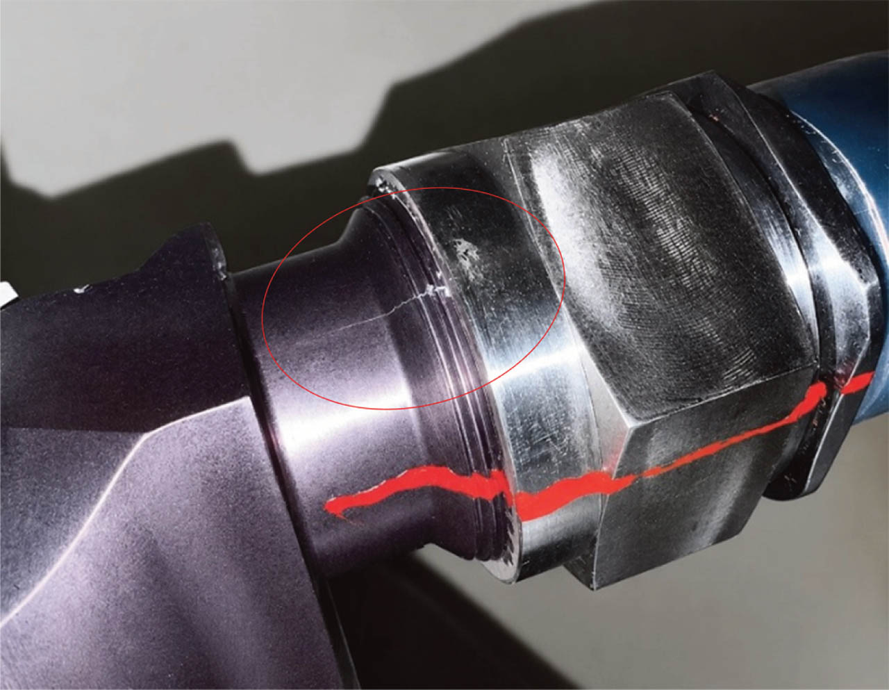
Fig. 3.
Close-up visual observation of the crack on the outlet discharge component.
The crack was detected after the aircraft had accumulated 5,642 flight cycles and 10,834 flight hours. This exposure range was considered consistent with early fatigue damage under repeated service loading. Accumulated cycles are commonly used in maintenance and damage-tolerance assessments because crack initiation often develops at stress risers, local defects, or microstructural features under cyclic loading (Lv et al., 2020; Nikishkov et al., 2021; Moroney & Verma, 2023; Delpuech et al., 2024; Khashaba & Alssayegh, 2025). Therefore, the observed crack was treated as physically consistent with high-cycle fatigue in a component exposed to engine vibration and thermal cycling.
3.2. Fatigue Life Estimation using an S–N Approach
Fatigue life was interpreted using the simplified Basquin-type approach described in the Methodology. In this analysis, stress amplitude represented the local vibration-induced cyclic loading acting on the outlet discharge component. Because component-specific fatigue testing was unavailable, representative assumptions for aerospace aluminum alloys were used.
The estimated fatigue condition was consistent with high-cycle fatigue, commonly associated with low-amplitude, high-frequency cyclic stress. The simplified S–N curve was used to locate the estimated operational region, as shown in Figure 4. This interpretation follows the common use of S-N curves and Basquin-type equations to describe the relationship between stress amplitude and fatigue life (Fang et al., 2017; Khashaba & Alssayegh, 2025).
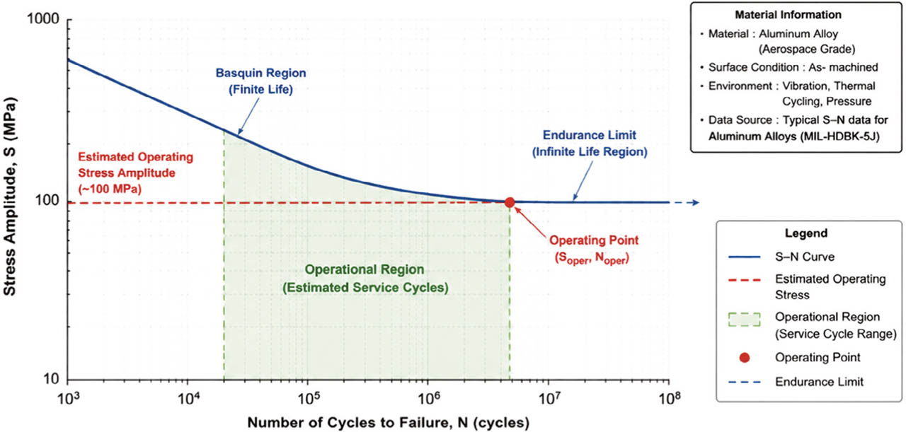
Fig. 4.
S–N curve with operational region highlighted.
A stress amplitude of approximately 95 MPa was used to represent localized cyclic loading in the engine nacelle environment. The estimated fatigue behavior was within the order of the observed operational exposure of 5,642 flight cycles. This result suggests that the outlet discharge component was operating in a fatigue-sensitive regime, where increases in vibration intensity, resonance, or thermal stress could accelerate crack initiation and early propagation. Because the exact high-cycle fatigue response depends on alloy type, geometry, notch condition, residual stress, and loading ratio, this result should be interpreted as a semi-quantitative assessment of fatigue plausibility rather than a deterministic fatigue-life prediction (Fang et al., 2017; Khashaba & Alssayegh, 2025).
3.3. Stress Intensity Factor and Crack Growth Analysis
Crack propagation was evaluated using the Paris Law approach described in the Methodology. As shown in Figure 5a, the observed defect was idealized as a small edge crack subjected to tensile cyclic loading. The stress-intensity-factor range was estimated using a standard edge-crack approximation with a geometry correction factor of Y = 1.12, corresponding to a small edge crack in a semi-infinite plate under uniform tensile stress (Tada et al., 2000; Anderson, 2017). The value was used as a first-order approximation to represent the observed defect because detailed crack geometry and finite-element stress analysis were unavailable. Paris-type crack-growth relations are widely used in aerospace fatigue crack-growth and damage-tolerance analyses, including studies involving aluminum alloys and advanced joint structures under cyclic loading (Fang et al., 2017; Muhammad et al., 2021; Uygur, 2024; Bai et al., 2025).
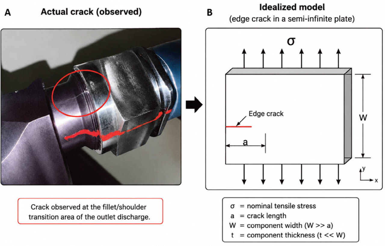
Fig. 5a.
Comparison between the observed crack (A) on the outlet discharge component and the simplified edge-crack model (B) used to estimate the stress intensity factor. The crack was located at the fillet/shoulder transition region and exhibited an approximate visible length of 5 mm.
Using the parameters defined in the Methodology, the analysis considered a stress amplitude of 95 MPa, an initial crack length of 1.0 mm, Paris Law constants of C = 2.5 × 10⁻¹¹ and m = 3.2, and a geometry correction factor of Y = 1.12. These assumptions were used to evaluate the plausibility of fatigue-driven crack propagation rather than to produce a certified life-prediction model.
The MATLAB simulation produced a nonlinear crack-growth trend from 1.0 mm to approximately 5.0 mm after about 5,500 cycles (Figure 5b). At approximately 5,000 cycles, the crack length reached about 4.0 mm. The predicted crack size is comparable to the observed defect of approximately 5 mm at the verified aircraft exposure of 5,642 flight cycles and 10,834 flight hours. This result suggests that fatigue-driven crack propagation is physically plausible under the assumed loading and material conditions.
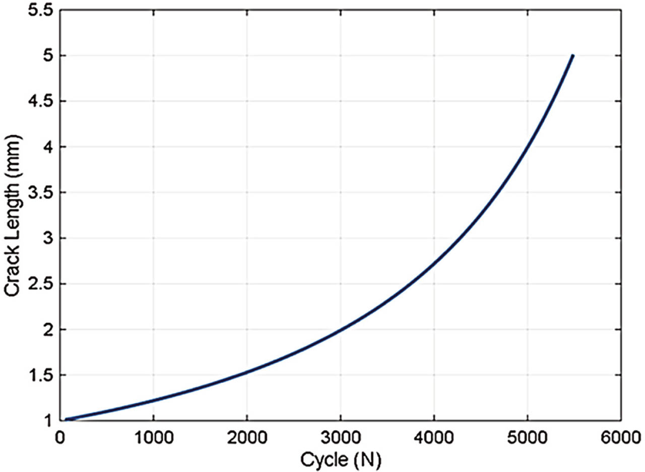
Fig. 5b.
Crack-growth curve obtained from MATLAB-based Paris Law simulation under elevated cyclic loading conditions.
The results support the plausibility of fatigue-driven crack propagation under cyclic loading. Because the material properties and crack geometry were based on representative assumptions, fatigue is considered the most plausible mechanism. However, it cannot be confirmed as the sole cause without fractographic examination, detailed material characterization, or additional non-destructive testing. The close agreement between the predicted crack growth (approximately 5,500 cycles) and the verified aircraft operational exposure (5,642 flight cycles) provides additional physical support for the proposed fatigue interpretation, although the simulation should not be interpreted as a certified remaining-life prediction.
3.4. Safety Factor Evaluation and Failure Mechanism
The structural safety margin was evaluated using a simplified safety factor calculation. The allowable stress used in the estimation was 120 MPa, while the operational stress was set at 95 MPa to maintain consistency with the stress amplitude used in the fatigue and crack-growth analysis. The resulting safety factor was approximately 1.2, indicating a critical or near-limit condition with limited remaining margin. The safety-factor results are summarized in Table 2.
Table 2.
Safety factor estimation results.
| Parameter | Estimated Value |
|---|---|
| Allowable Stress | 120 MPa |
| Operational Stress | 95 MPa |
| Safety Factor (SF) | 1.2 |
| Condition | Critical / Near Limit |
The calculated safety factor was interpreted in relation to the observed crack and the safety-critical function of the outlet discharge component. Because the component already contained a visible defect, the margin was considered reduced under repeated vibration and thermal cycling. This interpretation is consistent with aerospace safe-life and damage-tolerance assessment, in which defect condition, operational exposure, and component criticality are considered together rather than relying solely on a fixed design factor (Shekhter et al., 2015; Moroney & Verma, 2023; Delpuech et al., 2024; Khashaba & Alssayegh, 2025).
The observed failure mechanism was interpreted as a combined effect of fatigue, vibration-induced stress, and thermal stress. As illustrated in Figure 6, microcracks may initiate under cyclic loading and then propagate gradually under continued service exposure. Thermal expansion and contraction may further intensify local stress near geometric transitions or constrained areas, while vibration and resonance may increase cyclic stress amplitude. This interpretation is consistent with studies on thermo-vibration coupling, vibration fatigue, and aerospace material fracture, which show that vibration, resonance, thermal expansion, and stress concentration may interact in crack initiation and propagation (Fang et al., 2017; Muhammad et al., 2021; He et al., 2023; Liu et al., 2024; Hui et al., 2025).
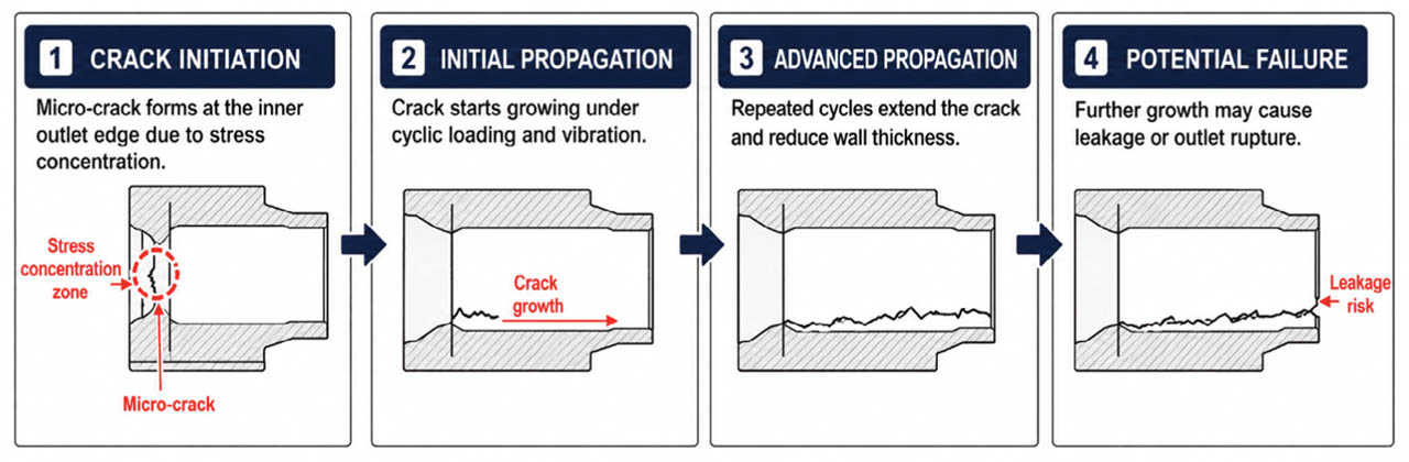
Fig. 6.
Schematic of crack initiation and propagation mechanism.
3.5. System Reliability, FMEA, Corrective Maintenance, and Synthesis
The crack posed a risk of leakage in the fire-extinguishing-agent distribution system. Leakage at the outlet discharge may reduce discharge pressure and decrease the quantity of extinguishing agent delivered to the engine nacelle during emergency operation. Because the engine fire extinguisher system performs a safety-critical function, cracking at this location may reduce system reliability and fire-suppression effectiveness. Similar leakage-related degradation in aircraft fluid or suppression systems has been associated with pressure loss, impaired functional delivery, and reduced reliability (Čerňan et al., 2019; He et al., 2023; Sha et al., 2024; Hui et al., 2025).
The comparative FMEA results are presented in Table 3. The outlet discharge crack had the highest Risk Priority Number (RPN) of 270, based on severity = 9, occurrence = 6, and detection = 5. By comparison, blockage in distribution piping resulted in an RPN of 112, while pressure loss in the extinguisher bottle resulted in an RPN of 90. These results indicate that the outlet discharge crack required the highest maintenance priority among the evaluated failure modes. Although universal aerospace FMEA thresholds are not consistently documented, risk prioritization in maintenance practice is commonly supported by failure-case analysis, safe-life assessment, damage-tolerance principles, and remaining-life considerations (Lv et al., 2020; Nikishkov et al., 2021; Moroney & Verma, 2023; Delpuech et al., 2024; Khashaba & Alssayegh, 2025).
Table 3.
FMEA results with RPN values.
| Component | Failure Mode | Cause | Effect | S | O | D | RPN | Mitigation |
|---|---|---|---|---|---|---|---|---|
| Outlet Discharge | Crack | Fatigue, vibration, thermal | Leakage | 9 | 6 | 5 | 270 | Replacement |
| Distribution Piping | Blockage | Debris | Flow restriction | 7 | 4 | 4 | 112 | Cleaning |
| Extinguisher Bottle | Pressure loss | Seal failure | System failure | 10 | 3 | 3 | 90 | Inspection |
Corrective maintenance was performed by replacing the cracked outlet discharge component with a serviceable unit through the robbing method. After replacement, an operational test was performed to verify system functionality, as shown in Figure 7. For confidentiality and ethical reporting purposes, Figure 7(a) presents only a cropped excerpt of the approved task card, while operationally sensitive information has been omitted. The test confirmed that the system returned to a serviceable condition, with no observable leakage and normal flow characteristics. These results support component replacement as an appropriate corrective action when a structural defect affects a safety-critical fire-extinguishing distribution component. This decision is consistent with damage-tolerance and reliability-based maintenance frameworks, which support replacement or refurbishment when a detected damage state threatens design margin or system safety (Shekhter et al., 2015; Lv et al., 2020; Moroney & Verma, 2023; Khashaba & Alssayegh, 2025).
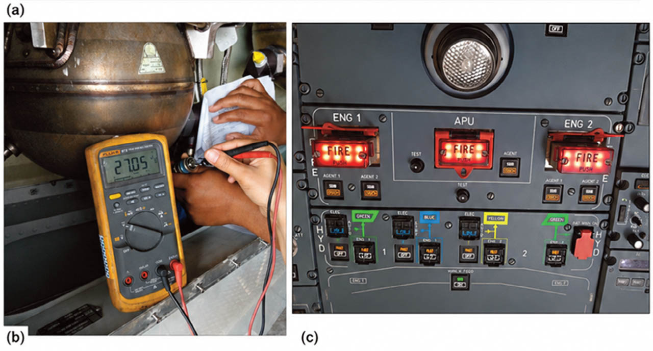
Fig. 7.
Post-maintenance functional test sequence of the fire extinguisher system: (a) cropped excerpt of the approved task card used as the maintenance reference; (b) verification process performed on the aircraft; and (c) normal cockpit fire panel indication confirming system serviceability.
Overall, the results support fatigue-induced crack propagation as the most plausible failure mechanism based on the available inspection evidence, operational exposure, S–N interpretation, Paris Law simulation, safety factor evaluation, and FMEA ranking. The outlet discharge crack represented a critical structural degradation because it combined a limited safety margin, a high RPN value, and a direct risk of leakage in a safety-critical fire extinguisher distribution path.
| ACTION | RESULT |
|---|---|
1. On the ENG/FIRE control panel 255VU:
|
|
2. On the ENG/FIRE control panel 255VU:
|
|
4. DISCUSSION
The combined inspection evidence, fatigue assessment, and simulation results consistently point to fatigue-induced crack propagation as the dominant failure mechanism in the outlet discharge component. The crack was found in Zone 420, an engine nacelle area exposed to repeated vibration, temperature fluctuation, and operational loading. These conditions are consistent with high-cycle fatigue, in which repeated low-amplitude and high-frequency loading can initiate microcracks and promote gradual crack growth. Although the crack length was less than 5 mm, its location in the fire-extinguishing-agent distribution path made it important for reliability and airworthiness, as leakage may reduce discharge pressure and impair extinguishing-agent delivery during emergency operation.
The observed crack morphology and service exposure were consistent with fatigue behavior, although they did not provide definitive forensic proof. The aircraft had accumulated approximately 5,642 flight cycles and 10,834 flight hours when the crack was detected, indicating repeated cyclic loading over an extended service period. The apparent crack orientation was also compatible with a stress-influenced defect. However, because no fractography, dye penetrant testing, ultrasonic inspection, or microscopic material characterization was performed, fatigue could not be confirmed as the sole cause. Previous studies have shown that fatigue cracks in aerospace materials may follow local stress fields, stress concentrations, and microstructural or geometry-driven paths under vibration and cyclic loading (Muhammad et al., 2021; He et al., 2023; Hui et al., 2025). Published failure reports specific to this exact component remain limited; however, EASA AD 2025-0034 documents A330 fire-extinguisher discharge-outlet cracking associated with heat-treatment susceptibility to stress corrosion cracking, supporting crack susceptibility as a relevant maintenance concern (EASA, 2025).
The semi-quantitative fatigue and crack-growth assessments further support this interpretation. A stress amplitude of approximately 95 MPa was used to represent localized vibration-induced cyclic loading on the outlet discharge component. Although this value was not obtained from direct strain measurement, it provided a representative engineering basis for comparing fatigue behavior with the verified service exposure. The estimated fatigue response aligned with the 5,642-flight-cycle record, indicating that crack initiation and early propagation could plausibly occur during the observed operating period. This interpretation is consistent with the stress-life concept, in which fatigue life decreases as cyclic stress amplitude increases, and with the use of S–N curves and Basquin-type relations in high-cycle fatigue assessment (Fang et al., 2017; Khashaba & Alssayegh, 2025).
The Paris Law-based simulation provided a physically consistent fracture-mechanics explanation for the detected defect. The model predicted nonlinear crack growth from 1.00 mm to approximately 5.00 mm after about 5,500 cycles, which was comparable with the verified aircraft exposure at inspection. The increasing crack-growth rate indicated accelerated propagation as crack length increased, consistent with the rise in stress intensity factor at larger crack sizes. However, the simulation should be interpreted as a semi-quantitative plausibility assessment rather than an exact remaining-life prediction, because the material properties, stress amplitude, and geometry correction factor were treated as representative assumptions.
Vibration-induced stress and thermal stress likely acted as accelerating factors. The outlet discharge component is installed in the engine nacelle, where continuous excitation from engine operation can impose repeated loading on fittings, joints, and discharge components. Resonance may amplify local cyclic stress when excitation frequency approaches the natural frequency of the component or its support structure. At the same time, thermal cycling may intensify local stress near joints, geometric transitions, or constrained interfaces. Studies on thermo-vibration fatigue and aerospace material damage show that vibration, resonance, thermal expansion, and stress concentration can interact to drive crack initiation and propagation (Muhammad et al., 2021; He et al., 2023; Liu et al., 2024; Hui et al., 2025).
The safety factor evaluation indicated a limited remaining structural margin. Using an allowable stress of 120 MPa and an operational stress of 95 MPa, the calculated safety factor was approximately 1.2, suggesting a near-limit condition rather than a large stress reserve. In the presence of a visible crack, this margin becomes more critical because local crack-tip stress concentration may reduce effective fatigue resistance. Aerospace damage-tolerance practice emphasizes that the safety margin should be interpreted in relation to the defect state, service exposure, component function, and reliability requirements rather than as a universal numerical threshold (Shekhter et al., 2015; Moroney & Verma, 2023; Delpuech et al., 2024; Khashaba & Alssayegh, 2025).
The crack also had direct implications for system reliability. Because the outlet discharge forms part of the extinguishing-agent distribution path, cracking may cause leakage, reduce discharge pressure, and decrease agent delivery to the engine nacelle. Although the component is passive during normal operation, it becomes essential when the fire protection system is activated. Leakage-related degradation in aircraft fluid or suppression systems has been associated with pressure loss, reduced delivery capability, lower reliability, and safety concerns (Čerňan et al., 2019; He et al., 2023; Sha et al., 2024; Hui et al., 2025).
The FMEA results supported this reliability-based interpretation. The outlet discharge crack produced the highest Risk Priority Number, RPN = 270, compared with distribution piping blockage, RPN = 112, and extinguisher bottle pressure loss, RPN = 90. The high severity score reflected the fire extinguisher system's safety-critical function. In contrast, the occurrence and detection scores reflected the plausibility of fatigue-related mechanisms and the difficulty of detecting small cracks before they become functionally significant. Although standardized RPN thresholds are not consistently reported across aerospace literature, maintenance prioritization is commonly guided by failure consequence, residual life, inspection detectability, and damage-tolerance considerations (Lv et al., 2020; Nikishkov et al., 2021; Moroney & Verma, 2023; Delpuech et al., 2024; Khashaba & Alssayegh, 2025). Based on this, the outlet discharge crack required the highest maintenance priority among the evaluated failure modes.
Corrective maintenance through component replacement was therefore appropriate. The damaged outlet discharge component was replaced with a serviceable unit through the robbing method, and the subsequent operational test confirmed restored serviceability, with no observable leakage and normal flow characteristics. This result supports replacement as an appropriate corrective action when a structural defect affects a safety-critical fire-extinguishing distribution component. Damage-tolerance and reliability-based maintenance frameworks similarly support repair, refurbishment, or replacement when detected damage threatens design margin or system safety (Shekhter et al., 2015; Moroney & Verma, 2023; Khashaba & Alssayegh, 2025).
Overall, the integration of inspection evidence, fatigue estimation, Paris Law simulation, safety factor analysis, and FMEA provides a practical framework for aircraft maintenance decision-making when complete experimental data are unavailable. This framework links component-level damage to system-level maintenance priority and supports inspection-based corrective action. Similar durability-damage-tolerance and service-data-based approaches have been used to guide residual-life interpretation and maintenance planning in damage-sensitive structures (Nikishkov et al., 2021; Wileman et al., 2021; Moroney & Verma, 2023; Delpuech et al., 2024).
This study has several limitations that should be noted when interpreting the findings. The crack was detected visually, and no dye penetrant testing, ultrasonic testing, fractography, microscopic material characterization, or high-fidelity finite element analysis was conducted. Therefore, crack depth, crack-tip morphology, fracture surface features, material condition, local stress concentration, and crack-tip stress intensity were not directly verified. The material was assumed to be a representative aerospace-grade aluminum alloy, while the fatigue parameters were not component-specific. Fatigue resistance and fracture toughness may vary with material system and microstructural characteristics (Naveen et al., 2025). The analysis should be interpreted as a qualitative and semi-quantitative failure assessment rather than a definitive fatigue-life certification.
Future work should combine non-destructive testing, fractographic and metallurgical analysis, finite element analysis, and long-term reliability data to validate the crack mechanism and improve fatigue-life prediction. Structural health monitoring methods, including guided-wave, distributed fiber Bragg grating, and other sensor-based techniques, may support earlier detection of defects in vibration-sensitive aircraft piping and structural components (Huang et al., 2016; Li, 2025). With sufficient service and material datasets, data-driven fatigue-life prediction may also complement physics-based crack-growth assessment (Gbagba et al., 2023).
5. CONCLUSIONS
This study investigated a crack detected on the outlet discharge component of an Airbus A330-900 engine fire extinguisher system during C-Check maintenance. Although the crack was less than 5 mm long, its position in the extinguishing-agent distribution path made it significant because leakage could reduce discharge pressure, limit agent delivery, and compromise fire-suppression effectiveness during emergency operation. The available inspection evidence and semi-quantitative assessment support fatigue-induced crack propagation as the most plausible mechanism, with repeated cyclic loading, vibration-induced stress, and thermal cycling in the engine nacelle acting as accelerating factors.
The verified aircraft exposure of 5,642 flight cycles was consistent with the high-cycle fatigue interpretation and MATLAB-based Paris Law simulation. The simulation predicted nonlinear crack growth from 1.00 mm to approximately 5.00 mm after about 5,500 cycles, comparable with the observed defect and operational exposure. The safety factor evaluation yielded SF = 1.2, indicating a near-limit structural condition, while the FMEA identified the outlet discharge crack as the highest-priority failure mode with an RPN of 270.
Corrective maintenance through component replacement restored system serviceability, as confirmed by post-replacement operational testing with no observable leakage and normal flow characteristics. This case demonstrates that combining inspection evidence, fatigue interpretation, Paris Law simulation, safety factor evaluation, and FMEA can support reliability-based maintenance decisions when detailed material testing, advanced non-destructive testing, and finite element analysis are unavailable. Future work should incorporate non-destructive testing, fractography, material characterization, finite element analysis, and long-term reliability data to improve crack-mechanism validation and fatigue-life prediction.
Notes
[1] Declaration of Competing Interest: The authors certify that there are no financial conflicts of interest or personal relationships that could have influenced the study reported in this paper.
[4] Declaration of Generative AI and AI-assisted technologies in the writing process: During the preparation of this work, the authors used ChatGPT to enhance the clarity of the writing. After using ChatGPT, the authors reviewed and edited the content as needed and took full responsibility for the publication's content.