
Nomenclature
| symbols | Designations | symbols | Designations |
|---|---|---|---|
| da/dN | Crack growth rate (m/cycle) | Qi | Energy dissipated per cycle i |
| A | a dimensionless constant | Qenv | Enclosed energy (total area enclosed by all the cycles) |
| A | Elongation (%) | R | Load Ratio |
| B | Thickness (mm) | S1, S2 | Ductile and brittle Striations |
| D1, D2 | Dimples | US | Specific energy (J/m2) |
| Kmin, Kmax | Minimal and maximal stress intensity factor (MPa.m1/2) | W | Width (mm) |
| K′ | Cyclic strength coefficient (MPa) | α | The maximum specimen compliance during a cycle and Po |
| ΔK | Amplitude stress intensity factor (MPa.m1/2) | δ, δ′ | Crack opening displacement (mm) and differential crack opening (mm) |
| L | Length (mm) | γ | Energy necessary for creating surface (J/m2) |
| n | Hardening coefficient | μ | Shear modulus, MPa |
| Pmin, Pmax | Minimum and maximum load (N) | σc | Critical stress at fracture MPa |
| Po | Crack opening load (N) | σu | Ultimate tensile strength (MPa) |
| Q | hysteretic energy dissipated (J/cycle) | σy | yield stress (MPa) |
Table 1a.
Nominal composition of the aluminum alloy 2024 T351.
| Element | Si | Fe | Cu | Mn | Mg | Cr | Zn | Ti | Al |
| Mean % | 0.90 | 0.22 | 4.46 | 0.66 | 1.5 | 0.01 | 0.04 | 0.02 | rest |
Table 1b.
Mechanical properties of the aluminum alloy 2024 T351.
| yield stress (MPa) | ultimate tensile strength (MPa) | elongation (%) | cyclic strength coefficient, K′ (MPa) | Hardening coefficient, n |
| 318 | 524 | 12.8 | 652 | 0.104 |
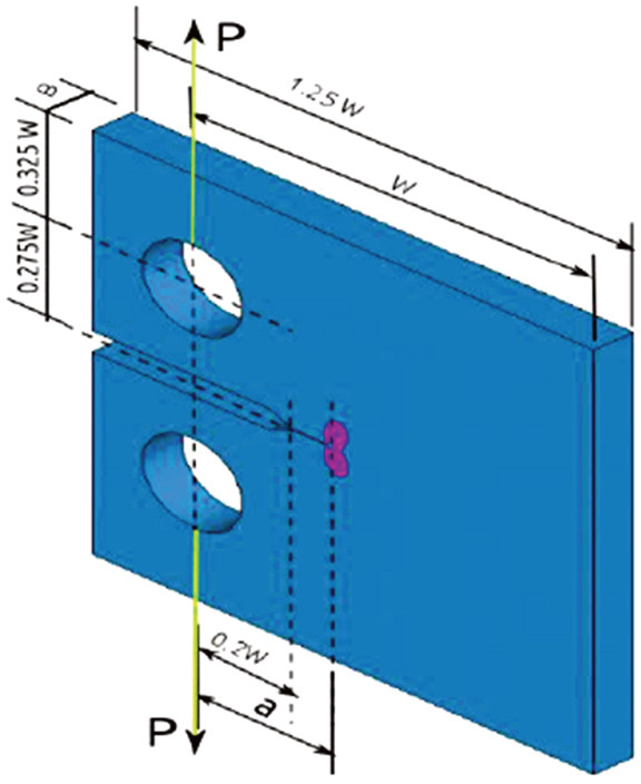
Figure 1.
Schematic of a compact tension specimen.
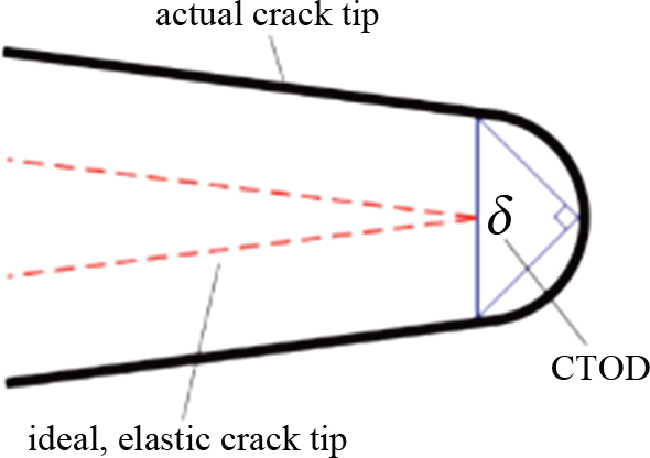
Figure 2.
Schematic of crack opening displacement δ.
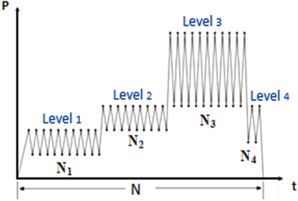
Figure 3.
Reduced spectrum studied.
Table 2.
Loading conditions under constant amplitude loading.
| R | 0.01 | 0.10 | 0.33 | 0.54 | 0.70 | |||
|---|---|---|---|---|---|---|---|---|
| Pmin (daN) | 4 | 6 | 40 | 50 | 158 | 178 | 324 | 588 |
| Pmax (daN) | 400 | 600 | 400 | 500 | 480 | 540 | 600 | 840 |
| ΔP (daN) | 396 | 594 | 360 | 450 | 322 | 362 | 276 | 252 |
Table 3.
Different load levels with specific steps.
| Type of spectrum | Level 1 Pmin = 80 daN Pmax = 150 daN R=0.53 | Level 2 Pmin = 160 daN Pmax = 392 daN R = 0.41 | Level 3 Pmin = 323 daN Pmax = 600 daN R = 0.54 | Level 4 Pmin = 138 daN Pmax = 323 daN R = 0.43 |
|---|---|---|---|---|
| N1 | N2 | N3 | N4 | |
| A | 1 | 1 | 1 | 1 |
| B | 10 | 10 | 10 | 2 |
| C | 10 | 10 | 50 | 2 |
| D | 10 | 10 | 100 | 2 |
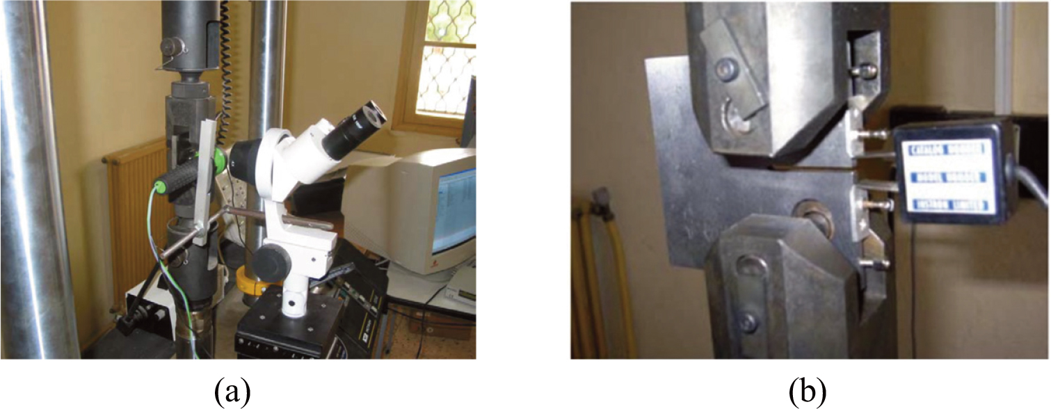
Figure 4.
(a) Testing machine; (b) crack opening displacement gauge (CODG).
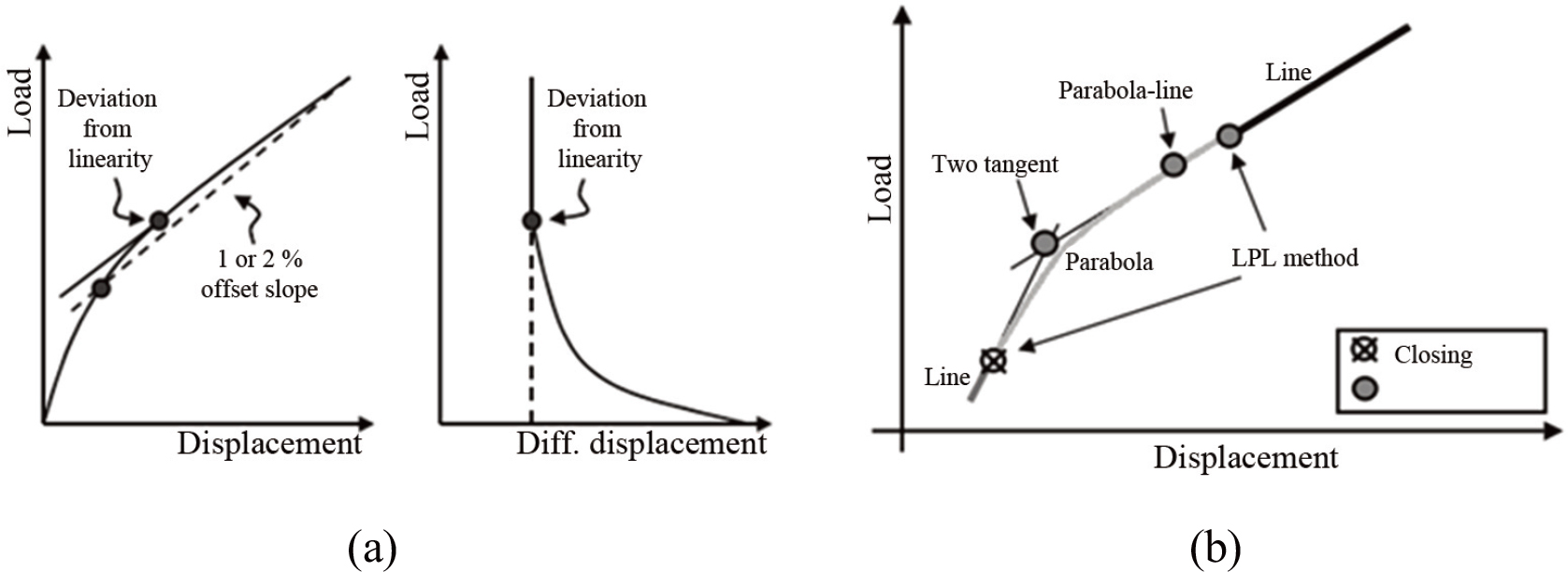
Figure 5.
(a) Schematic diagram of P – δ and P – δ′; (b) curve fitting method (Stoychev & Kajawski, 2003).
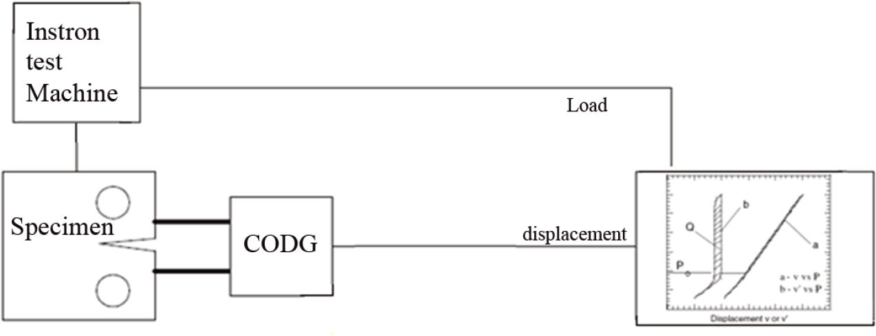
Figure 6.
Crack closure measurement system.
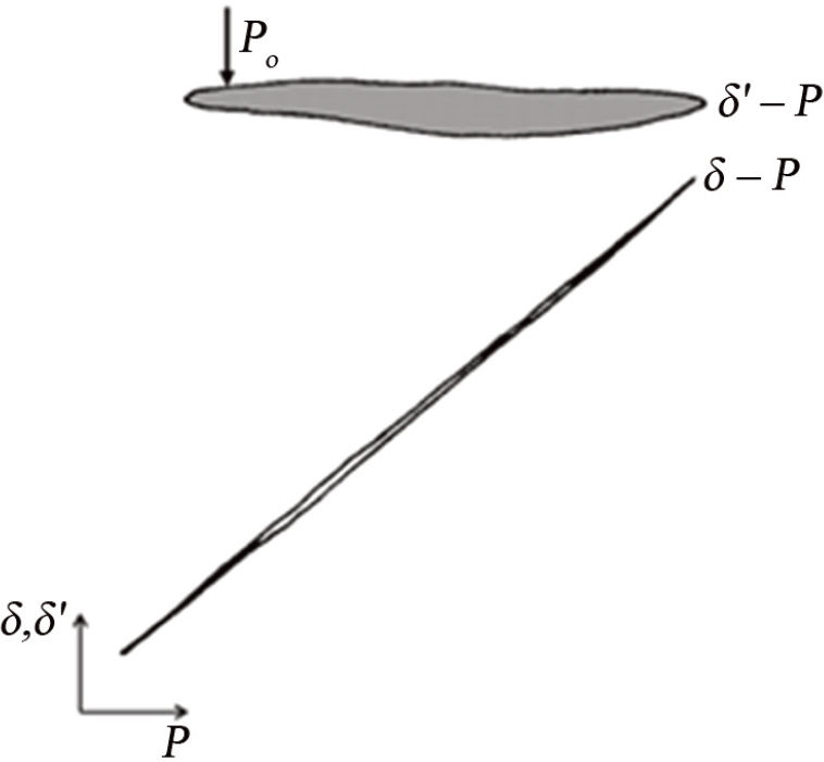
Figure 7.
Diagram P–δ hysteresis energy measurements under CAL (Benguediab, 1989).
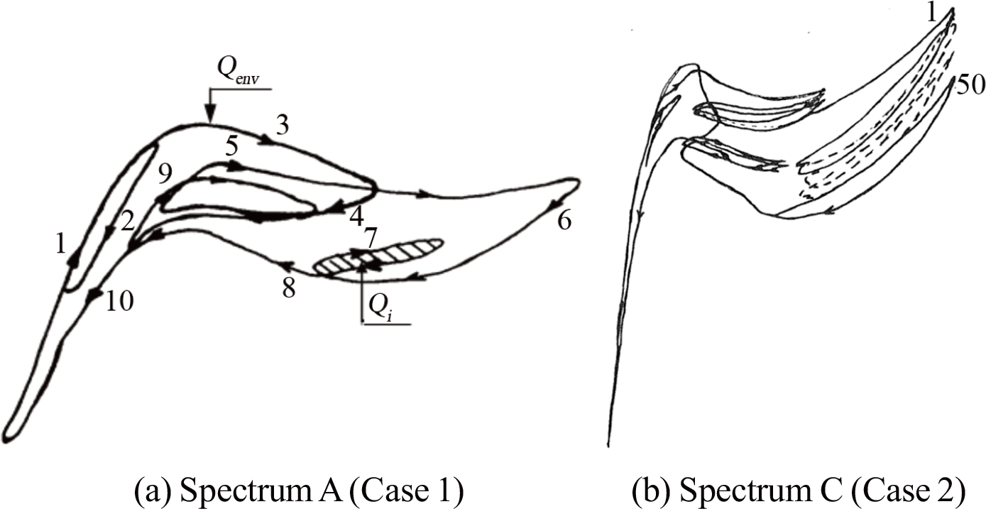
Figure 8.
Diagram P – δ hysteresis energy measurements under VAL; (a) Sp. A. (b) Sp. C (Benguediab, 1989).

Figure 9.
(a) 1 – Ductile striations S1, 2 – brittle striations S2, 5 – Dimples D2; (b) 3 – Quasi-cleavage, 4 – Dimples D1.
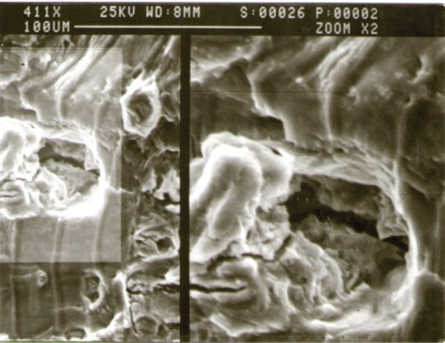
Figure 10.
Example of typical dimple D2, with magnified inset.
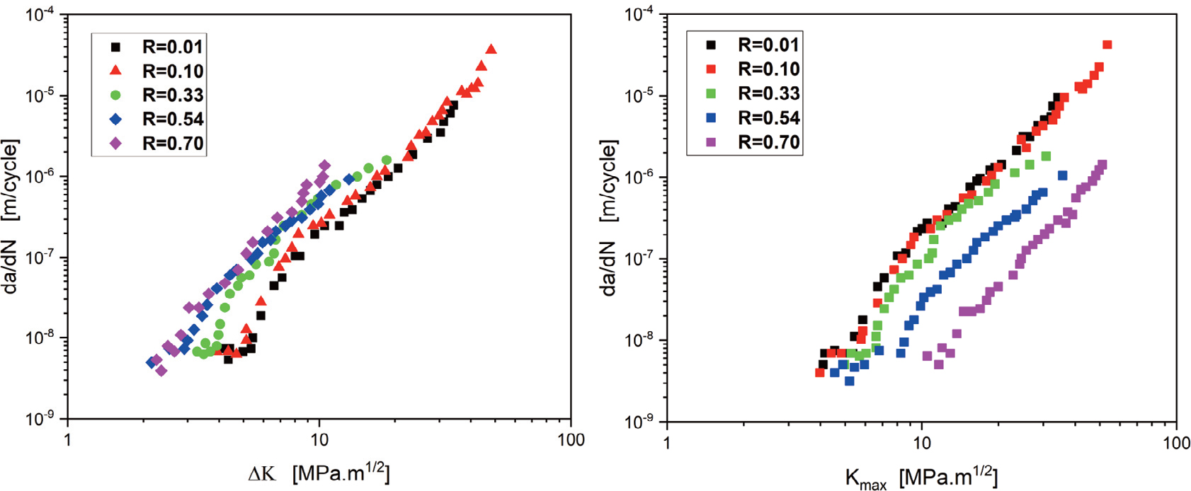
Figure 11.
The relation between da/dN vs. ∆ K and between da/dN vs. Kmax.
Table 4.
Transition-related parameters.
| R | 0.01 | 0.10 | 0.33 | 0.54 | 0.70 | |
|---|---|---|---|---|---|---|
| T1 | ΔK | 8 | 7.5 | 6 | 6 | 5 |
| Kmax | 8.5 | 8.5 | 9 | 12 | 15 | |
| da/dN | 10−8 | 10−8 | 8 × 10⁻⁹ | 7.5 × 10⁻⁹ | 8 × 10⁻⁹ | |
| T2 | ΔK | 12 | 11 | 9 | 7 | 7 |
| Kmax | 12 | 12 | 12 | 15 | 23.3 | |
| da/dN | 1.30 × 10⁻⁷ | 1.30 × 10⁻⁷ | 1.70 × 10⁻⁷ | 7.2 × 10⁻⁸ | 2 × 10⁻⁷ | |
| T3 | ΔK | 19.8 | 18 | 21 | 13 | 12 |
| Kmax | 20 | 20 | 31 | 28 | 37 | |
| da/dN | 3 × 10⁻⁶ | 3 × 10⁻⁶ | 1.6 × 10⁻⁶ | 7 × 10⁻⁷ | 4 × 10⁻⁷ | |
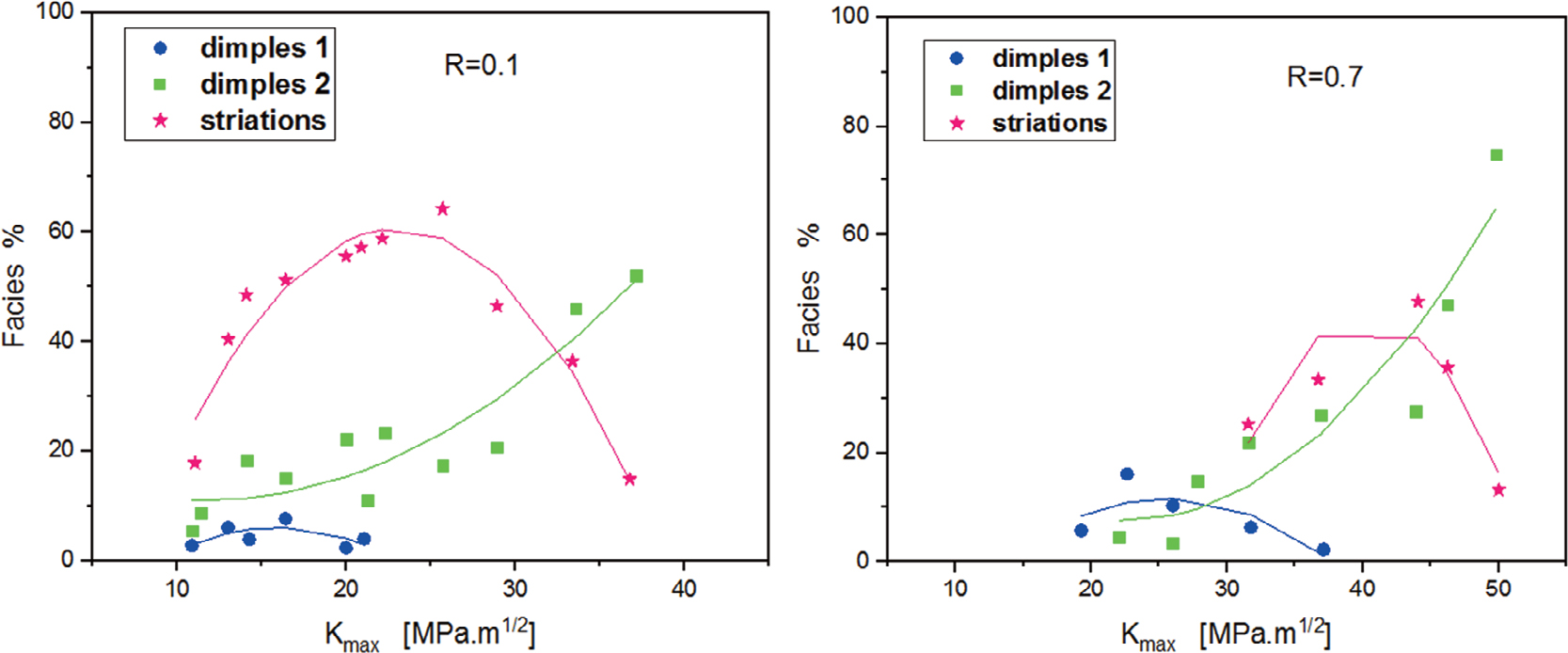
Figure 12.
Area distribution of striations and dimples.
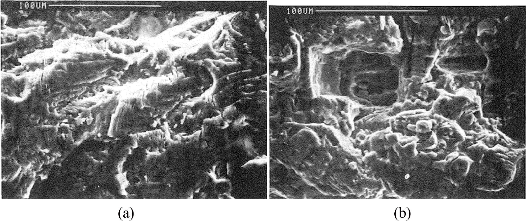
Figure 13.
Repartition of features at da/dN = 5 × 10⁻⁷m/cycle; (a) R=0.10; (b) R=0.70.
Table 5.
Repartition of features at da/dN = 5 × 10⁻⁷ m/cycle.
| R | 0.10 | 0.70 |
|---|---|---|
| % Striations | 60 | 30 |
| % Dimples | 15 | 30 |
| Kmax [MPa.m1/2] | 13 | 31.27 |
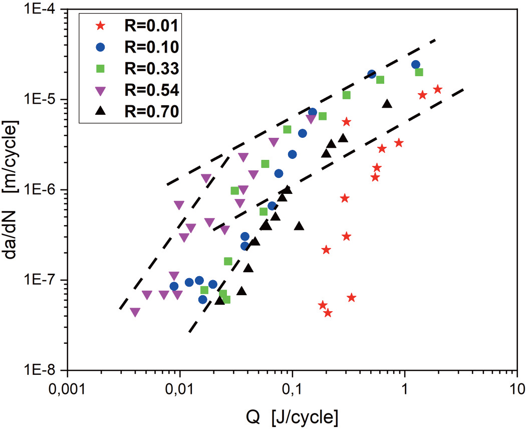
Figure 14.
Evolution of the crack growth rate da/dN vs. the energy dissipated Q.
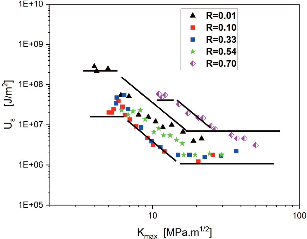
Figure 15.
Evolution of the energy dissipated per cycle vs. Kmax.
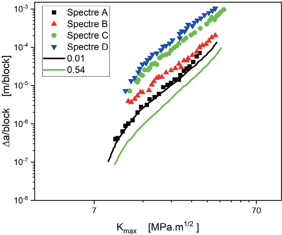
Figure 16.
Δa/block vs. Kmax.
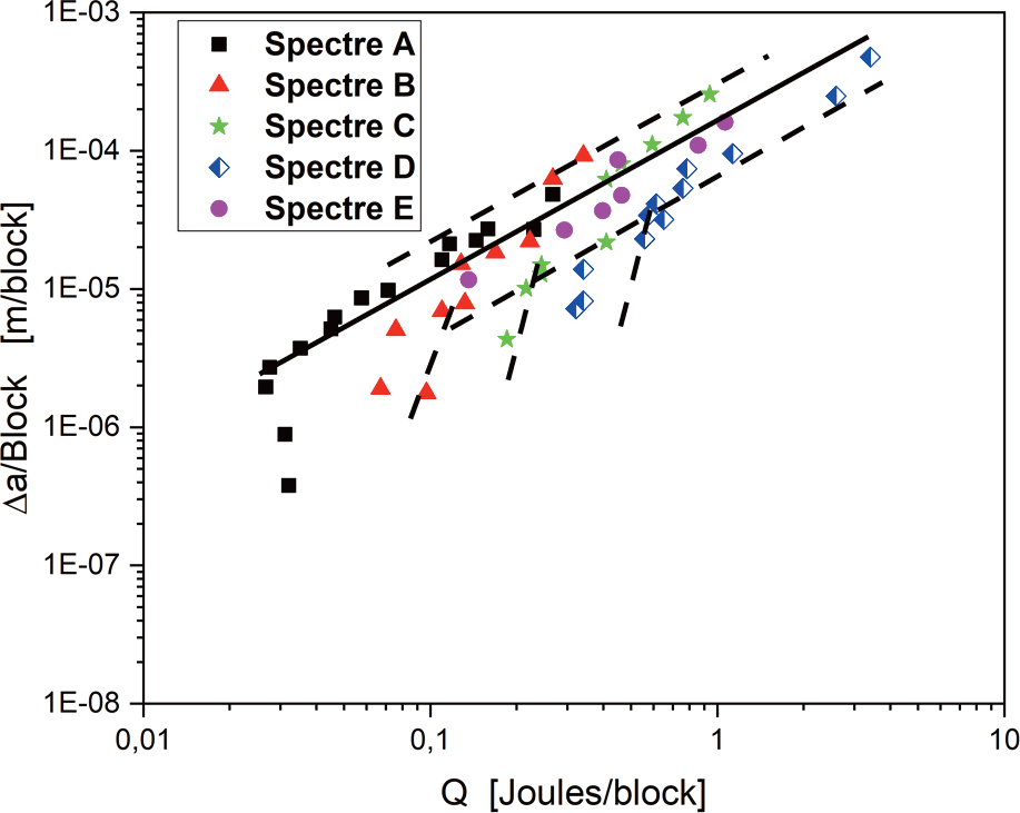
Figure 17.
Evolution of the crack growth rate da/block vs. the energy dissipated Q.
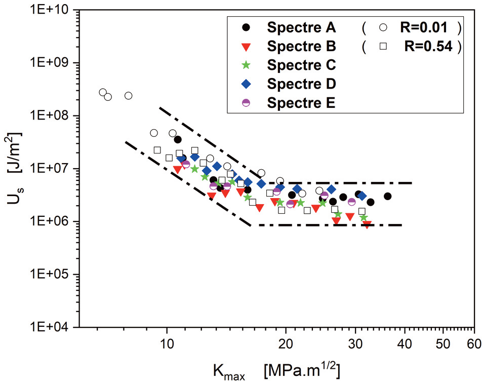
Figure 18.
Evolution of US with respect to Kmax.
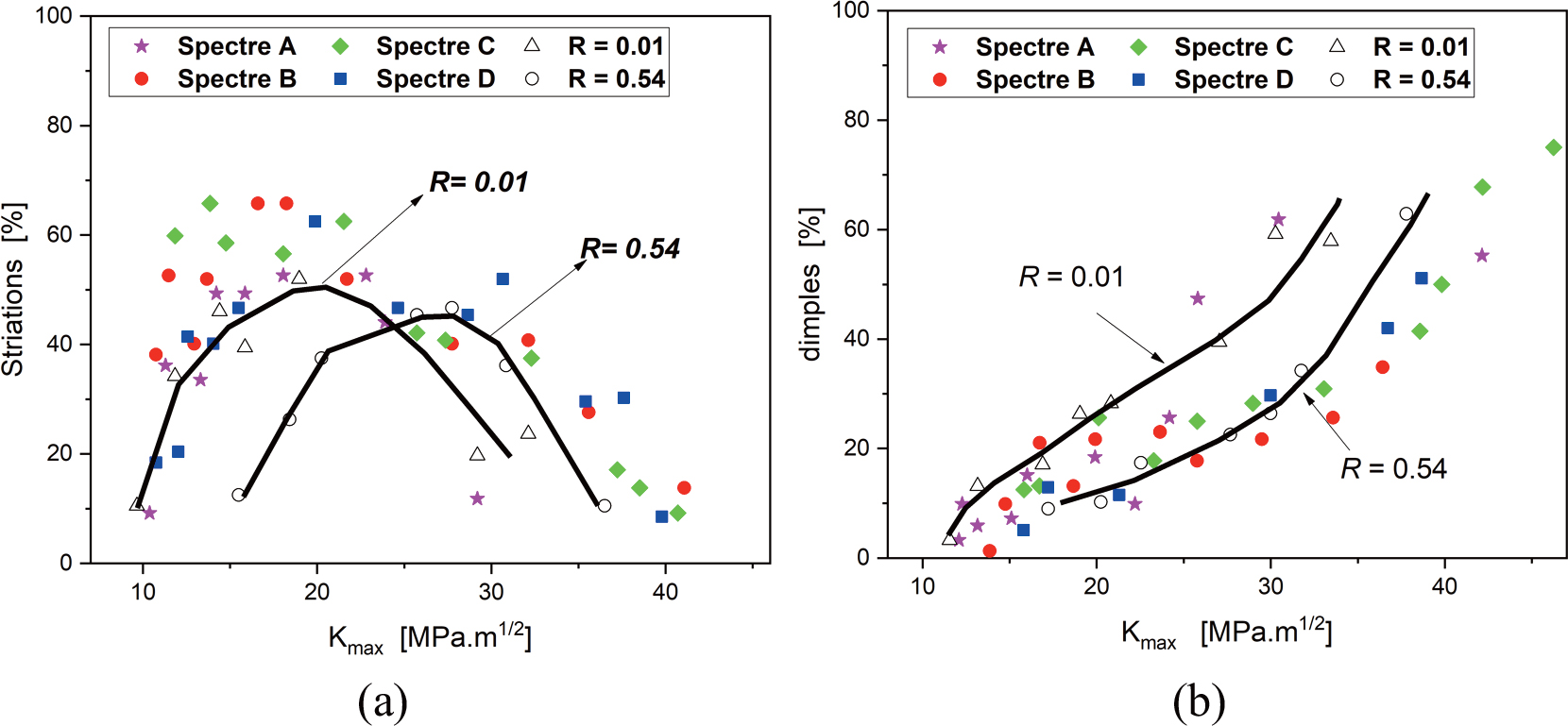
Figure 19.
Area distribution of fractographic characteristics: (a) striations; (b) dimples.
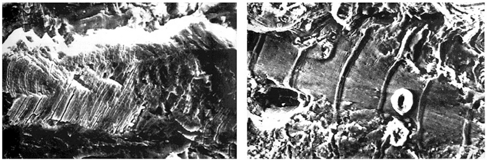
Figure 20.
Slip markings observed at low Kmax values (Kmax=13.50 MPa.m1/2 Spectrum D).
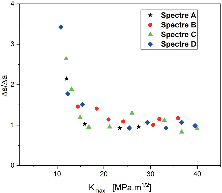
Figure 20.
Ratio of Δs (spacing between markings) to Δa (macroscopic crack advance) as function of Kmax for VAL tests.
Table 6.
Lifespan in number of blocks and relative error.
| Block | Number of blocks | Error (%) | |
|---|---|---|---|
| A | Measured Maachou et al. (2016) Present model Elber (1976) | 75120 68323 69454 92981 | - 9.04 7.54 23.77 |
| B | Measured Maachou et al. (2016) Present model Elber (1976) | 23900 11196 26161 31060 | - 53.15 9.46 29.95 |
| C | Measured Maachou et al. (2016) Present model Elber (1976) | 9600 11153 10208 10713 | - 16.17 6.33 11.60 |
| D | Measured Maachou et al. (2016) Present model Elber (1976) | 5500 3670 5151 5883 | - 33.27 6.35 6.96 |