

1. Introduction
Glass fibers are widely incorporated into concrete mixtures to enhance tensile strength and mitigate shrinkage cracking. However, the highly alkaline environment of concrete degrades glass fiber strength. Glass fiber degradation is due to the high alkalinity of cement after hydration, when calcium hydroxide, Ca(OH)2, forms during cement hydration. Ca(OH)2 increases the pH value to between 12 and 13. The highly alkaline environment causes rapid deterioration of glass fibers; the chemical reaction, as shown in Equations 1 and 2, between the hydroxide ion (OH1) and silicon in glass can cause debonding between glass and cement (Chen et al. 2007).
The formation of Si-OH, as shown on the right side of Equation 2, produces a gel type that has low density. In addition, this gel will cause a degradation of the strength of the fiber and also cause an increase in the diffusion of water and alkali; this will accelerate the degradation of glass fiber (Kamal and Boulfiza, 2011).
To prevent this degradation, glass fiber surfaces are encapsulated with various types of coatings. These coatings could be organic, inorganic, nano-engineered, and hybrid composite coatings. Gao et al. 2004 investigated the use of polymer coating for alkali-resistant glass fibers. The results revealed that the use of polymer coating enhances durability through increased corrosion resistance to alkali and fracture energy absorption capability of its composites. In addition to the durability enhancement, the polymer coating caused an increase in the tensile strength of glass fiber and also increased the adhesion between glass fiber and cementitious matrices through the pull-out test.
Kempis and Orlowsky 2024 evaluated the durability of treated alkali-resistant glass filaments. The treatment of alkali-resistant glass filaments was achieved by using co-polymerized styrene-butadiene rubbers (CemFil-SBR1 or CemFil-SBR2). The evaluation was based on microstructural analysis using a Scanning Electron Microscope (SEM) and mechanical properties using a uniaxial tensile test. The results showed that the treatment of glass filaments delayed the process of corrosion and enhanced the tensile strength by 21% and 33% for SBR1 and SBR2, respectively, compared to the untreated glass filaments.
In addition to the benefit of coating glass fibers to prevent degradation, Messori et al. 2018 found that coating thickness has a significant impact on the mechanical behaviour. The study used two types of epoxy coating that differed in the hardening agent and coating thickness.
Zhu et al. 2023 studied experimentally the failure mode and tensile properties of reinforced concrete incorporating different volume fractions of epoxy-coated alkali-resistant glass textile. Quasi-static tensile tests were performed on single yarns, fiber strips, and concrete with different volumes of epoxy-coated alkali-resistant glass textile. Warp yarn (0.24%, 0.49%, 0.73%, and 1.09%) and weft yarn (0%, 0.20%, 0.48%, and 0.96%) by volume were incorporated into reinforced concrete. The results evidenced that the tensile properties and failure modes of concrete with different volumes of epoxy-coated alkali-resistant glass textile were primarily dependent on the warp yarn’s volume content and the coating, while the weft yarn’s contribution was negligible. The study proved that the optimization of single fabric configurations may be reached by varying the yarns’ volume fraction and surface treatment.
Yu et al. (2021) experimentally investigated the effect of carbon coating on Glass Fiber Reinforced Polymer (GFRP) under exposure to either distilled water or concrete solution (alkaline solution). The results revealed that the effectiveness of the carbon coating layer mainly depends on the exposure environment. In distilled water, the carbon coat actually increases moisture absorption and diffusion, causing coated GFRP bars to lose more interlaminar shear strength at 60°C than traditional GFRP bars. On the other hand, under exposure to the alkaline solution, the carbon-coated GFRP bars exhibited higher shear strength than the traditional GFRP bars.
Behboud et al. 2023 investigated the chemical and mechanical properties of glass fibers coated with zirconia nanoparticles. The results revealed that the tensile strength of coated glass fibers increased with higher nanoparticle solution concentrations. Furthermore, the coated glass fibers exhibited corrosion resistance even after 500 h of alkaline immersion, thereby preserving their structural integrity. The study found that coating of glass fiber with zirconia nanoparticles can enhance both mechanical strengthening and protection against alkaline degradation.
Arabi et al. 2018 evaluated the durability of alkali-resistant glass fibers under exposure to a highly alkaline cement matrix. Microstructural and mineralogical characterization using SEM/EDX and XRD analyses indicated that zirconia treatment of alkali-resistant glass fibers failed to prevent the degradation of glass fibers. It was found that the use of mineral additives, such as fly ash and silica fume, mitigates the degradation of glass fibers; the reason behind this is the consumption of calcium hydroxide by the pozzolanic reaction.
Bompadre et al. 2021 investigated the use of sodium montmorillonite nanoclay particles in polymer coatings for alkali-resistant glass fibers to improve bonding at the interface. Single-fiber pull-out tests, atomic force microscopy, and microstructural analysis revealed that adding nanoclay did not increase single-fiber tensile strength, which was primarily determined by silane treatment. However, the incorporation of nanoclays into polymer coatings resulted in a significant increase in interfacial shear strength and total pull-out work. The nanoclay particles acted as nucleation sites for hydration products in the contact zone, resulting in enhanced chemical bonding and mechanical interlocking. An increase in surface roughness alone was not sufficient to increase pull-out loads; therefore, chemical interactions and hydration nucleation were found to be the main factors in improving the interfacial bond strength.
Bajaj et al. 2020 studied the effects of coating the surface of polypropylene fibers with supplementary cementitious materials (SCMs), which included silica fume and metakaolin. The microstructural analysis revealed that the SCMs successfully coated the polypropylene fibers. The results showed that the coating enhanced compressive strength but had no measurable impact on flexural strength.
Surface modification can also enhance the mechanical bond between fiber-reinforced polymer reinforcement and concrete. Lu et al. 2021 investigated the bond strength of a ribbed and a sand-coated glass fiber reinforced polymer (GFRP). It was found that the bond strength of the sand-coated bars was superior to that of the ribbed bars.
Devaraj et al. 2023 explored the key parameters that affect the bond behavior of glass fiber reinforced polymer bars with epoxy-bonded sand coatings embedded in concrete. The pull-out tests and microstructural analysis showed that the epoxy-bonded sand layer dominates the initial chemical adhesion and the post-cracking mechanical interlocking. The experimental outcomes also revealed that the concrete compressive strength and sand coating integrity affect the transition of the failure mode from pull-out to concrete shearing. This outcome implies that the efficiency of sand-coated polymer surfaces depends significantly on the mechanical strength of the epoxy interphase and the concrete matrix.
The aforementioned experimental outcomes demonstrate that surface coatings can enhance the durability of glass fibers, alter the fiber-matrix interface, and modify the mechanical bond between fiber-reinforced polymer reinforcement and concrete. Yet, the effect of each function is not necessarily congruent. A coating that enhances the resistance to the alkaline solution might reduce the chemical adhesion, while a rough surface might augment the mechanical interlocking without protecting the underlying glass fibers from the concrete alkalinity. Therefore, the combined influence of an epoxy coating and a sand treatment on the durability of the glass fibers and the mechanical bond between the reinforced polymer and the concrete should be separately assessed.
Even though numerous studies have been conducted on the use of glass fibers in concrete, limited information can be found on the behavior of concrete incorporating epoxy-coated glass fiber strands with or without sand treatment. Particularly, the interaction between the epoxy protection, the sand-induced surface roughness, the strand morphology, and the mechanical performance of concrete has not been adequately established yet. Therefore, this study aims to evaluate the physical and mechanical properties of concrete utilizing the aforementioned strands. In addition, the detailed procedure of coating the glass fibers and producing the epoxy-coated strands is provided.
2. Experimental Work
2.1. Materials
Ordinary Portland Cement (OPC) Type I produced by the Badosh cement plant was utilized in the current study. Tables 1 and 2 illustrate the chemical compositions and physical properties of cement, respectively. The fine aggregate was obtained from the Kanhash River, and the coarse aggregate was obtained from the Tigris River. The specific gravity of fine and coarse aggregates was measured in the saturated surface dry (SSD) condition; the values of specific gravity were 2.6 and 2.65 for fine and coarse aggregates, respectively. The values of absorption were 1.52% and 0.93% for fine and coarse aggregates, respectively. In the current study, three types of glass fibers were used. The first type is the uncoated glass fiber with an approximate diameter of 0.18 mm and a nominal length of 32 mm. The second type is the epoxy-coated glass fiber strands with a nominal length of 32 mm and an approximate diameter of 0.7 mm. The third type is the epoxy-coated and sand-coated glass fiber strands with a nominal length of 32 mm and an approximate diameter of 0.7 mm. The procedure for fabricating the epoxy-coated glass fiber strands is explained in the following paragraph. Table 3 illustrates the properties of uncoated glass fibers and the tensile strength of epoxy-coated glass fiber strands. The main reason for spreading sand particles evenly on the epoxy-coated glass fiber strands is to enhance their interfacial bond strength with concrete.
The fabrication procedure for the epoxy-coated glass fiber strands is illustrated in Figure 1. A 4 m long glass fiber bundle was tensioned and coated with a two-part epoxy system, which is manufactured by Fosroc (2 parts of resin and 1 part of hardener, Nitoplate CPA30) in an environmentally controlled room (Temperature of 23°C±2°C and relative humidity of 50%). To ensure a uniform coating thickness, the excess epoxy was removed, as illustrated in Figure 1b, and then epoxy-coated strands were left in an environmentally controlled room for 24 hours of hardening. After completing the hardening, the epoxy-coated glass fiber strands were cut to the desired length, as shown in Figure 1d. For the third type of epoxy-coated and sand-coated glass fiber strands, after removing the excess epoxy, the sand particles (passing sieve No.100 in oven-dry condition) were evenly spread on the fresh epoxy-coated glass fiber strands. After hardening, the epoxy-coated and sand-coated glass fiber strands were cut to the required length.
To maintain bond transfer against mix workability, the epoxy-coated strands with or without sand were cut to a 32 mm length with a 0.7 mm nominal diameter, yielding an aspect ratio (l/d) of approximately 45.7. The ACI Committee 544.1R-96 recommends that effective matrix bonding typically relies on aspect ratios between 20 and 100 and lengths ranging from 0.25 in. to 3 in. (6.4 to 76 mm). In the current study, the selected geometry falls comfortably within these practical bounds, providing adequate anchorage depth while preventing fiber balling during concrete mixing.
Figure 2 illustrates three fiber configurations investigated in the current study, which were incorporated into concrete mixtures at volume percentages of 0%, 0.33%, 0.66%, or 1.0%. The adaptation of these volume percentages was based on the recommendation of the ACI Committee 544.1R-96, which states that the typical range is 0.25% to 1.5% by volume.
2.2. Test Procedures
Table 4 presents the mixture proportions for the nine concrete mixtures evaluated in this study. For each concrete mixture, six cylindrical specimens with a diameter of 6 in. (152 mm) and height of 12 in. (305 mm), and three prismatic specimens with dimensions of 4 in. × 4 in. × 20 in. (100 mm × 100 mm × 500 mm) were prepared in accordance with ASTM C31. The compressive, flexural, and splitting strengths were evaluated in accordance with ASTM C39, ASTM C78, and ASTM C496, respectively. Direct tensile strength was evaluated through casting mortar specimens featuring a modified geometry adapted from the legacy ASTM C190 procedure to isolate central fiber bond. The cement mortar briquette has a length of 3 in. (75 mm) with a standardized necking cross-section of 1 in. × 1 in. (25 mm × 25 mm). Nine cement mortar briquettes were cast: three without glass fibers, three with 3 epoxy-coated glass fiber strands placed at the center of the briquette, and three with 3 epoxy-coated and sand-coated glass fiber strands placed at the center of the briquette. The mortar was prepared by mixing 1 part cement and 3 parts sand by weight and a water-to-cement ratio of 0.4. The tensile strength of the epoxy-coated glass fiber strands was tested in accordance with ASTM D7205-06. The slump of concrete was tested in accordance with ASTM C143. Table 5 summarizes the details of the experimental test program and specimen quantities.
The properties of concrete are reported in Table 6. All specimens were demolded 24 hours after casting and cured for 28 days in a lime-saturated water tank.
3. Experimental Results and Discussion
Nine concrete mixtures were prepared, from which cylindrical, prismatic, and briquette specimens were cast to evaluate the behavior of concrete mixtures incorporating uncoated glass fibers, epoxy-coated glass fiber strands, or epoxy-coated and sand-coated glass fiber strands. The current study employed the Student's t-test to examine the differences between results. In the Student's t-test, the p-value represents the likelihood that the differences in sample means are due to random variation. Results are considered statistically significant if the p-value is less than or equal to 0.05. In the following subsections, the control mixture represents the mixture without glass fibers.
3.1. Microstructural Characterization (SEM Analysis)
Microstructural analysis was performed using a ZEISS SEM at 10 kV to examine the fiber–matrix interfacial transition zone (ITZ) and evaluate the effects of surface treatment with sand on the failure mechanism.
The alkaline environment of concrete degrades unprotected glass fibers due to the reaction between hydroxide ions (OH1) and silicon in glass, which forms a low-density silica gel (Si-OH) that weakens the fiber structure. The continuous epoxy coating acts as an impermeable barrier that seals the inner glass filaments from alkaline attack and prevents this chemical degradation.
Figure 3 illustrates the concrete matrix surrounding the epoxy-coated and sand-coated glass fiber strands. At high-magnification imaging, as shown in Figure 3a, 20μm scale, the analysis reveals a tight ITZ where C-S-H gel and hydration products conform directly to the sand particles, without any debonding gaps or interface voids. This could indicate that the sand particles provided nucleation sites for hydration products, leading to a densified ITZ. Beneath this outer layer, the core glass filaments remain completely sealed, isolated from (OH−) ion ingress and alkaline etching. At lower magnification, as shown in Figure 3b, 100μm scale, the angular sand particles embedded in the epoxy coating create a rough profile that works as physical keying points. Under tension, the epoxy-coated and sand-coated glass fiber strands did not pull out cleanly. Instead, it tore away with a thick layer of mortar still attached across its perimeter, proving that the interfacial bond strength exceeded the local matrix capacity and forced failure through matrix shear rather than interfacial slip. This shift in failure mode proves that surface sand treatment changes the fiber-matrix bonding from simple interfacial friction to mechanical matrix keying.
On the other hand, smooth epoxy-coated chopped glass fibers showed a completely different failure surface, as shown in Figure 4a, 20μm scale; the interface lacks mechanical keying between the epoxy-coated glass fiber strands' boundary and the matrix. While the epoxy coating shields the glass fiber filaments from alkali attack, its untextured outer shell creates a weak boundary plane, explaining the lower splitting tensile capacity and early debonding observed in these cylinders. As shown at lower magnification (Figure 4b, 100μm scale), the smooth epoxy-coated glass fiber strands retain a uniform cylindrical shape. Under load, this smooth surface offers little frictional resistance, allowing the strand to slide out of the matrix without retaining attached mortar.
3.2. Compressive Strength
Table 7 and Figure 5 illustrate the compressive strength results of concrete cylinders. Overall, incorporating glass fiber increased compressive strength relative to the control mixture. This improvement in compressive strength across all mixtures is mainly due to the ability of the fibers to bridge micro-cracks and restrain lateral expansion under compressive loading. For mixtures with uncoated glass fiber, the increase in compressive strength ranged from 30.3% to 37.8% compared to the control mixture; the statistical analysis using Student's t-test showed that the increase was statistically significant, with p-values ranging from 3.7×10⁻³ to 6.5×10⁻³. For mixtures with epoxy-coated or epoxy-coated and sand-coated glass fiber strands, the results showed an increase in the compressive strength compared to the control mixture. That increase ranged between 23.3% and 32.7%; that increase was statistically significant, with the p-value ranging between 1.5×10⁻² and 9.7×10⁻³.
It is worth noting that the epoxy-coated and sand-coated glass fiber strands were used at volume fractions of 0.66% and 1.0%. The addition of coating to glass fiber at a lower percentage of 0.33% caused a slight increase (1.8%) in the compressive strength of concrete cylinders of mixture MGF-0.33-C compared to the mixture with uncoated glass fiber MGF-0.33-U. That increase was not statistically significant, as the p-value was higher than 0.05. This behavior occurs because at a low volume percentage (0.33%), the number of fibers is relatively small, so the effect of fiber surface texture on the overall matrix is minimal. However, at higher percentages of 0.66% and 1%, the results showed that the use of epoxy-coated glass fiber strands caused a decrease in the compressive strength (7.6% to 10.5%) compared to mixtures with uncoated glass fibers; that decrease was statistically significant, with the p-value ranging between 5.8×10⁻³ and 5.0×10⁻². The reason behind this decrease could be attributed to the reduction in the frictional bond and weakening of the interfacial transition zone (ITZ). Because smooth epoxy strands have a low surface friction, adding higher volumes creates weak shear planes in the concrete matrix, which allows premature slip under compressive stress.
Figure 6 shows a comparison of the compressive strength for mixtures with uncoated glass fibers, epoxy-coated glass fiber strands, or epoxy-coated and sand-coated glass fiber strands, where the x-axis represents either the compressive strength of concrete cylinders with uncoated glass fibers or epoxy-coated and sand-coated glass fiber strands, and the y-axis represents the compressive strength of concrete cylinders with epoxy-coated glass fiber strands.
As illustrated in Table 7 and Figures 5, 6, the treatment of the epoxy-coated glass fiber strands with sand caused a slight increase (5.0%) in the compressive strength for mixtures MGF-0.66-CS and MGF-1.0-CS compared to MGF-0.66-C and MGF-1.0-C, respectively. The statistical analysis showed that the increase was statistically significant, with p-values ranging from 1.2×10⁻² to 3.3×10⁻². At the microstructural level, as shown in Figures 3 and 4, the surface treatment of the epoxy-coated glass fiber strands with sand particles helps in densifying the surrounding interfacial transition zone (ITZ), reducing micro-voids and providing superior lateral restraint against micro-crack propagation under axial compression.
3.3. Flexural strength
Table 7 and Figure 7 show the flexural strength results of concrete prisms. The results revealed that the use of glass fibers enhanced the flexural strength compared to the control mixture. For mixtures with uncoated glass fiber, the results showed an increase in flexural strength ranging between 40.7% and 63.2% compared to the control mixture. That increase was statistically significant, with p-values ranging between 1.6×10⁻³ and 3.7×10⁻³. For mixtures with epoxy-coated glass fiber strands, the results showed a statistically significant increase in the flexural strength compared to the control mixture. That increase ranges between 61.4% and 79.9%, with p-values ranging from 2.3×10⁻⁴ to 1.1×10⁻³. For mixtures with epoxy-coated and sand-coated glass fiber strands, the flexural strength noticeably increased compared to the control mixture, by 101.0% and 103.5% for mixtures with 0.66% and 1% of glass fiber, respectively.
Figure 8 shows a comparison of the flexural strength for mixtures with uncoated glass fibers, epoxy-coated glass fiber strands, or epoxy-coated and sand-coated glass fiber strands, where the x-axis represents either the flexural strength of concrete prisms with uncoated glass fibers or epoxy-coated and sand-coated glass fiber strands, and the y-axis represents the flexural strength of concrete prisms with epoxy-coated glass fiber strands.
The results revealed that the use of epoxy-coated glass fiber strands caused an increase in the flexural strength ranging from 9.4% to 22.0% compared to the mixture with uncoated glass fibers. In addition, the use of epoxy-coated and sand-coated glass fiber strands caused an increase in the flexural strength ranging from 11.7% to 14.0% compared to the mixture with epoxy-coated glass fiber strands. For all these comparisons, the Student's t-test shows statistical significance, where the p-value is less than 0.05. This notable increase in flexural strength is due to the combined effect of epoxy coating and sand treatment. Although the age of the tested specimens was 28 days, which represents a short duration for alkaline attack on uncoated fibers, the epoxy coating could help maintain the tensile capacity of the inner glass fibers by preventing alkaline corrosion, while the sand particles create strong mechanical keying with the concrete matrix, allowing effective stress transfer across tensile cracks.
This macro-level superiority directly correlates with the interface morphology captured by SEM, as illustrated in Figure 3b. In smooth epoxy-coated fibers, low surface friction permitted clean fiber pull-out without attached mortar (Figure 4). On the other hand, the surface-adhered sand particles created mechanical keying points within the matrix. As confirmed by SEM, hydration products remained tightly bound around the sand grains, causing failure to occur by shear within the concrete matrix rather than by simple interfacial slip. Furthermore, this enhanced adhesion promotes the accumulation of cementitious products along the fiber surface, requiring higher energy to fracture the specimens and ultimately improving flexural strength (Flores-Nicolás et al., 2025; Menchaca Campos et al., 2026).
3.4. Splitting strength
Table 7 and Figure 9 illustrate the splitting strength results of concrete cylinders. Overall, the use of glass fibers in all mixtures increased the splitting strength compared to the control mixture. For mixtures with uncoated glass fiber, the increase in the splitting strength compared to the control mixture ranged between 36.2% and 78.5%. For mixtures with epoxy-coated glass fiber strands, the results indicated an increase in the splitting strength compared to the control mixture, ranging between 26.7% and 60.7%. For mixtures with epoxy-coated and sand-coated glass fiber strands, the results showed a statistically significant increase in the splitting strength compared to the control mixture; the increase ranged between 116.0% and 139.0%, and the p-values were less than 0.05.
Figure 10 shows a comparison of the splitting strength for mixtures with uncoated glass fibers, epoxy-coated glass fiber strands, or epoxy-coated and sand-coated glass fiber strands, where the x-axis represents either the splitting strength of concrete cylinders with uncoated glass fibers or epoxy-coated and sand-coated glass fiber strands, and the y-axis represents the splitting strength of concrete cylinders with epoxy-coated glass fiber strands. The comparison illustrates that mixtures with uncoated glass fibers had more splitting strength than mixtures with coated glass fibers. The reason behind this behavior is that uncoated glass fiber bundles separate into numerous fine filaments during concrete mixing, providing a significantly larger total surface area and physical bundle entanglement within the matrix. In contrast, smooth epoxy-coated glass fiber strands remain monolithic cylinders with an untextured surface that offers low frictional resistance under splitting tensile stresses. It was also revealed that mixtures with epoxy-coated and sand-coated glass fiber strands had a noticeably higher splitting strength than mixtures with epoxy-coated glass fiber strands. The reason behind that increase is that the broadcasting of sand on the surface of epoxy-coated glass fiber strands led to an increase in the roughness of the surface and increased the bond strength between the coated glass fiber and the surrounding concrete. That increase in the bond strength had a positive impact on the splitting strength.
Figure 11 shows the flexural-to-compressive strength ratio versus the percentage of glass fibers; the increase in these ratios indicates increased ductility. The results show that the presence of glass fibers, whether uncoated, epoxy-coated, or epoxy-coated and sand-coated glass fiber strands, increased the ductility of concrete mixtures. In particular, mixtures with epoxy-coated and sand-coated glass fiber strands showed the highest increase in ductility ratio compared to mixtures with uncoated glass fibers or with epoxy-coated glass fiber strands.
This behavior is substantiated by SEM imaging, as illustrated in Figure 3, which shows that the sand particles significantly increased surface roughness and established mechanical anchorage with the surrounding hydration products. This enhanced bond efficiently transferred splitting tensile stresses across macro-cracks, preventing premature fiber debonding.
3.5. Tensile strength
Figure 12 illustrates the tensile strength of the cement mortar briquettes. The results reveal that the use of epoxy-coated glass fiber strands caused an increase in tensile strength of 7.4% compared to the control cement mortar briquettes (without glass fiber); the Student's t-test shows that the increase was not statistically significant, with a p-value higher than 0.05. Figure 13a shows the cement mortar briquette at failure; the failure occurred in the mortar first, then the epoxy-coated fibers slipped. This behavior indicates that the bond between smooth epoxy-coated strands and the mortar matrix was insufficient to resist direct uniaxial pull-out forces.
On the other hand, the results for briquettes with epoxy-coated and sand-coated glass fiber strands caused a 35.0% increase in the tensile strength compared to the cement mortar briquettes (without glass fiber); the Student's t-test shows that the increase was statistically significant, with a p-value less than 0.05. In these briquettes, the failure occurs in the region of the clamping cement mortar briquette, as shown in Figure 13b. The reason for the failure in the region of the clamping cement mortar briquette is the strong bond between the epoxy-coated and sand-coated glass fiber strands and the surrounding mortar. Because the mechanical interlock between the sand particles and the mortar matrix was stronger than the mortar's tensile capacity, the fibers did not slip, forcing matrix failure to occur in the clamping area.
This transition in failure mode is directly explained by the SEM microstructural evidence, as illustrated in Figure 3a. High-magnification SEM imaging shows a dense ITZ with calcium-silicate-hydrate (C-S-H) gel tightly packed around the textured sand boundary without micro-gaps. This high-shear mechanical interlock eliminated interfacial slip, transferring the tensile load directly into the specimen matrix and forcing the mortar itself to yield in the clamping area.
3.6. Figures and Tables
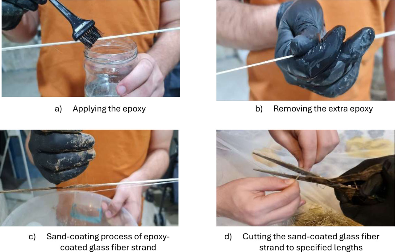
Figure 1:
Preparation of epoxy-coated and sand-coated glass fiber strands
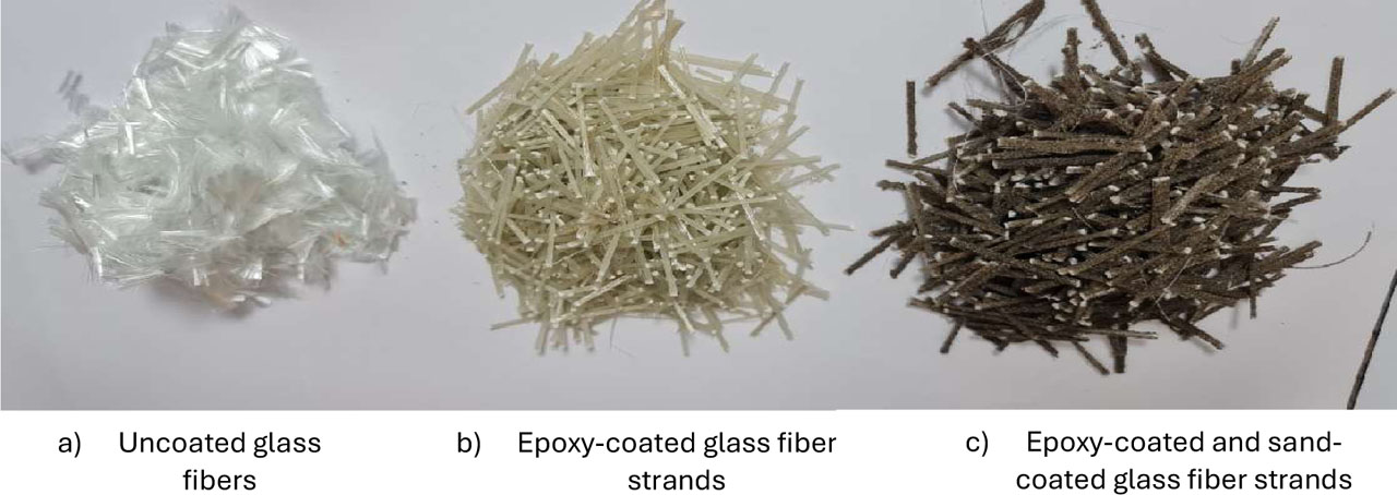
Figure 2:
Types of glass fibers
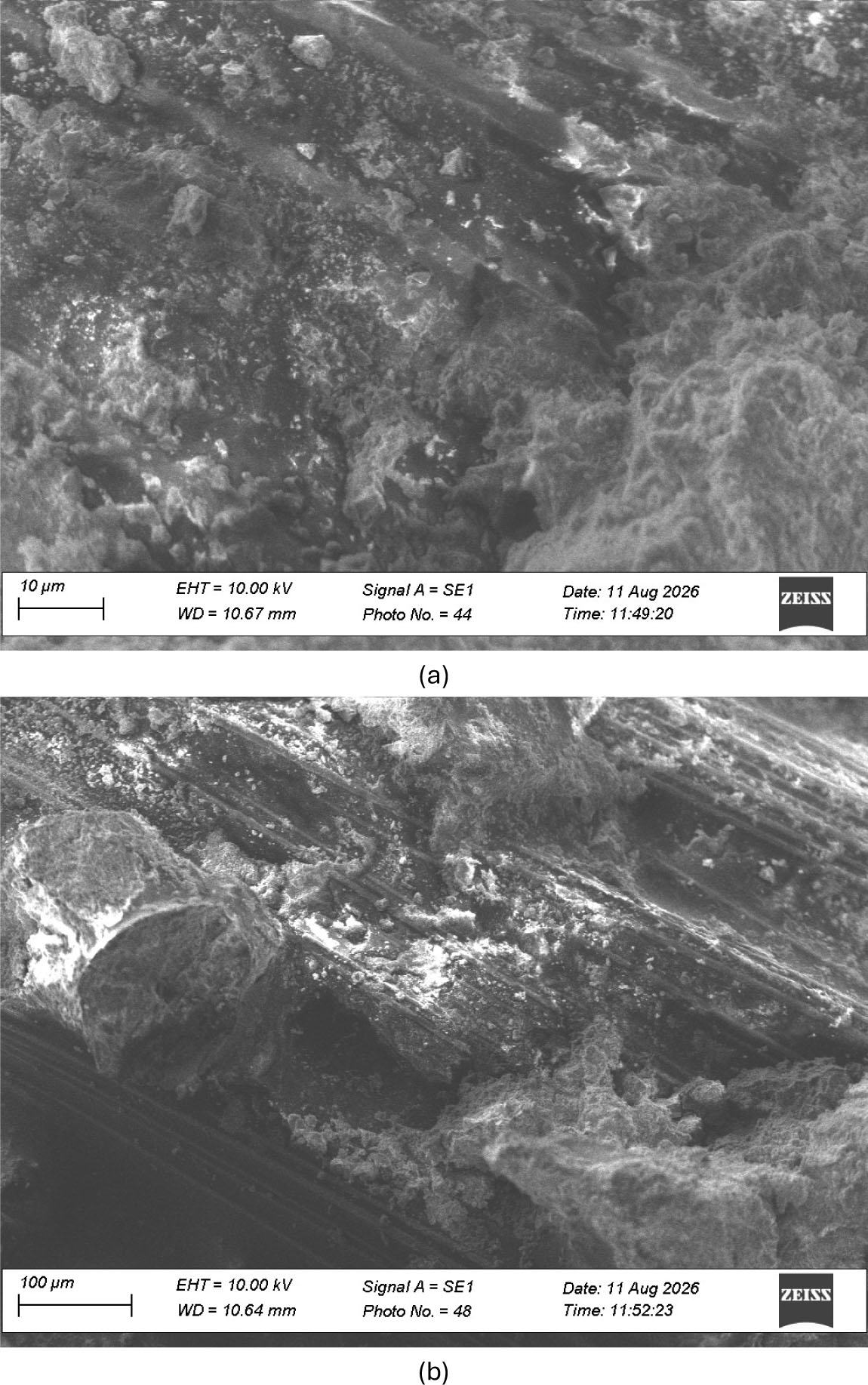
Figure 3:
SEM micrographs of epoxy-coated and sand-coated glass fiber strands surrounded by cement mortar; (a) 10 [μm] scale, (b) 100 [μm] scale
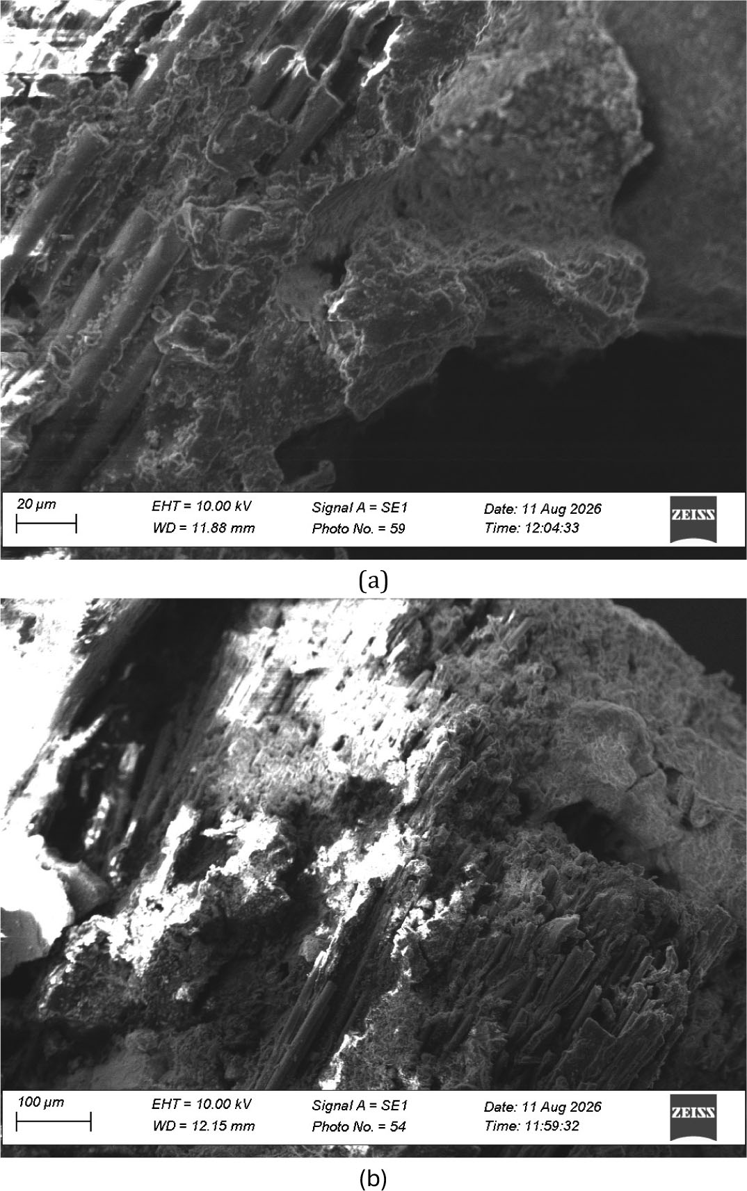
Figure 4:
SEM micrographs of epoxy-coated glass fiber strands surrounded by cement mortar; (a) 20 [μm] scale, (b) 100 [μm] scale
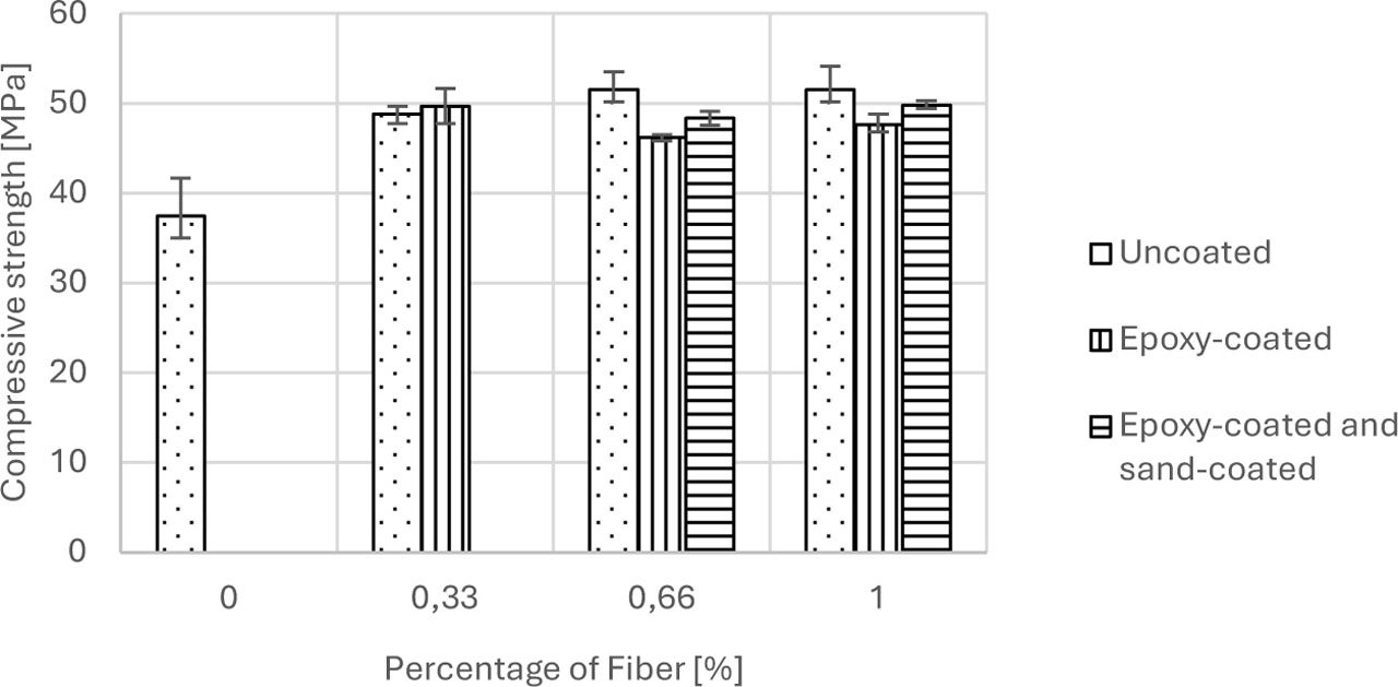
Figure 5:
Compressive strength vs. percentage of glass fibers
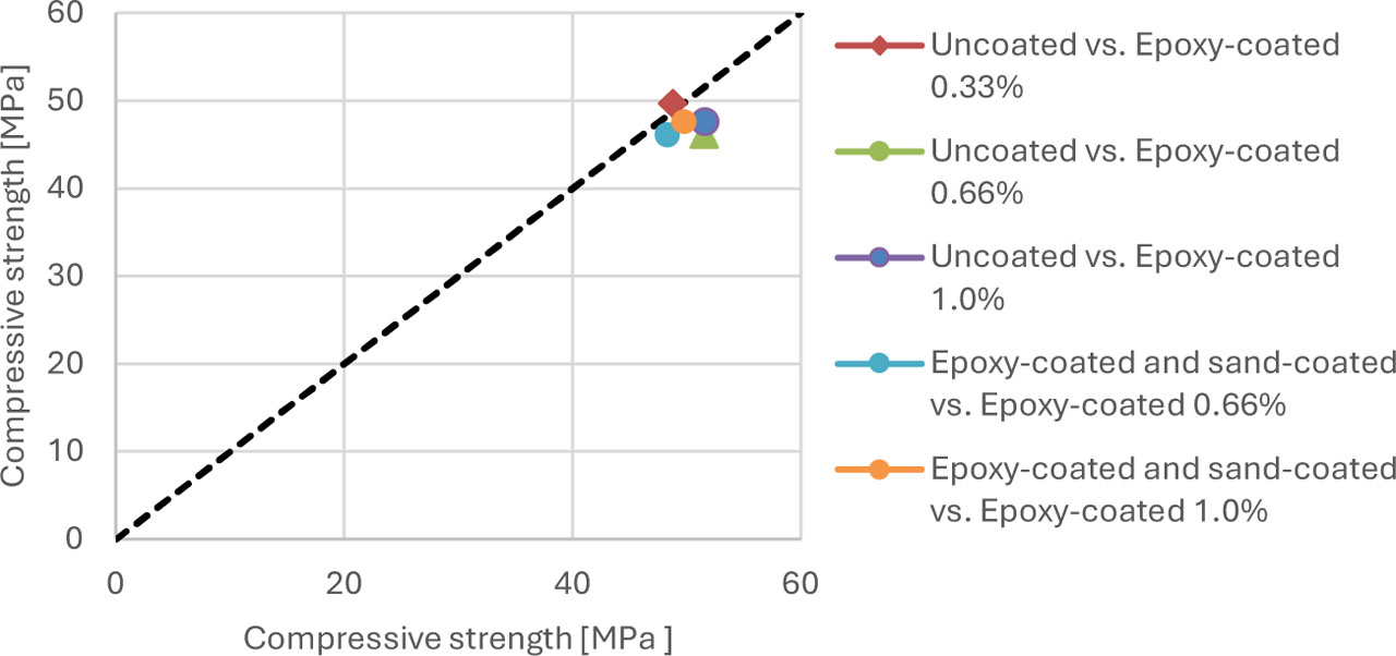
Figure 6:
Comparison of compressive strength of concrete mixtures (x-axis represents the results of uncoated or epoxy-coated and sand-coated; y-axis represents the results of Epoxy-coated)
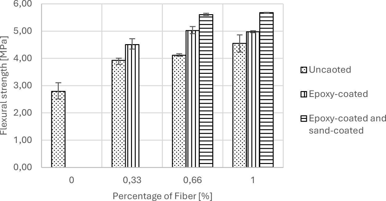
Figure 7:
Flexural strength vs. percentage of glass fibers
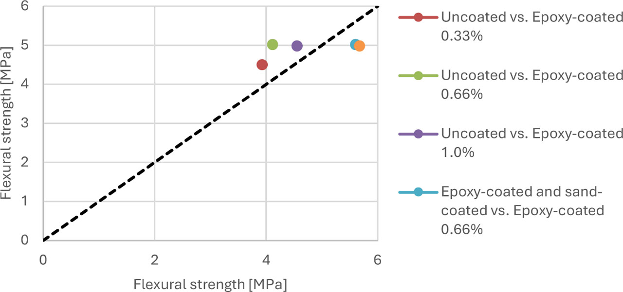
Figure 8:
Comparison of flexural strength of concrete mixtures (x-axis represents the results of uncoated or epoxy-coated and sand-coated; y-axis represents the results of epoxy-coated)
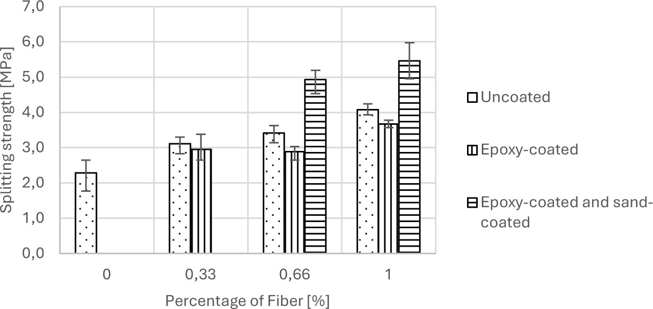
Figure 9:
Splitting strength vs. percentage of glass fibers
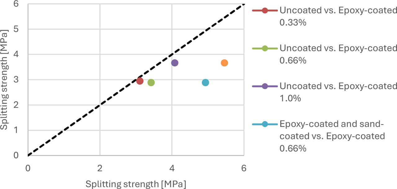
Figure 10:
Comparison of splitting strength of concrete mixtures (x-axis represents the results of uncoated or epoxy-coated and sand-coated; y-axis represents the results of Epoxy-coated)
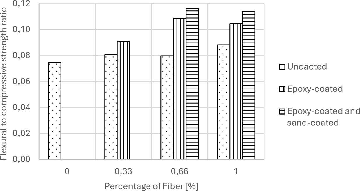
Figure 11:
Flexural to compressive strength ratio
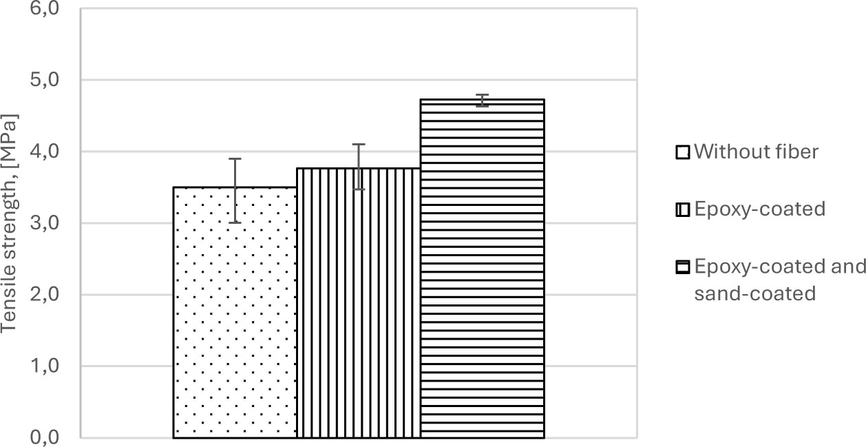
Figure 12:
Tensile strength of cement mortar briquettes
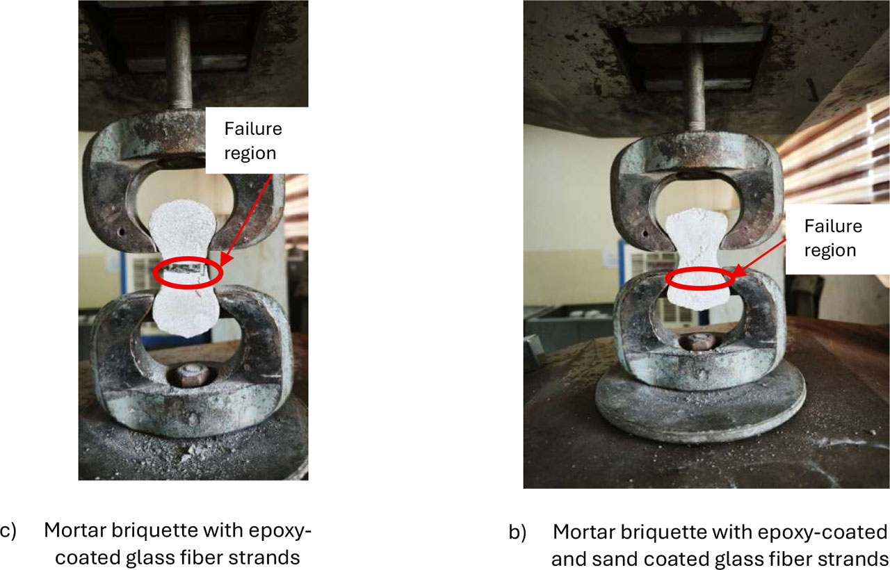
Figure 13:
Direct tensile strength test setup and failure modes of mortar briquette specimens
Table 1:
Chemical composition and specific gravity of ordinary Portland cement
| Component | Portland cement |
|---|---|
| SiO2 [%] | 19.8 |
| Al2O3 [%] | 4.13 |
| Fe2O3 [%] | 3.85 |
| CaO [%] | 61.87 |
| MgO [%] | 3.52 |
| SO3 [%] | 1.79 |
| Cl− [%] | 0.01 |
| LOI [%] | 2.35 |
| Specific Gravity [-] | 3.15 |
Table 2:
Physical properties of ordinary Portland cement
| Property | Value |
|---|---|
| Initial setting time [Minutes] | 125 |
| Final setting time [Minutes] | 300 |
| Blaine [m2/kg] | 300 |
| Expansion [%] | 0.04 |
| 3 days compressive strength [MPa] | 11 |
| 7 days compressive strength [MPa] | 18 |
| 28 days compressive strength [MPa] | 29 |
Table 3:
Properties of Glass fiber
| Glass fiber* | Epoxy-coated glass fiber strand** | |
|---|---|---|
| Tensile stress [MPa] | 1255 | 1129 |
| Elastic modulus [GPa] | 81.3 | --- |
| Strain [%] | 1.87 | --- |
| Density [g/cm3] | 2.8 | --- |
| Diameter [μm] | 18 | ≈ 700 |
Table 4:
Mixture proportions
| Mixtures* | Weight proportion (Cement: Fine agg.: Coarse agg.) | w/c | Cement [kg/m3] | Water [kg/m3] | Fine Aggregate [kg/m3] | Coarse Aggregate [kg/m3] | Super plasticizer [L/m3] |
|---|---|---|---|---|---|---|---|
| MC-0-U | 1:2.75:4 | 0.35 | 308 | 108 | 847 | 1232 | 2.04 |
| MGF-0.33-U | 1:2.75:4 | 0.35 | 308 | 108 | 847 | 1232 | 2.55 |
| MGF-0.66-U | 1:2.75:4 | 0.35 | 308 | 108 | 847 | 1232 | 3.05 |
| MGF-1.0-U | 1:2.75:4 | 0.35 | 308 | 108 | 847 | 1232 | 3.30 |
| MGF-0.33-C | 1:2.75:4 | 0.35 | 308 | 108 | 847 | 1232 | 2.55 |
| MGF-0.66-C | 1:2.75:4 | 0.35 | 308 | 108 | 847 | 1232 | 3.05 |
| MGF-1.0-C | 1:2.75:4 | 0.35 | 308 | 108 | 847 | 1232 | 3.30 |
| MGF-0.66-CS | 1:2.75:4 | 0.35 | 308 | 108 | 847 | 1232 | 3.05 |
| MGF-1.0-CS | 1:2.75:4 | 0.35 | 308 | 108 | 847 | 1232 | 3.30 |
Table 5:
Details of experimental test program and specimen quantities
| Test | Name of the standard test | Size / Details of Specimen | Number of specimens |
|---|---|---|---|
| Slump | ASTM C143 | Fresh concrete matrix | 1 per mixture (9 total) |
| Compressive strength | ASTM C39 | Concrete cylinder with a diameter of 6 in. [152 mm] and height of 12 in. [305 mm] | 3 per mixture (27 total) |
| Splitting strength | ASTM C496 | Concrete cylinder with a diameter of 6 in. [152 mm] and height of 12 in. [305 mm] | 3 per mixture (27 total) |
| Flexural strength | ASTM C78 | Concrete prism with dimensions of 4 in. × 4 in. × 20 in. [100 mm × 100 mm × 500 mm] | 3 per mixture (27 total) |
| The tensile strength of the epoxy-coated glass fiber strands | ASTM D7205-06 | Epoxy-coated glass fiber strand | 3 |
| Tensile strength (cement mortar) | ASTM C190 | Cement mortar briquette, 3 in. [75 mm] long, with a standardized necking cross-section of 1 in. × 1 in. [25 mm × 25 mm] | 3 |
| Tensile strength (cement mortar with 3 epoxy-coated glass fiber strands) * | ASTM C190 | Cement mortar briquette, 3 in. [75 mm] long, with a standardized necking cross-section of 1 in. × 1 in. [25 mm × 25 mm] | 3 |
| Tensile strength (cement mortar with 3 epoxy-coated and sand- coatedglass fiber strands) * | ASTM C190 | Cement mortar briquette, 3 in. [75 mm] long, with a standardized necking cross-section of 1 in. × 1 in. [25 mm × 25 mm] | 3 |
Table 6:
Concrete properties
| Mixtures* | Slump [mm] | Temp., [°C] |
|---|---|---|
| MC-0-U | 130 | 34.5 |
| MGF-0.33-U | 130 | 32.0 |
| MGF-0.66-U | 130 | 31.8 |
| MGF-1.0-U | 110 | 30.8 |
| MGF-0.33-C | 135 | 30.0 |
| MGF-0.66-C | 120 | 34.5 |
| MGF-1.0-C | 100 | 38.1 |
| MGF-0.66-CS | 115 | 30.5 |
| MGF-1.0-CS | 120 | 31.7 |
* Mixture designation: See Table 4
Table 7:
Mechanical properties of concrete [MPa]
| Mixtures* | Compressive strength (28 days) | Splitting strength (28 days) | Flexural strength (28 days) |
|---|---|---|---|
| MC-0-U | 37.4 | 2.3 | 2.8 |
| MGF-0.33-U | 48.8 | 3.1 | 3.9 |
| MGF-0.66-U | 51.6 | 3.4 | 4.1 |
| MGF-1.0-U | 51.6 | 4.1 | 4.6 |
| MGF-0.33-C | 49.7 | 3.0 | 4.5 |
| MGF-0.66-C | 46.2 | 2.9 | 5.0 |
| MGF-1.0-C | 47.6 | 3.7 | 5.0 |
| MGF-0.66-CS | 48.3 | 4.9 | 5.6 |
| MGF-1.0-CS | 49.8 | 5.5 | 5.7 |
* Mixture designation: See Table 4
4. Conclusions
This study evaluated the effects of using uncoated, epoxy-coated, and epoxy-coated and sand-coated glass fiber strands on the mechanical properties and microstructural behavior of concrete mixtures. Based on the experimental results and microstructural analysis, the following conclusions can be drawn:
Microstructural characterization using SEM confirmed that continuous two-part epoxy encapsulation shields inner glass filaments from hydroxyl (OH1) ion ingress and alkaline attack. Sand surface treatment creates surface roughness that allows hydration products (C-S-H gel) to pack tightly around the strands, densifying the interfacial transition zone (ITZ) without interfacial micro-voids.
Surface sand treatment fundamentally alters the fiber-matrix failure mechanism, shifting the failure mode from smooth interfacial pull-out slip to cohesive matrix shear failure in the surrounding concrete.
Incorporating uncoated glass fibers increased the compressive strength by 30.3% to 37.8% compared to the control mixture. However, at higher percentages of 0.66% and 1%, the results showed that the use of epoxy-coated glass fiber strands caused a decrease in the compressive strength (7.6% to 10.5%) compared to mixtures with uncoated glass fibers due to low surface friction of the epoxy-coated strands. Sand treatment restored surface friction, achieving a statistically significant 5.0% compressive strength increase over smooth coated strands.
Concrete mixtures containing epoxy-coated and sand-coated glass fiber strands exhibited superior performance under flexural and splitting tensile loading. At 1.0% volume fraction, specimens with epoxy-coated and sand-coated glass fiber strands achieved maximum flexural and splitting tensile strength increases of 103.5% and 139.0%, respectively, relative to the control mixture.
In direct tension testing, sand-coated strands increased tensile strength by 35.0% and shifted the failure location to the concrete clamping zone. In contrast, smooth epoxy strands produced a statistically insignificant strength increase of 7.4% due to early interfacial slip.
Combining an epoxy coating with a sand surface treatment effectively protects glass fibers from alkaline corrosion while ensuring strong mechanical keying with the concrete matrix, making these strands highly effective for structural concrete applications subject to severe environmental exposure.
Acknowledgements
The study described in this paper was supported by the Construction Materials Laboratory / Civil Engineering Department of the University of Mosul.
Notes
[14] Author Contributions
K.A. conceived and designed the study and contributed to data interpretation and manuscript drafting. A.A. conducted the experiments and collected the data, performed the statistical analysis, and contributed to data interpretation and manuscript drafting. M.J. conducted the experiments and collected the data. All authors critically reviewed and approved the final version of the manuscript and agreed to be accountable for all aspects of the work.