

1. Introduction
The construction industry, historically characterised by the conservative adoption of digital innovations and a low level of automation, is currently undergoing fundamental technological transformation. The advent of Industry 4.0 and the comprehensive digitalization of the sector have introduced radical shifts in the paradigms of structural design and implementation, where Additive Manufacturing (AM) has evolved from a mere rapid prototyping tool into a robust production technology for final structural elements and architectural components, especially concrete ones (Khan et al., 2020; Lu et al., 2019; Hurtig et al., 2025). In this context, AM is frequently identified as 3D construction printing (3DCP), a process based on the automated, layer-by-layer deposition of material governed by a digital model without the requirement for traditional formwork (Ahmed, 2023; Ahmed et al., 2022). This technology directly addresses critical global challenges, including the shortage of qualified labor, the demand for accelerated and affordable construction, and the imperative to reduce material intensity and the overall carbon footprint.
However, the integration of additive technologies also introduces complex research questions regarding the physicochemical phase changes of materials—such as the hydration and hardening of concrete (Wang et al., 2024), sintering of ceramics (Dadkhah et al., 2023), and thermal transition of polymers (Yi et al., 2023)—alongside the challenges of rheological behaviour in fresh mixtures (Lim & Tan, 2024) and intricate thermomechanical processes. Among the various technological modalities, Fused Deposition Modelling (FDM), also known within the open-source community as Fused Filament Fabrication (FFF), is highly prominent. This method relies on the mechanical extrusion of a thermoplastic filament through a heated liquefier or hotend, where the material reaches a viscoelastic state before being deposited onto a substrate to solidify and bond with the previous layers (Ligon et al., 2017). In construction-related tasks, FDM is most utilized for the fabrication of complex molds and formwork using materials such as PLA, PETG, ABS, or TPU.
In addition to extrusion-based methods, photopolymerization techniques like Stereolithography (SLA) and Digital Light Processing (DLP) represent potentially transformative technologies for the industry due to their high resolution and diverse material properties (Ligon et al., 2017). These processes utilize photosensitive resins that undergo radical polymerization and cross-linking – or curing – when exposed to specific wavelengths of light. While SLA employs a precision laser to trace the layer path for a superior surface finish, DLP utilizes a digital projector to irradiate an entire layer simultaneously, making the print speed independent of the surface area, although the resolution remains governed by the pixel size. Furthermore, the industry can leverage Powder Bed Fusion (PBF) for polymers, such as Selective Laser Sintering (SLS) and Multi Jet Fusion (MJF), which are currently employed for the small-scale production of functional plastic components. While SLS uses a laser to locally sinter polymer grains like PA11 or PA12, MJF utilizes a fusing agent and an infrared heat source to coalesce the powder bed (Al Rashid et al. 2021). For high-precision structural applications, Selective Laser Melting (SLM) remains the dominant additive technology for metallic components.
In the contemporary construction landscape, these modern technologies are increasingly promoted to bring value-added solutions, design and individualization to the production and analysis of materials, as illustrated in Figure 1. This contribution specifically focuses on the application of additive technologies in the field of 3D printing with concrete and clay.
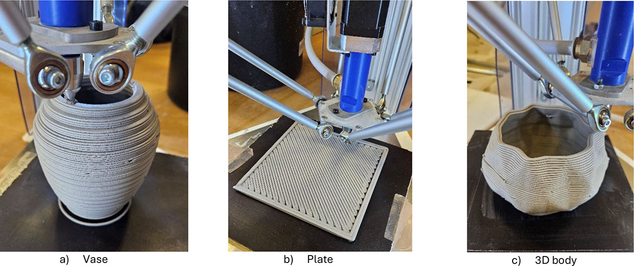
Figure 1:
Design and test print element – clay
This research addresses practical experiences with these processes, not solely for the creation of finished structures, but also to verify equipment parameters, optimize material recipes, and explore operational challenges. The geometry of the test samples was monitored after printing the geopolymer and clay samples, with the broader objective of establishing a standardized manufacturing process integrated with 3D scanning for quality metrology.
Ultimately, 3D printing of clay and concrete enables the realization of geometrically complex objects and topologically optimized shapes that would be unattainable through traditional manufacturing methods. This capability facilitates mass personalization in architecture and design while significantly minimising waste through efficient material distribution. To ensure the structural integrity and geometric fidelity of these printed objects, 3D scanning was employed as a critical post-production control, with a practical demonstration of scanning illustrated in Figure 2.
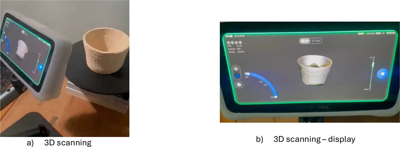
Figure 2:
3D scanning technology – clay
By capturing accurate geometric data using laser or optical sensors, this technology generates precise 3D models and point clouds, allowing for the identification of deviations from the original digital specifications. Owing to its speed and precision, 3D scanning has become a progressive tool for quality assurance and comprehensive documentation of additive manufacturing processes in construction. The 3D scanning option can also be used and extended in reverse engineering, a practical example of which is shown in Figure 3. A thorough understanding of the principles of 3D printing and material behaviour during extrusion, layer deposition, and subsequent hardening can provide essential insights for the advancement of additive manufacturing not only of conventional construction materials (Peknikova et al., 2025), advanced construction materials and technology (Sucharda et al., 2024), but also of alternative material systems (Marcalikova et al., 2024; Hilal et al., 2024; Mohammed et al., 2022). In some cases, 3D polymer systems can be suitably combined with cement composites (Katzer J. et al., 2025).
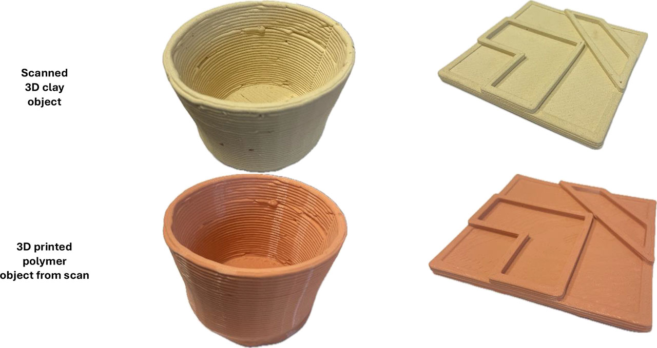
Figure 3:
3D scanning and reverse engineering
The novelty of this study lies in the compact production-to-validation workflow that combines extrusion-based additive manufacturing (for clay and geopolymer blends) with subsequent geometric validation using 3D scanning. In addition to documenting the practical limitations of printing, this study demonstrates how polymer FDM can be used to rapidly prototype functional formwork when direct extrusion is not feasible. Finally, the concept of modular relief tiles is presented as a design-driven application that links manufacturing parameters to repeatable architectural assemblies.
2. Additive Technologies – 3DCP
Additive technologies, publicly known primarily as 3D printing (Ngo et al., 2018), represent a manufacturing approach that fundamentally changes traditional manufacturing processes. Unlike moulding methods, 3D printing is based on the gradual application of layers of material according to a digital model, allowing for a high degree of design freedom, rapid prototyping, and more efficient use of resources (Berman, 2012). This approach also makes it possible to create shapes and structures that would be difficult or impossible to produce using conventional methods, thus meeting the most demanding customer requirements (Shahrubudin et al., 2019).
The main advantages of 3D printing include production flexibility, product customization, reduced waste, and, in the case of some materials, lower energy consumption. However, the limitations of this technique include longer production times for larger objects, the need for specially modified materials, and often higher investment costs for equipment or software (Wang et al., 2017).
A specific area is the 3D printing of materials, such as concrete and clay. Typical 3D printers for polymers, clay, and concrete are shown in Figure 4 (a-c), respectively.
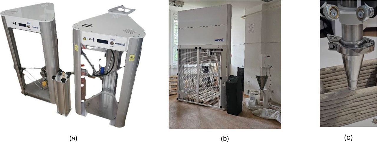
Figure 4:
3D printer: (a) 3D printer Delta construction (left – FDM, right – clay); (b) 3D printer Delta construction – concrete; (c) 3D printer Delta construction – printhead for concrete
The basic division of the design of 3D printers differs mainly according to the kinematics and method of movement of the axes. The Cartesian design is the most common: the X, Y, and Z axes are controlled directly by linear guides or rods, the extruder moves along one axis, and the printing bed is usually along the other or the Z axis is lifted by a screw. The printer is simple to build, service, and calibrate, but at higher speeds, it can suffer from greater inertia and oscillation. The CoreXY uses two motorized belt loops, the combination of which we obtain movement in the XY plane. Therefore, the printer can have a very light extruder, and the system allows for higher acceleration and accuracy with a smaller number of moving masses. The disadvantage is the more complex routing of the belts and fine mechanical calibration. The Delta printer has three vertical towers with a pair of arms on the effector. The positions of the printer arms were combined such that the effector smoothly descended and rose in space. 3D printers with a delta design excel in speed and smoothness of movement due to the low weight of the effector and can print complex curves smoothly, but it has a circular printing surface, more demanding kinematics and accuracy near the edges may decrease.
Concrete appears to be a promising material for the construction industry – from small, prefabricated elements to large structures (Buswell et al., 2018). Its advantages are its availability and good mechanical properties. However, the challenge remains to control the rheological properties of the mixture so that it can be printed while maintaining stability (Le et al., 2012; Ma et al., 2017). Other issues include shrinkage, cracking, and the need for minimal mechanical properties and durability (Al-Qutaifi et al., 2018; Feng et al., 2015; Le et al., 2012).
Clay has different use than concrete – from works of art (Przekop et al., 2025) to highly durable technical clays.
The possibilities of 3D print details and artistic aspects are shown in Figure 5, 6 and 7. Their advantages include precision, aesthetic potential, and exceptional physical properties after firing. Its disadvantages include fragility during the drying phase and the need for precise moisture control before printing (Alonso Madrid et al., 2023).
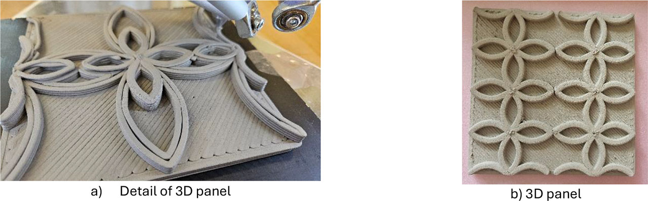
Figure 5:
3D print detail and artistic aspect – clay MA
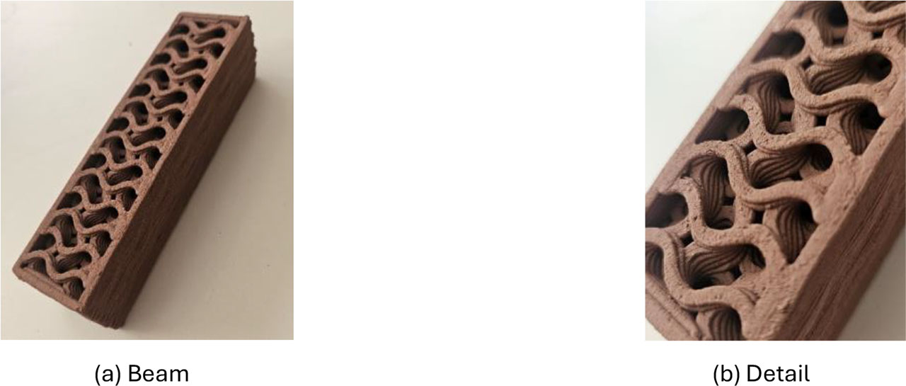
Figure 6:
3D print detail and artistic aspect – clay CERADBUD (1)
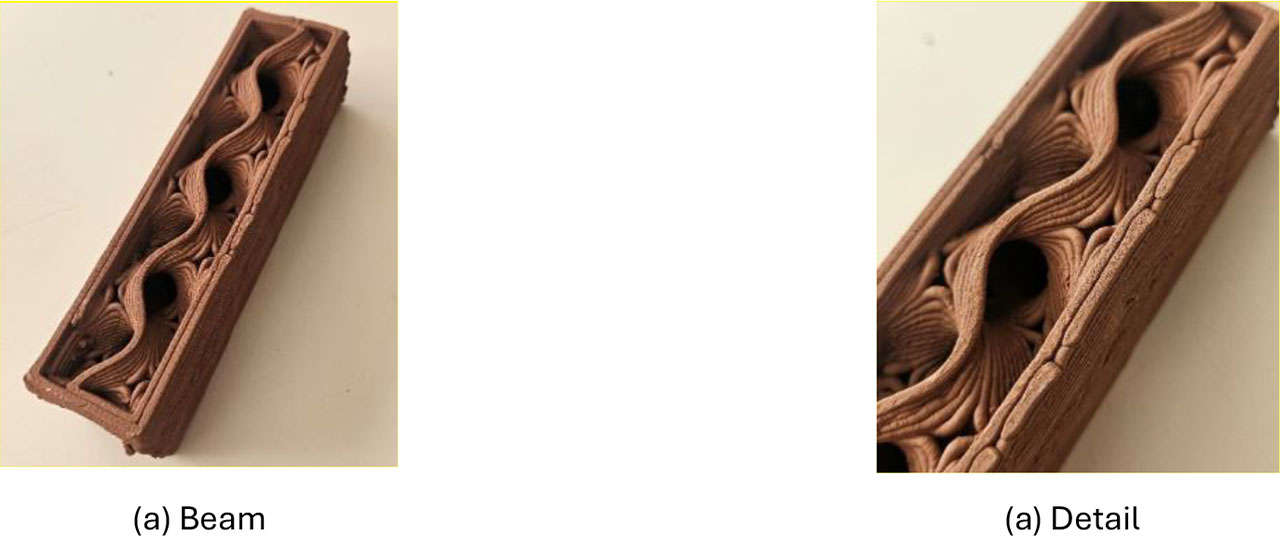
Figure 7:
3D print detail and artistic aspect – clay CERADBUD (2)
These aspects show that 3D printing of concrete and clay is, on the one hand, a promising technology with great application potential, but on the other hand, it is still associated with several open questions. Therefore, this study aimed to present the first practical experiences with printing these materials, identify the main problems when working with them, and suggest directions for further research.
Simultaneously, 3D printing in the construction industry also uses polymer materials. Polymers such as PETG, ABS, or polymer composites, owing to their shaping ability and high strength, are also becoming suitable materials for the additive production of building structures in the form of prototypes or the use of formwork/molds, as shown in Figure 8 and 9.
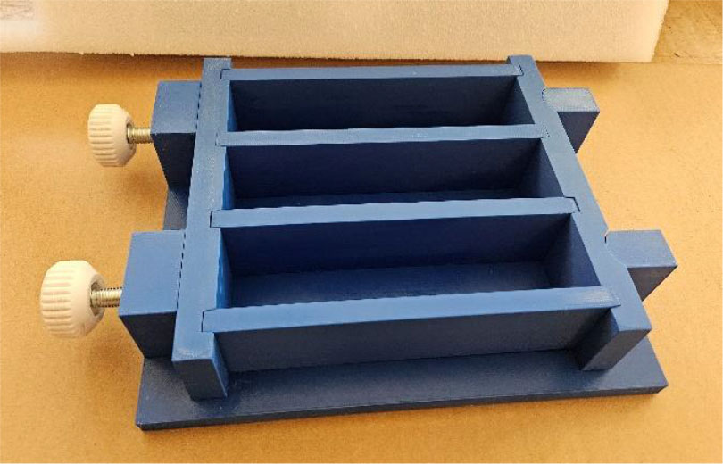
Figure 8:
Mold for concrete samples I
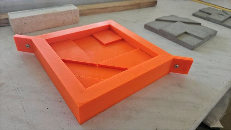
Figure 9:
Mold for concrete samples II
The advantages of polymers include their low weight, resistance to moisture, and possibility of recycling and reuse, which contribute to more environmentally friendly construction. We most often distinguish polymer materials in the form of filament – a printing string that is extruded through a print head, an example is FDM (fused deposition modelling) / FFF (fused filament fabrication) technology. Another option is resin – a liquid material that hardens within the printing layer. An example is the stereolithography (SLA) technology. The third typical option is a fine powder that is sintered using a laser. An example is SLS (selective laser sintering) technology. Other options are also available.
3. Architecture and Research Area
The objective of this study was to verify the technological possibilities of additive technology for advanced applications in design and architectural designs in the construction industry (Sucharda & Dlabikova, 2026), which would not be possible to implement using concrete or clay using conventional methods of production or construction, and to present the potential of polymer materials for moulds within the framework of individualised production with Ordinary Portland Cement (OPC) concrete.
The basic characteristic of the concept architectural design is that it does not matter which of the four sides the tile is turned to. It will always fit onto the next piece because the tiles are the same on all four edges. Each edge of the tile has a lower and middle third and a raised third, forming a continuous relief in all directions at the same time.
In addition to its aesthetic function, relief cladding also has an acoustic function. Because parts of the cladding are raised in relief, these deep and raised parts act as a diffuser of sound waves. Sound waves are reflected from the cladding in various directions, thereby reducing the possibility of sound echoes. However, the acoustic effect presented here is a design-driven expectation rather than a quantitative performance. A straightforward validation can be performed by measuring the room impulse response for a reference flat panel and for the printed relief tile in the same setup, and by comparing standard acoustic descriptors (e.g., reverberation time) and/or frequency-dependent scattering behaviour from a controlled source – receiver arrangement. In this way, it improves the acoustics in the room for the spoken word by placing it on larger flat surfaces such as walls or ceilings, which often cause echoes. The cladding can therefore be used in private interiors such as living rooms, bedrooms, or entrance areas, as well as in public spaces such as reception areas, entrance halls, or even the exterior of buildings.
4. Materials for 3D Printing
The materials selected for 3D printing jobs included geopolymer, a multipurpose material (alternative to traditional OPC concrete) designed to eliminate the risk of cracks even when applied in large thicknesses. It is a composite, natural, mineral matrix, technical plaster/render. It is composed of Pure certified natural lime, Mineral geo-binder, Siliceous washed natural river sand (0.1 – 0.5 mm), Siliceous Washed Natural River Sand (0.1 – 1 mm), Selected Dolomitic Limestone (0 – 1.4 mm), Pure Fine White Carrara Marble, (0 – 0.2 mm). The specifics also include that it is reinforced with TPI 3D technology texture. The control tests for verifying the quality of the printing mixture included granulometry in Figure 10, which was carried out using a laser scattering particle size distribution analyser.
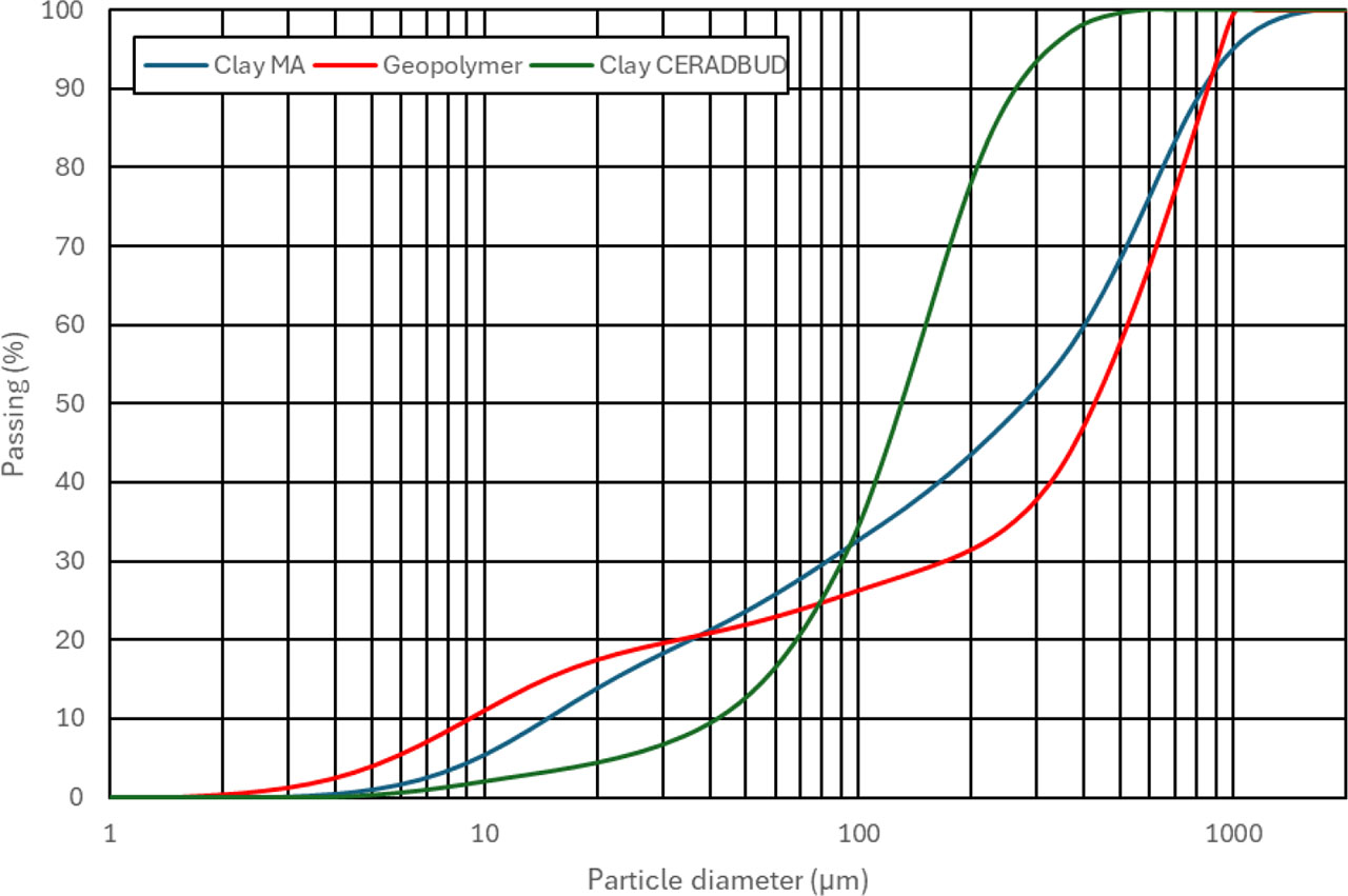
Figure 10:
Granulometry – materials for 3D printing
Considering the volume of the expected printing tasks and the specific architectural and design purposes, including the possibility of producing the material itself, a solution from Geocalce Tenace (Geocalce Tenace, 2025) is used, where, with regard to the specific use for 3D printing, specialised property tests are carried out for a comprehensive description. At the same time, it is also true that the material, in addition to good printing capabilities, has several advantages, including high breathability. Other key properties include pollution-reduced bacteriostatic, carbon dioxide emissions of ≤ 250 g/kg, and recycled regional minerals of ≥ 30 %.
In the case of geopolymer, its static function is not assumed alone but, for example, in combination with Ordinary Portland Cement (OPC) concrete. At the same time, it is also true that to reduce the fragility of the structural and building element, the mixture is reinforced with dispersed fibers, as shown in Figure 11.
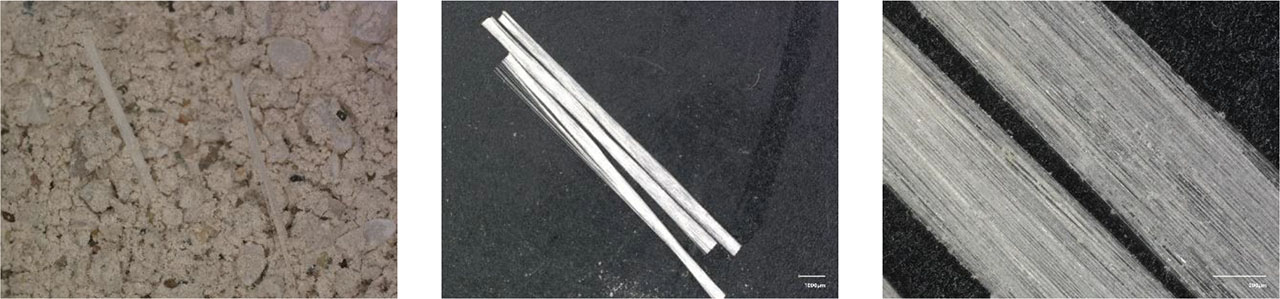
Figure 11:
Detail of fibre of geopolymer: (a) material; (b) fibre; (c) detail of fibre
Another material is clay-type printing material, in which MA materials are mainly used. MA clay material is a smooth Czech-made potter’s clay (Pávek brand), which is light cream after firing. Thanks to its fineness and high plasticity, it is ideal for detailed modelling work, as well as for 3D printing. The firing temperature is in the recommended range of 1180 °C to 1250 °C. As part of a closer characterization, a granulometric analysis in Figure 10 is performed again using a Laser Scattering Particle Size Distribution Analyzer. As part of the delivery of the printing material, the composition was also determined, and the results are summarized in Table 1.
Table 1:
Composition: MA clay material
| Composition | Weight [%] |
|---|---|
| - Na2O | 0.550 |
| - MgO | 0.374 |
| - Al2O3 | 28.613 |
| - SiO2 | 55.658 |
| - P2O5 | 0.066 |
| - SO3 | 0.121 |
| - Cl | 0.031 |
| - K2O | 2.132 |
| - CaO | 0.370 |
| - TiO2 | 1.092 |
| - MnO | 0.010 |
| - Fe2O3 | 1.611 |
| - Loss by annealing | 8.800 |
The second variant of the clay printing material is CERADBUD (Ceradbud, 2025), which is another clay material produced by drying and grinding natural, ecologically clean, red clay, surface-mined from the deposit in Szkucin, without any additives. The chemical composition is summarized in Table 2 and granulometric analysis in Figure 10.
Table 2:
Composition: CERADBUD clay material (Ceradbud, 2025)
| Composition | Weight [%] |
|---|---|
| - SiO2 | 55.00 – 62.14 |
| - Al2O3 | 15.70 – 17.70 |
| - TIO2 | 0.70 – 0.90 |
| - Fe2O3 | 6.09 – 7.90 |
| - MnO | 0.04 – 0.17 |
| - MgO | 2.20 – 3.20 |
| - CaO | 0.33 – 1.81 |
| - Na2O | 0.06 – 0.26 |
| - K2O | 2.90 – 3.50 |
| - P2O5 | 0.05 – 0.18 |
| - Loss by annealing | 7.04 – 13.40 |
In 3D printing, the processability of the printing material is verified in several ways, including a mixture consistency test, a plasticity meter, or the number of layers of the test print. In the present experiments, the test print lasted for up to 45 min.
5. Results and Solutions
The resulting concept (Sucharda & Dlabikova, 2026) of the cladding is shown in Figure 12 and the basic visualization in relief is shown in Figure 13. The main idea of the cladding is to use the potential of 3D printing for direct production – printing or alternatively for the design and creation of molds for concreting.
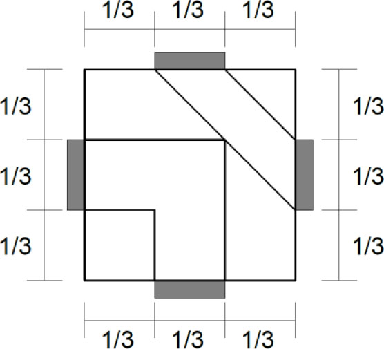
Figure 12:
Cladding concept for building application
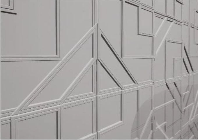
Figure 13:
Cladding concept for building application v visualization
The chosen geometry concept allows the element to be composed in all directions, which makes the work easier and allows for the creation of authentic compositions using this single tile. A comprehensive visualization of the individualized design within the interior is shown in Figure 14.
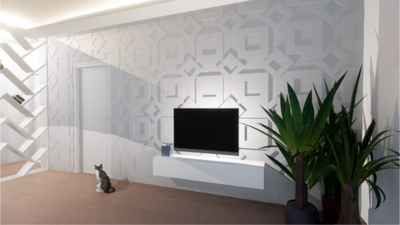
Figure 14:
3D comprehensive visualization
Furthermore, the example in Figure 15 shows a symmetrical composition, where elements are connected regularly, in a repeating sequence. Numerous such compositions can be achieved depending on the size of the area for which the cladding is designed. It creates a rhythmic, symmetrical, repeating tectonic structure that divides the space in the interior, especially in large areas on the walls or even on the ceiling. The lighting settings can then affect the shadows and the overall appearance of the relief, which adds dynamics to the composition. Figure 16 presents an asymmetrical, random composition, where the same motif is not repeated, but the elements connect with each other at random edges. This principle creates an asymmetrical, dynamic, and open composition that can add a dramatic touch to the interior.
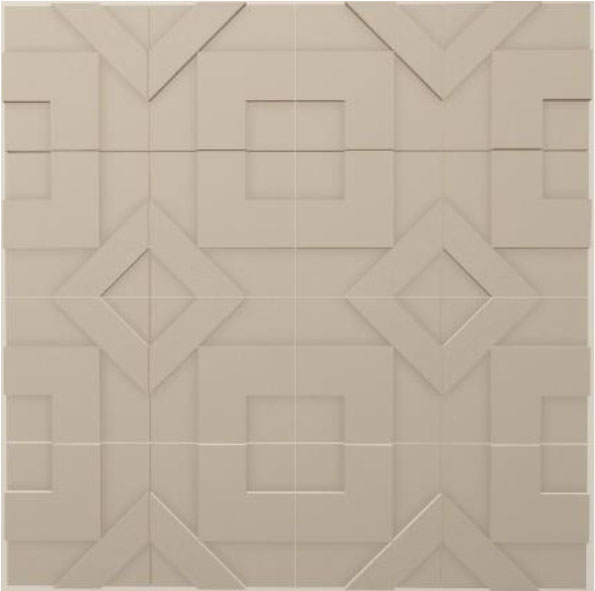
Figure 15:
3D symmetrical composition
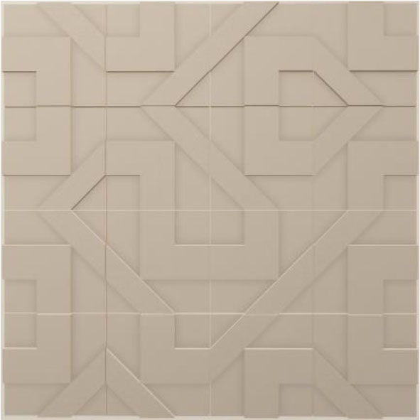
Figure 16:
3D asymmetrical and random composition
5.1. Solutions for FDM
In this case, the solution assumes the use of 3D printing for production of molds for small-scale production of the components. This indirect approach provides a practical pathway for transferring the geometric potential of additive manufacturing into cementitious products, even when the fresh mixture is not suitable for direct nozzle extrusion. The printed polymer mold enables rapid design iterations, repeatable casting, and controlled demolding while maintaining the intended relief geometry and surface continuity of the final product. In this way, FDM-based formwork complements LDM by extending the applicability of the same architectural concept to alternative mixtures (e.g., recycled-content composites) without compromising manufacturability The molds were created based on the architectural and design of the cladding, where PETG polymer material was used for the initial printing of the molds. The mold in Figures 17 and 18 were designed as multi-part and screwable for easier demolding, where the mold consisted of a bottom, which was made up of the relief itself, and two sidewalls, which, when screwed together, tightly clamp the bottom of the mold so that the concrete mixture does not flow around the lower part of the mold during concreting. The screwed joint is designed at the corners of the cladding. The position of the joint was chosen with a view to maintaining the evenness of the surfaces after demolding. The mold itself within the visualization of the model in Figure 19. This solution is suitable in cases where, for example, concrete mixtures with recycled materials are used, which are not directly suitable as printing mixtures.
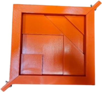
Figure 17:
3D mold for concrete (1)
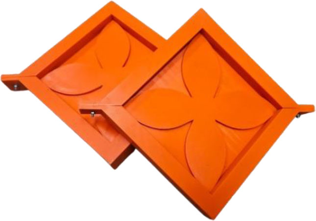
Figure 18:
3D mold for concrete (2)
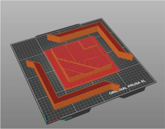
Figure 19:
3D print model
The molds were printed on the Original Prusa XL printer, where the maximum printing area is 36×36 cm with a printing height of 36 cm. Regarding the repeatability of the molds, a 40% grid-type filling was chosen. The choice of filling type and filling density was chosen regarding economic requirements, ensuring functionality and ensuring printing speed. The mold in the Prusa Slicer program can be seen in Figure 19.
5.2. Solutions for LDM – clay
The main part of the 3D printing solution for the ceramic variant was solved using a WASP 2040 Clay 3D printer. The printing was based on a maximum printing area defined by a diameter of 20 cm. The selected printer type uses LDM technology, where the typical material is ceramic or clay. The printer uses a total of 3 nozzle diameters, which are nozzle diameters of 1.5, 2 and 3 mm. In the case of printing the cladding, the nozzle of the largest diameter was used regarding the printing time itself and the shape of the relief itself. In the case of 3D printing of clay (ceramics), it is necessary to ensure the correct consistency of the clay (ceramic) material, which is important for the quality of the print itself. The printing itself can be illustrated in Figure 20 and the resulting printed model in Figure 21.
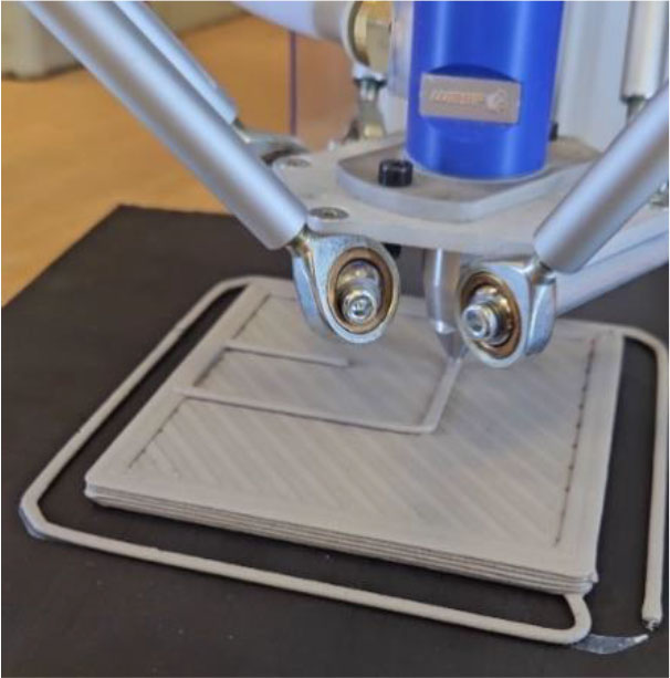
Figure 20:
Clay test sample
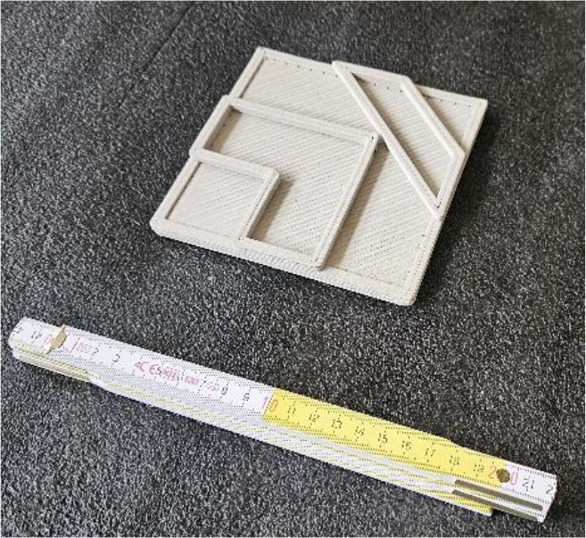
Figure 21:
Clay test sample – print
Printing one tile took approximately 30 minutes. In the case of printing ceramics, it is necessary to dry the tile itself thoroughly at room temperature. The tiles should be dried on a material that can evenly remove moisture from the printed product, otherwise the print will dry unevenly and curl. The tiles should be dried to gradually remove moisture during drying, thus ensuring a flat surface. The results of the 3D printing of tiles are shown in different assemblies for the 3 × 3 variants in Figure 22 and in the 2 × 4 assembly in Figure 23. The print was verified using 3D scanning (Figure 3).
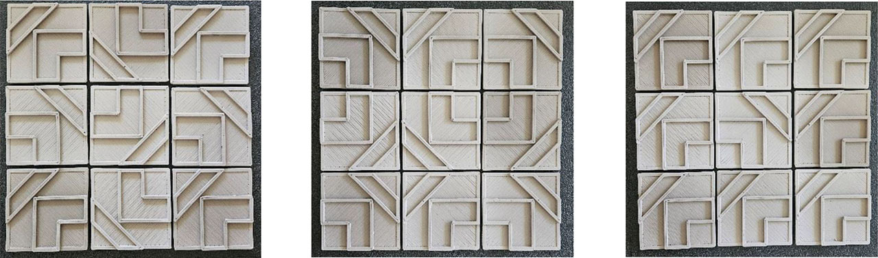
Figure 22:
Clay test samples – 3×3
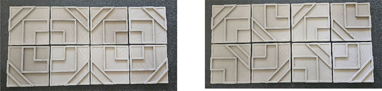
Figure 23:
Clay test samples - 2×4
5.3. Solutions for LDM – geopolymer (Concrete)
The next aim of this study was to practically explore and present the possibilities of 3D printing of concrete materials using a 3D printer delta WASP for concrete. For printing tasks with a larger grain size of printing materials, such as concrete or geopolymer, it is advisable to use a larger type of 3D printer, which also allows for a larger printing space. The delta construction 3D printer used for printing concrete and alternative mixtures is shown in Figure 4. Both 3D printers operate on the principle of LDM (Liquid Deposition Modelling), which allows viscous paste materials to be applied layer by layer. In the case of concrete printing, the print head and transport paths are different. For example, Figure 4c shows the print head during a test print of a multi-layer model. A specific issue in the field of additive technologies is the verification of the proposed values, which include geometry, shape, mechanical properties, and durability. To verify the geometry and shape, 3D scanning can be used, which is illustrated in Figure 24 and 25.
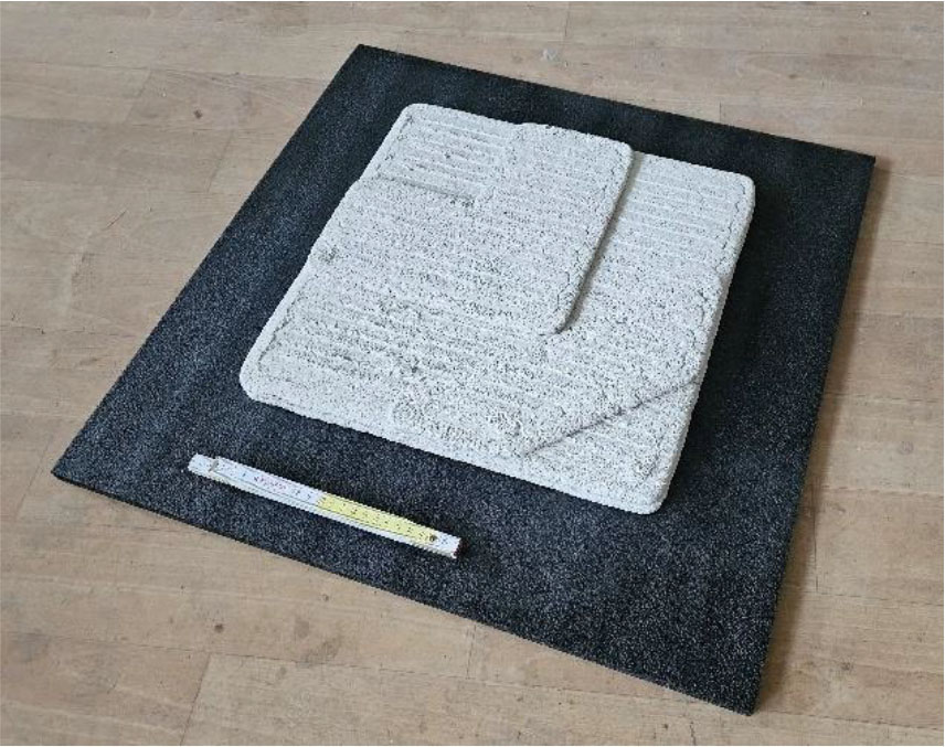
Figure 24:
Geopolymer (concrete) sample
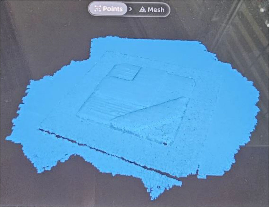
Figure 25:
3D scan – Geopolymer (concrete) sample
In the case of 3D printing and its construction applications, it is necessary to note that the current design code, little practical experience, access to structural analysis and the durability of structures are major barriers, too. Regarding the above, the centre of research and design interest of the research group concentrates on partial structural and building elements, where certification options are broader. In the case of the presented tiles, the use of classic cement-based adhesives is assumed for concrete surface, considering the materials used.
For print elements, their structural strength, geometry, and weight are optimised to meet the intended use. The overall load-bearing capacity within the structure will then be determined primarily by the supporting structure. For geopolymer printing, nozzles with diameters of 16 mm were used, and for clay, they were 3 mm.
5.4. Results for 3D Printing Materials
Laboratory tests of mechanical properties were also performed for the selected printing solutions of ceramics and geopolymer. Specifically, compressive and flexural strength tests were conducted on prismatic specimens with dimensions of 40 mm × 40 mm × 160 mm. For each individual test, three specimens were used, while in the case of compressive strength testing, six specimens were evaluated. All samples were tested at an age of 28 days to ensure the reproducibility of the results. The MA clay was air-dried for one week and subsequently dried in an oven at temperatures of 50, 75, and 105 °C sequentially over a period of three days and finally fired at a temperature of 1200 °C. The statistical evaluation is presented in Table 3. In the case of the geopolymer, the average compressive strength after 28 days was 5.8 MPa and the flexural strength was 1.8 MPa. The corresponding values for ceramics were 13.4 MPa for compressive strength and 4.8 MPa for flexural strength. In both cases, the coefficient of variation did not exceed 20%.
Table 3:
Print materials for LDM (geopolymer and clay)
| Characteristic | Geopolymer | Clay | ||||
|---|---|---|---|---|---|---|
| Volumetric weight [kg/m3] | Flexural strength [MPa] | Compressive strength [MPa] | Volumetric weight [kg/m3] | Flexural strength [MPa] | Compressive strength [MPa] | |
| Mean | 1889 | 1.8 | 5.8 | 1575 | 4.8 | 13.4 |
| Standard deviation | 4.7 | 0.3 | 0.2 | 14.7 | 0.3 | 2.4 |
| Coefficient of variation [%] | 0.2 | 18.3 | 3.3 | 0.9 | 5.6 | 18.1 |
Part of the preparation before the final printing was the verification of the printing mixtures on a test pre-print for geopolymer (concrete) and (clay), where the thickness of the printing mixture and consistency was verified, as shown in Figure 26.
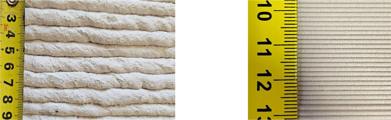
Figure 26:
Printing layers: (a) Geopolymer; (b) Clay
6. Discussion
The research task used additive technologies for the solutions of building and architectural elements, which without the use of 3D printing could be implemented with difficulty or not at all using traditional technologies. Additive technologies themselves are already becoming a practical tool for engineering practice in the field of mechanical engineering and related fields for polymers and metals. In the case of construction, however, 3D printing is a technological challenge and the potential for demanding design tasks is not used. This is because innovative material and technological solutions must be found regarding the requirements of both productions. The above is followed by the task being solved within the research on 3D printing of concrete and clay. Experimental results confirm that additive manufacturing allows the realization of geometrically complex objects, topologically optimized shapes, which cannot be achieved by traditional methods (Mohamed et al., 2025), as illustrated in Figure 27. A key challenge for silicate materials remains the control of the rheological properties of the mixture to ensure stability during printing and to solve problems with shrinkage and cracking. In particular, for clay, precise control of humidity and the drying process have proven to be critical to avoid deformation.
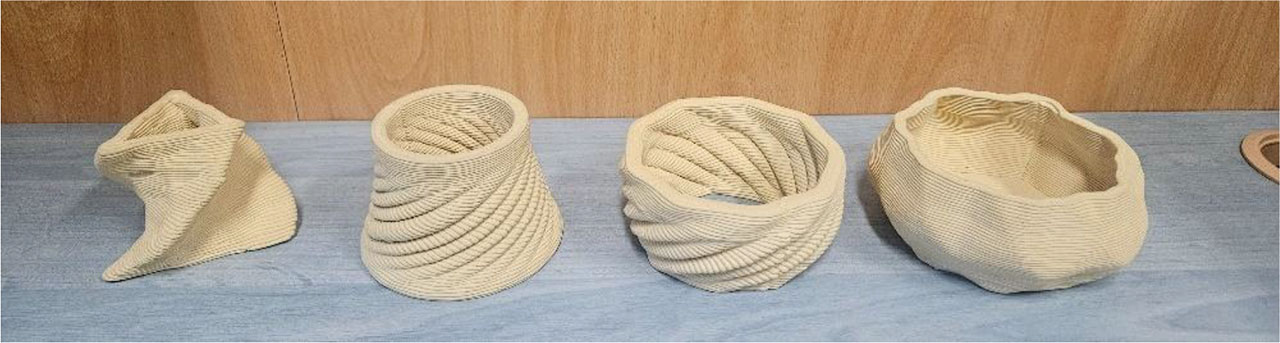
Figure 27:
3D printed clay models
The proposed concept of modular cladding with an asymmetric structure fully exploits the potential of 3D printing for individual design and personalization in architecture. The modularity of the element, which is identical on all four edges, facilitates work and allows the creation of authentic compositions by simply rotating the tiles. In addition to its aesthetic value, the relief structure performs an important acoustic function, with the raised and deep parts acting as sound wave diffusers, thereby reducing echoes both indoors and outdoors. The multifunctionality of the design was verified in the work using two technological approaches: direct printing using LDM technology and indirect mold manufacturing using FDM. The method of printing molds from polymers (e.g. PETG) appears to be highly effective, especially for mixtures with recycled material (Mikula et al., 2020) that are not suitable for direct nozzle printing.
3D scanning has the potential to scan final products and assess their quality and dimensional accuracy. This technology allows for the generation of precise point clouds by scanning and the identification of deviations from the original digital specification, which serves as a critical quality control after production. Scanning combined with reverse engineering provides a progressive way to document and optimize the entire additive manufacturing process in the construction industry, as outlined in (Helle & Lemu, 2021). Overall, despite the persistent limitations of longer production times and special material requirements, 3D printing brings significant efficiency gains, waste reduction, and new creative possibilities to the construction industry.
Among the important aspects of 3D printing and its application in practice is also the possibility of evaluating the speed, efficiency and economy of production. Here, in the context of the presented elements and experiments, it can be stated that 3D printing brings advantages, especially in the area of design freedom for the architect and designer. Often, the structures and details of 3D printing cannot be realized even by convection production and approach. In contrast, in the case of conventional production technology for unified products and elements, the traditional method is more effective. The ambition itself and the possibilities of new structures and surfaces can be illustrated in Figure 5 and 6.
7. Conclusion
Additive technologies and 3D printing in the construction industry provide the potential for new solutions and innovations, which can increase efficiency, consider the sustainability of construction, and offer creativity. Additive technologies enable the faster and more precise production of building components and structures, or. enable finding new solutions with added value and personalized design. The advantages also include the possibility of producing complex shapes and architecturally unique elements that would be traditionally expensive or technically demanding to implement. Potential advantages also include reducing the amount of waste because materials are used exactly as needed and allowing the use of recycled or environmentally friendly raw materials. Additive technologies can shorten the construction process, which improves efficiency, ecological footprint, and design options in the construction industry, thereby contributing to sustainable construction methods.
Acknowledgements
This research was funded by the Jan Amos Komensky Operational Program, financed by the European Union and the state budget of the Czech Republic (grant number CZ.02.01.01/00/22_008/0004631 (Materials and technologies for sustainable development)). This research also received support from the Ministry of Education, specifically from the Student Research Grant Competition of the Technical University of Ostrava under identification number SP2025/084.
Notes
[1] Contributed by Author Contributions
O.S. designed the study and supervised the project. Z.M., R.G., J.K. conducted the experiments. I.D., Z.M. Design and architecture O.S., Z.M., P.C., L.T. performed the data analysis. O.S., Z.M., L.T. contributed to manuscript writing. I.D. Z.M. Visualization. All authors critically reviewed and approved the final version of the manuscript and agreed to be accountable for all aspects of the work.
[2] Disclosure of Interest
The authors declare that they have no known competing financial interests or personal relationships that could have appeared to influence the work reported in this paper.
[3] Data Availability Statement
The data supporting the findings of this study and research are available from available in the https://doi.org/10.5281/zenodo.17095172.