

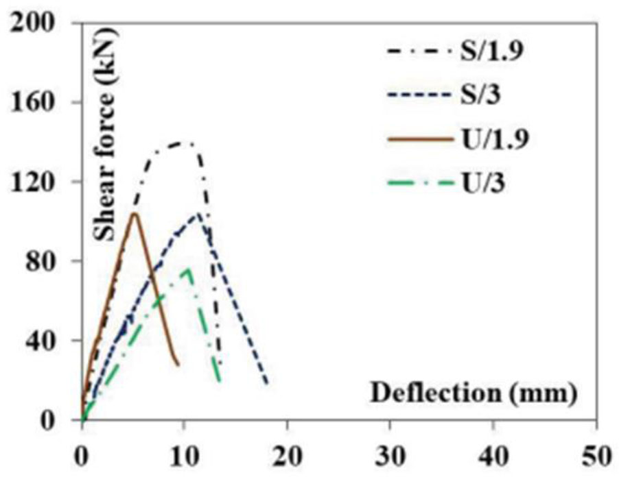
Figure 1:
The effect of the a/d ratio for strengthened and unstrengthened specimens (Sogut et al, 2023)
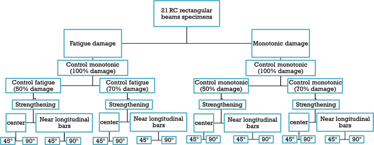
Figure 2:
Flow chart of experimental program
Table 1:
Details of RC beam specimens
| No. of series | Type of loading | Specimen’s codes | Damage ratio [%] | Inclination angle | Location of CFRP bars |
|---|---|---|---|---|---|
| Series 1 | Monotonic | M-100% | Control | - | - |
| M-50% | 50% | - | - | ||
| M-70% | 70% | - | - | ||
| MSC45-50% | 50% | 45° | At the centre | ||
| MSC90-50% | 50% | 90° | At the centre | ||
| MSN45-50% | 50% | 45° | Near longitudinal reinforcement | ||
| MSN90-50% | 50% | 90° | Near longitudinal reinforcement | ||
| MSC45-70% | 70% | 45° | At the centre | ||
| MSC90-70% | 70% | 90° | At the centre | ||
| MSN45-70% | 70% | 45° | Near longitudinal reinforcement | ||
| MSN90-70% | 70% | 90° | Near longitudinal reinforcement | ||
| Series 2 | Repeated | F-50% | 50% | - | |
| F-70% | 70% | - | |||
| FSC45-50% | 50% | 45° | At the centre | ||
| FSC90-50% | 50% | 90° | At the centre | ||
| FSN45-50% | 50% | 45° | Near longitudinal reinforcement | ||
| FSN90-50% | 50% | 90° | Near longitudinal reinforcement | ||
| FSC45-70% | 70% | 45° | At the centre | ||
| FSC90-70% | 70% | 90° | At the centre | ||
| FSN45-70% | 70% | 45° | Near longitudinal reinforcement | ||
| FSN90-70% | 70% | 90° | Near longitudinal reinforcement |
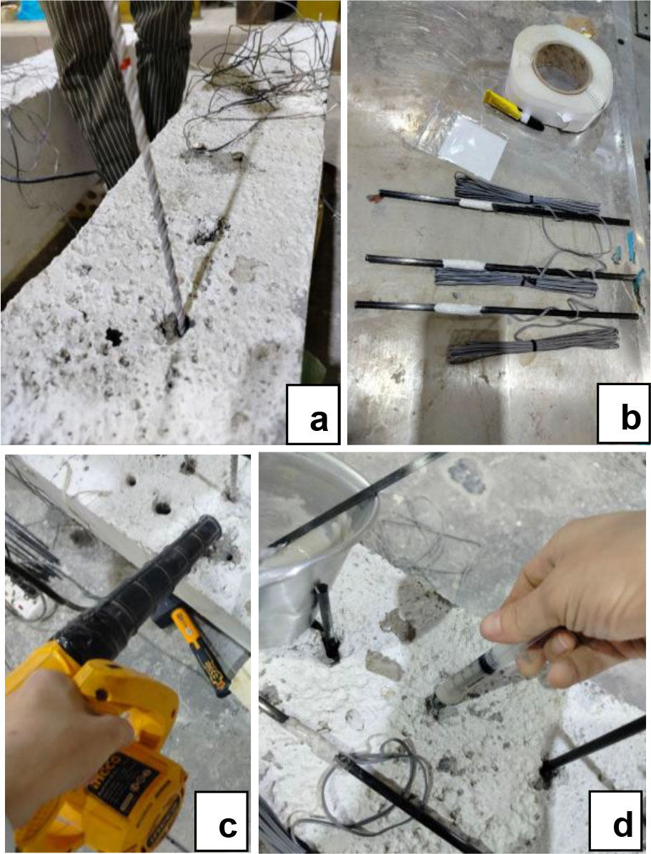
Figure 3:
Strengthening procedure of ETS CFRP bars technique; (a) Preparing holes using a drill, (b) Attaching a strain gauge to CFRP bars, (c) Cleaning the drilled holes by compressed air, (d) injecting the bonding adhesive into the holes and inserting CFRP bars
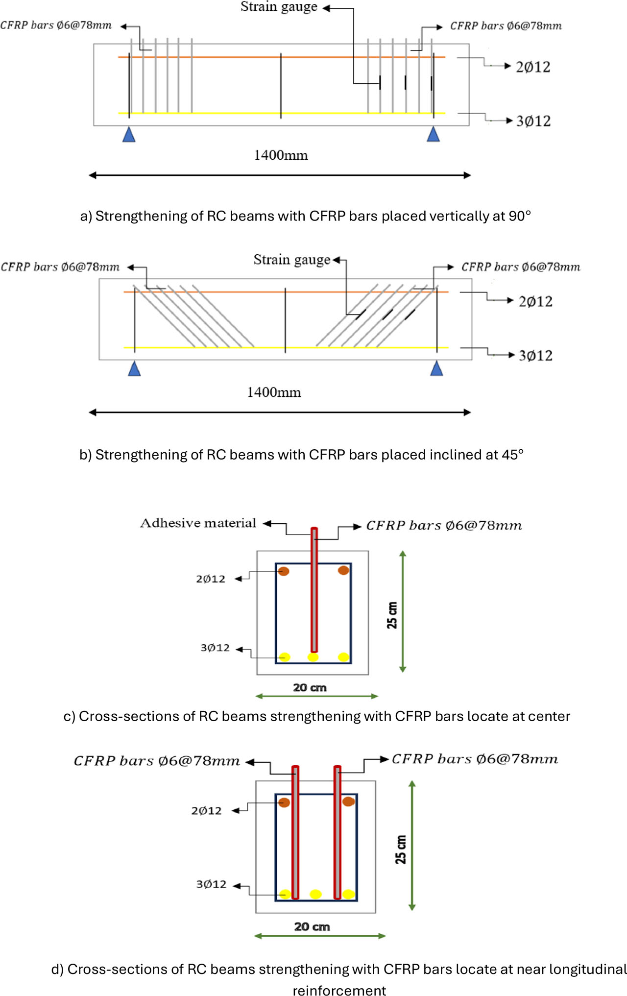
Figure 4:
The design of strengthening an RC beam with CFRP bars
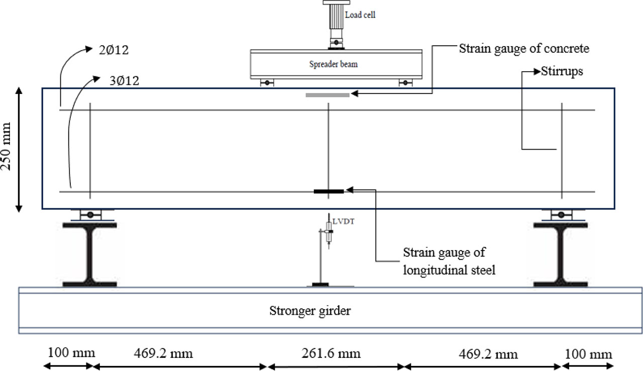
Figure 5:
Test setup and steel reinforcement details of the tested beams
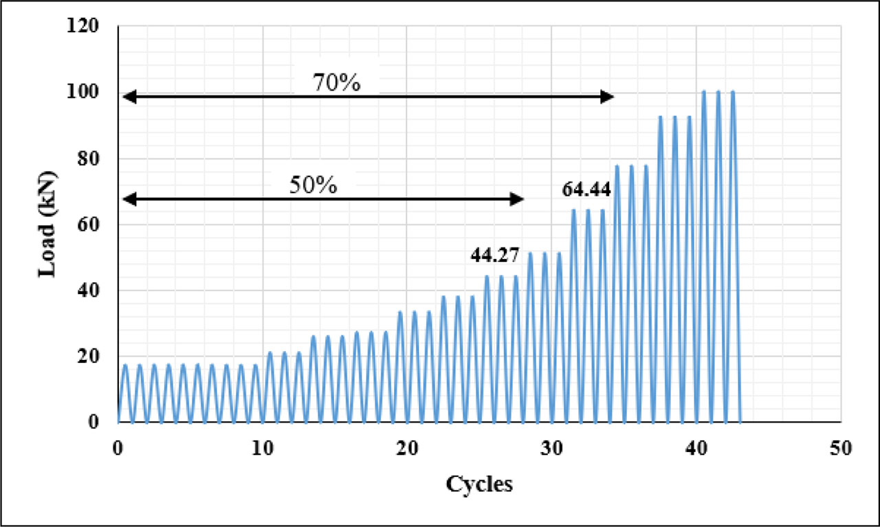
Figure 6:
Load vs. No. of cycles of repeated loading protocol for damaged ratios 50% and 70%
Table 2:
Repeated load protocol
| Stage | No. of cycles | Displacement (mm) | Load (kN) | Cumulative loading cycles | Amplitude |
|---|---|---|---|---|---|
| 0ne | 10 | 0.63 | 17.39 | 10 | 0.1 |
| Two | 3 | 0.76 | 21.29 | 13 | 1.2 |
| Three | 3 | 0.91 | 26.23 | 16 | 1.2 |
| Four | 3 | 1.09 | 27.42 | 19 | 1.2 |
| Five | 3 | 1.31 | 33.41 | 22 | 1.2 |
| Sex | 3 | 1.57 | 38.08 | 25 | 1.2 |
| Seven | 3 | 1.88 | 44.27 | 28 | 1.2 |
| Eight | 3 | 2.26 | 51.24 | 31 | 1.2 |
| Nine | 3 | 2.71 | 64.44 | 34 | 1.2 |
| Ten | 3 | 3.25 | 77.83 | 37 | 1.2 |
| Eleven | 3 | 3.9 | 92.77 | 40 | 1.2 |
| Twelve | 3 | 4.68 | 100.44 | 43 | 1.2 |
Table 3:
Experimental results of tested beams
| Specimen codes | Pu (kN) | Δu (mm) | Δf (mm) | Δ75% (mm) | The efficiency of the ETS (%) | Vmax (kN) | Vf(exp.) (kN) | |
|---|---|---|---|---|---|---|---|---|
| M- Control | 101.43 | 4.6 | 6.34 | 3.06 | - | 50.715 | - | 24.86 |
| M-50% | 88.99 | 4.34 | 5.39 | 3.04 | - | 44.495 | - | 21.95 |
| M-70% | 79.9 | 4.08 | 5.04 | 2.78 | - | 39.95 | - | 21.56 |
| MSC45-50% | 126.87 | 6.34 | 6.95 | 3.36 | 42.57 | 63.435 | 18.94 | 28.32 |
| MSC90-50% | 112.54 | 5.47 | 5.91 | 3.48 | 26.46 | 56.27 | 11.775 | 24.25 |
| MSN45-50% | 130.65 | 6.78 | 7.99 | 3.3 | 46.81 | 65.325 | 20.83 | 29.69 |
| MSN90-50% | 119.23 | 6.34 | 7.56 | 3.42 | 33.98 | 59.615 | 15.12 | 26.15 |
| MSC45-70% | 122.05 | 6.95 | 7.21 | 3.91 | 52.75 | 61.025 | 21.075 | 23.41 |
| MSC90-70% | 112.83 | 6.08 | 6.52 | 3.74 | 41.21 | 56.415 | 16.465 | 22.63 |
| MSN45-70% | 127.1 | 7.47 | 7.9 | 3.82 | 59.07 | 63.55 | 23.6 | 24.95 |
| MSN90-70% | 118.51 | 6.6 | 6.95 | 3.77 | 48.32 | 59.255 | 19.305 | 23.58 |
| F-50% | 82.18 | 4.26 | 5.13 | 3.12 | - | 41.09 | - | 19.75 |
| F-70% | 71.39 | 3.82 | 4.78 | 3.03 | - | 35.695 | - | 17.67 |
| FSC45-50% | 121.42 | 5.21 | 6.17 | 3.97 | 47.74 | 60.71 | 19.62 | 22.94 |
| FSC90-50% | 105.45 | 4.6 | 5.13 | 3.48 | 28.32 | 52.725 | 11.635 | 22.73 |
| FSN45-50% | 127.32 | 5.82 | 6.45 | 3.73 | 54.93 | 63.66 | 22.57 | 25.60 |
| FSN90-50% | 116.24 | 4.95 | 5.73 | 3.74 | 41.45 | 58.12 | 17.03 | 23.31 |
| FSC45-70% | 118.51 | 4.78 | 5.82 | 3.68 | 66 | 59.255 | 23.56 | 24.15 |
| FSC90-70% | 109.99 | 4.78 | 5.47 | 3.91 | 54.07 | 54.995 | 19.3 | 21.1 |
| FSN45-70% | 124.75 | 5.13 | 6.08 | 3.39 | 74.74 | 62.375 | 26.68 | 27.6 |
| FSN90-70% | 113.97 | 4.87 | 5.91 | 3.89 | 59.64 | 56.985 | 21.29 | 22 |
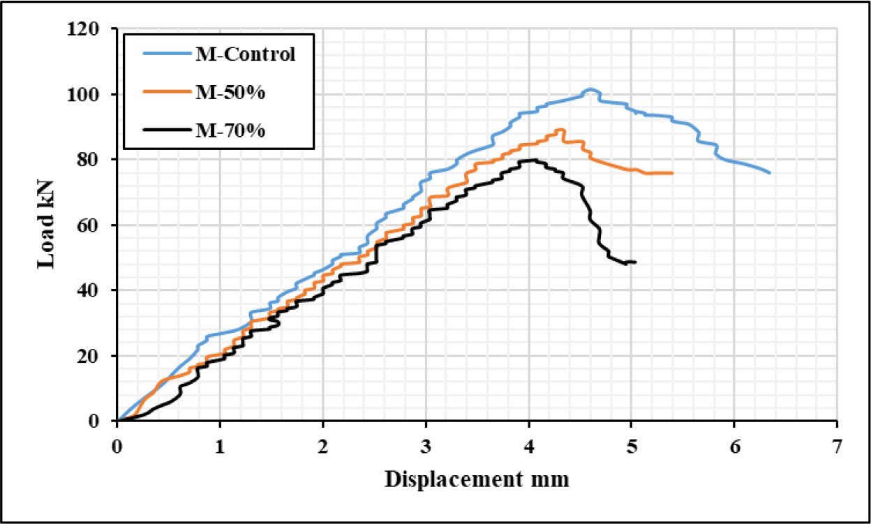
Figure 7:
Load vs. displacement curves for control beam and pre-damaged beam up to 50% and 70%
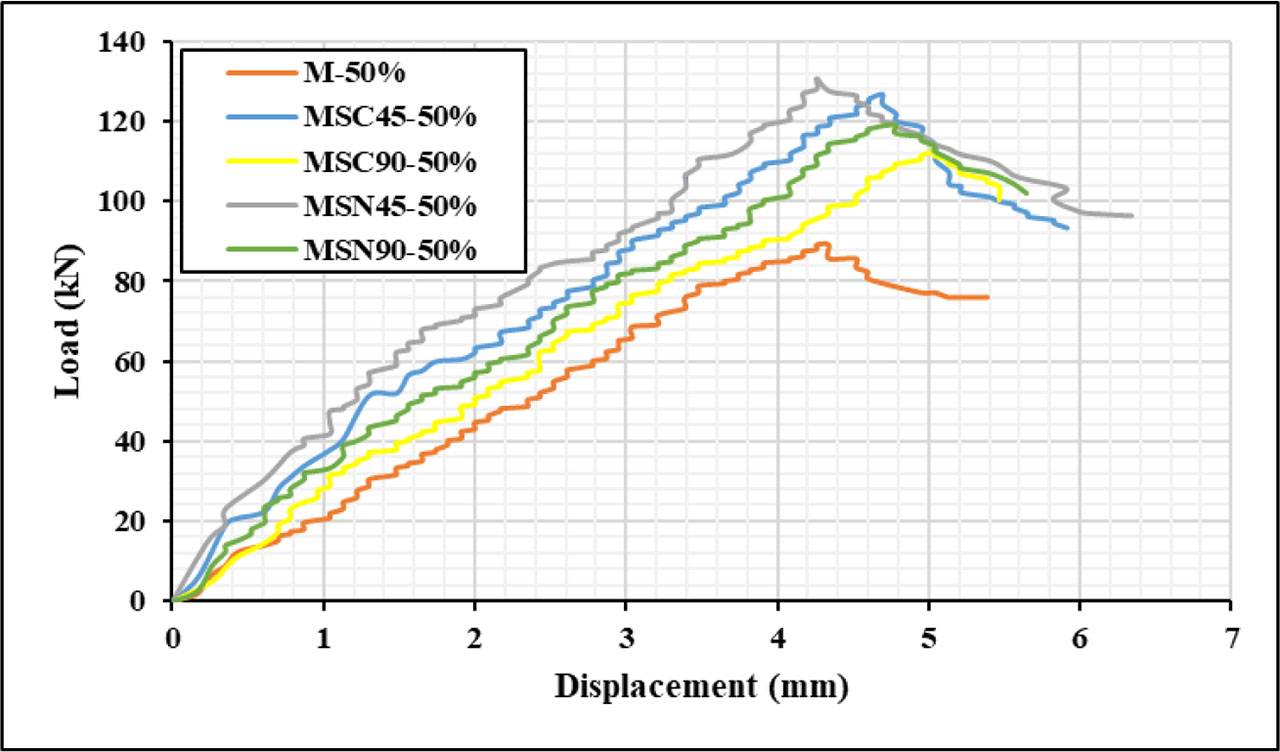
Figure 8:
Load vs. displacement curves for 50% pre-damaged specimens
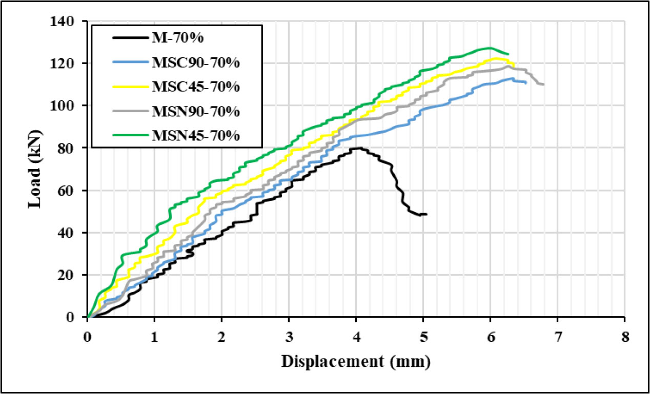
Figure 9:
Load vs. displacement curves for 70% pre-damaged specimens
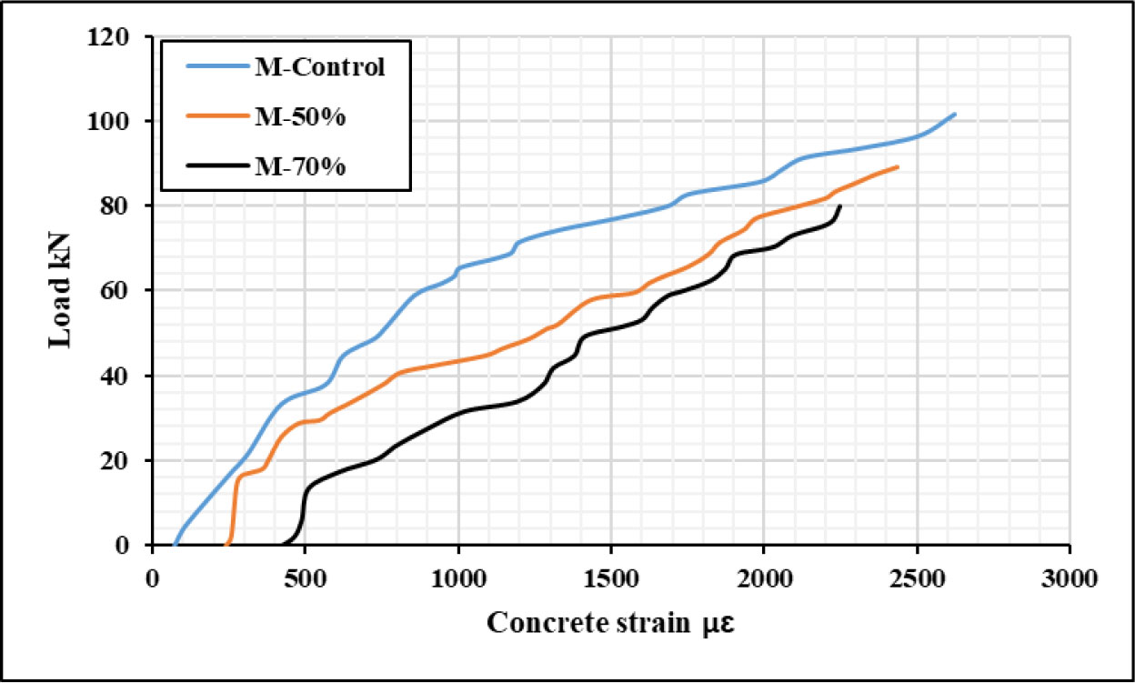
Figure 10:
Load vs. concrete strain of control damaged/undamaged specimens
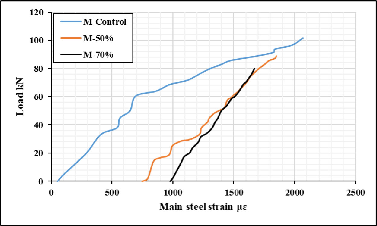
Figure 11:
Load vs. main steel strain of control damaged/undamaged specimens
Table 4:
Total strain of specimens (series 1)
| Specimen code | Concrete strain μɛ | Steel strain μɛ | CFRP strain μɛ |
|---|---|---|---|
| M-50% | 2435 | 1848 | - |
| MSC45-50% | 2631 | 2578 | 1561 |
| MSC90-50% | 2553 | 2513 | 1207 |
| MSN45-50% | 2658 | 2612 | 1653 |
| MSN90-50% | 2582 | 2553 | 1423 |
| M-70% | 2245 | 1669 | - |
| MSC45-70% | 2514 | 2583 | 1315 |
| MSC90-70% | 2408 | 2463 | 1064 |
| MSN45-70% | 2554 | 2634 | 1572 |
| MSN90-70% | 2476 | 2551 | 1209 |
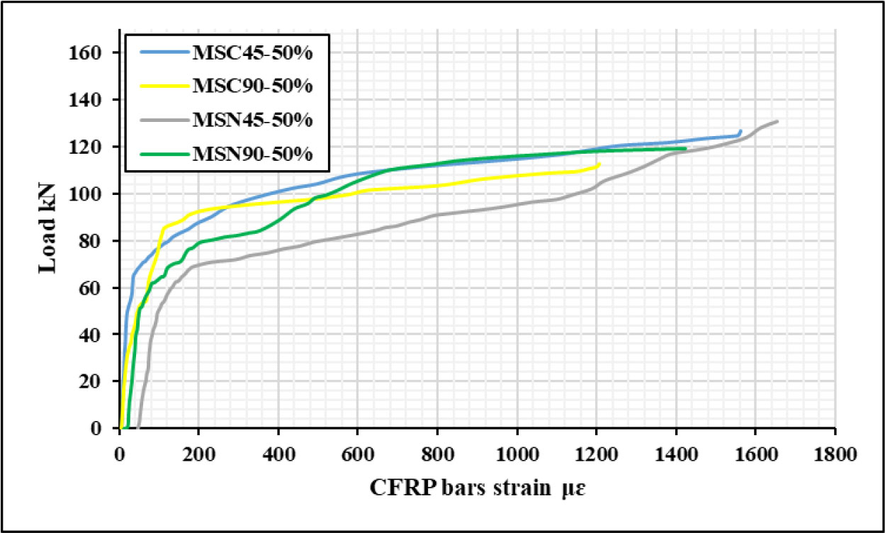
Figure 12:
Load vs. CFRP bars strain of 50% pre-damaged beams
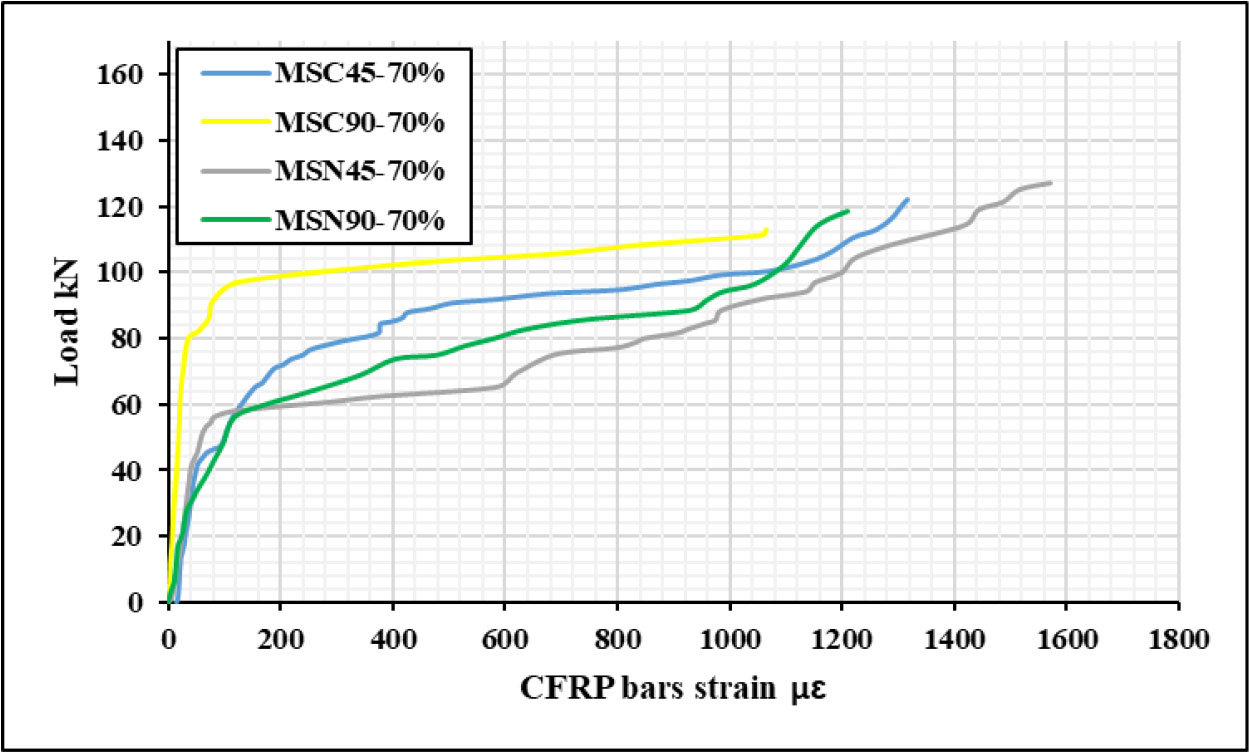
Figure 13:
Load vs. CFRP bars strain of 70% pre-damaged beams
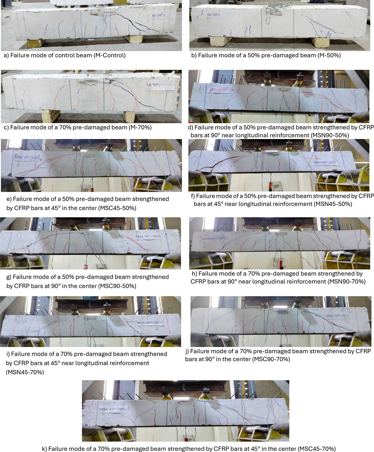
Figure 14:
Failure mode of specimens (Series 1-under monotonic damage)
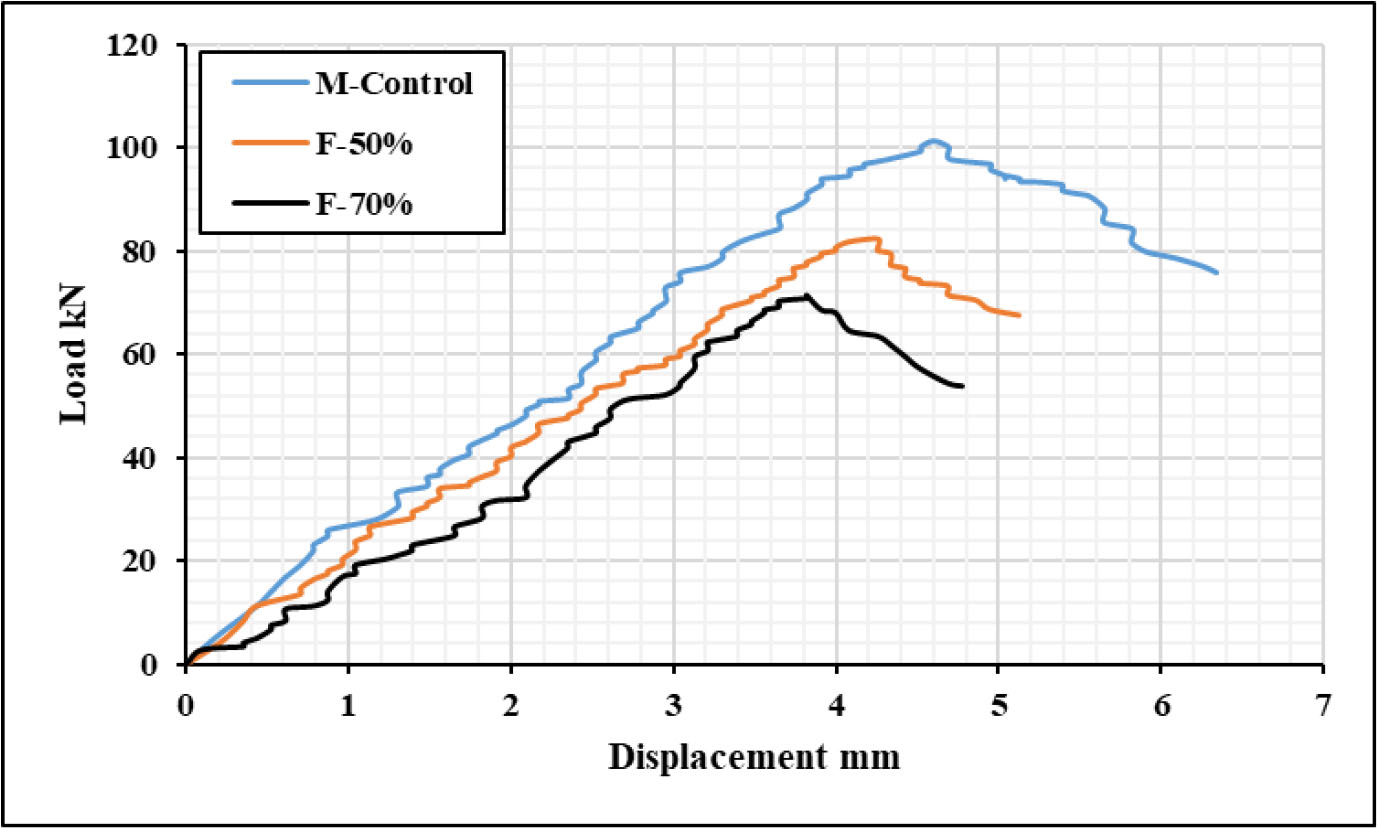
Figure 15:
Load vs. displacement curves for the control beam and pre-damaged repeated loading beam up to 50% and 70%
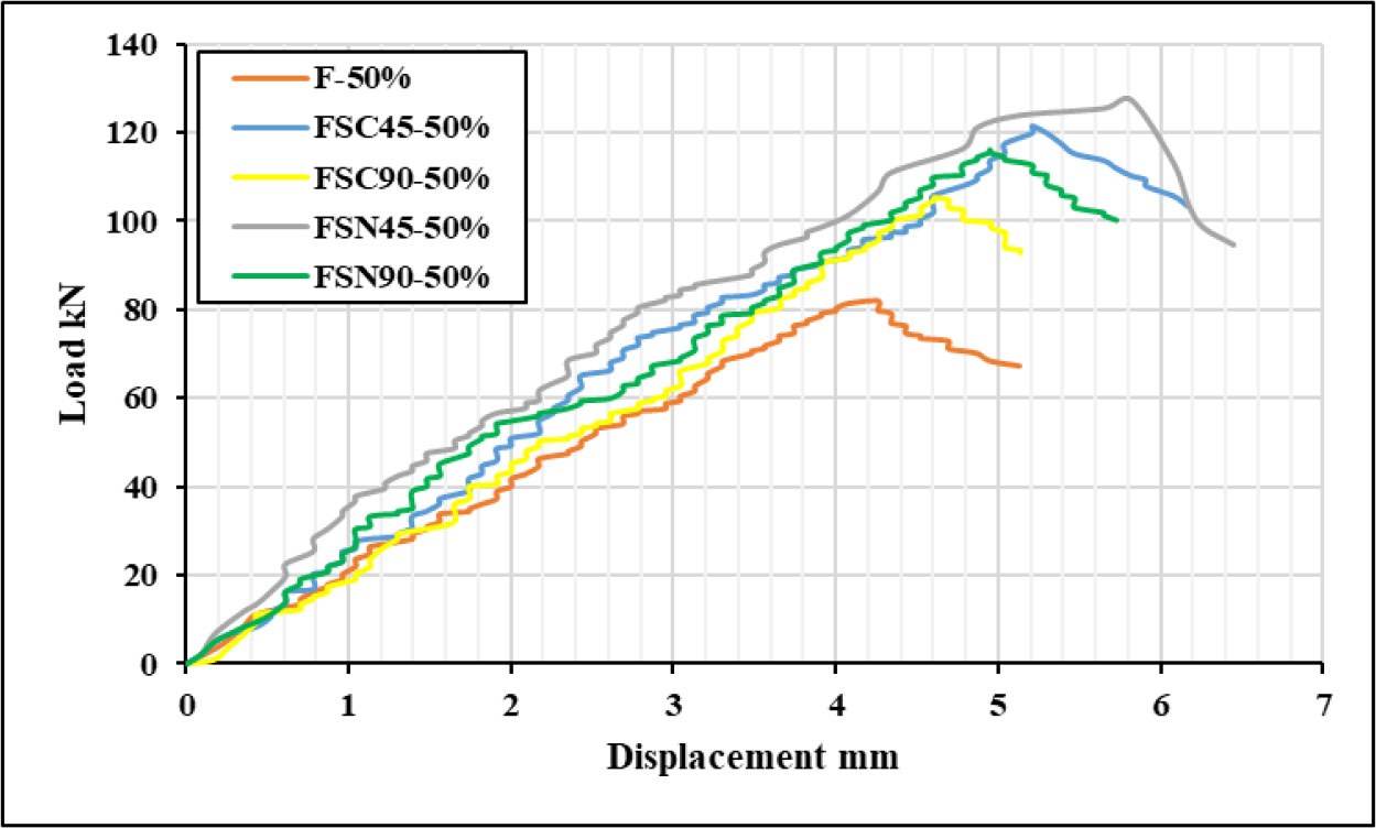
Figure 16:
Load vs. displacement curves for 50% pre-damaged repeated loading specimens
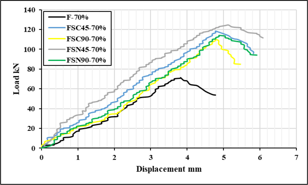
Figure 17:
Load vs. displacement curves for 70% pre-damaged repeated loading specimens
Table 5:
Total strain of specimens (Series 2)
| Specimen code | Concrete strain μɛ | Steel strain μɛ | CFRP bars strain μɛ |
|---|---|---|---|
| F-50% | 2412 | 1823 | - |
| FSC45-50% | 2576 | 2549 | 1543 |
| FSC90-50% | 2517 | 2487 | 1174 |
| FSN45-50% | 2603 | 2586 | 1638 |
| FSN90-50% | 2554 | 2521 | 1408 |
| F-70% | 2221 | 1647 | - |
| FSC45-70% | 2493 | 2568 | 1302 |
| FSC90-70% | 2381 | 2441 | 1042 |
| FSN45-70% | 2531 | 2621 | 1557 |
| FSN90-70% | 2446 | 2534 | 1186 |
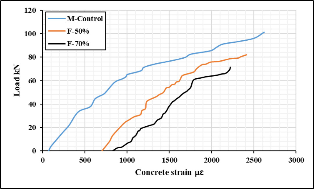
Figure 18:
Load vs concrete strain of control damaged/undamaged specimens
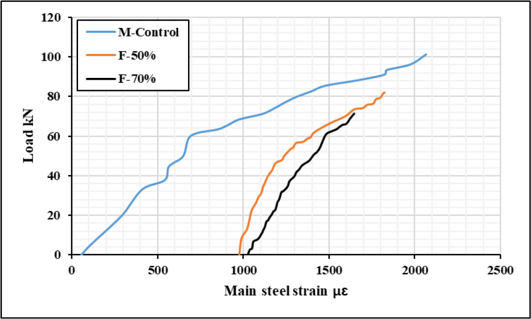
Figure 19:
Load vs main steel strain of control damaged/undamaged specimens
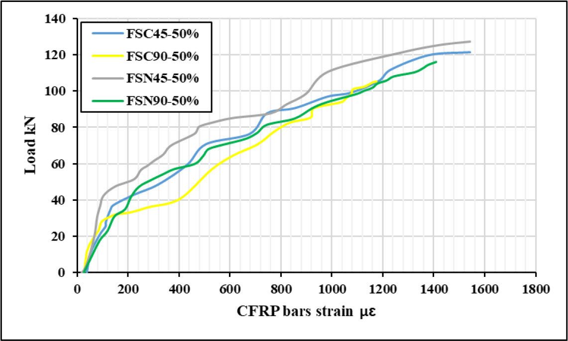
Figure 20:
Load vs. CFRP bars strain of 50% pre-damaged beams
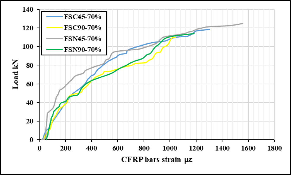
Figure 21:
Load vs. CFRP bars strain of 70% pre-damaged beams
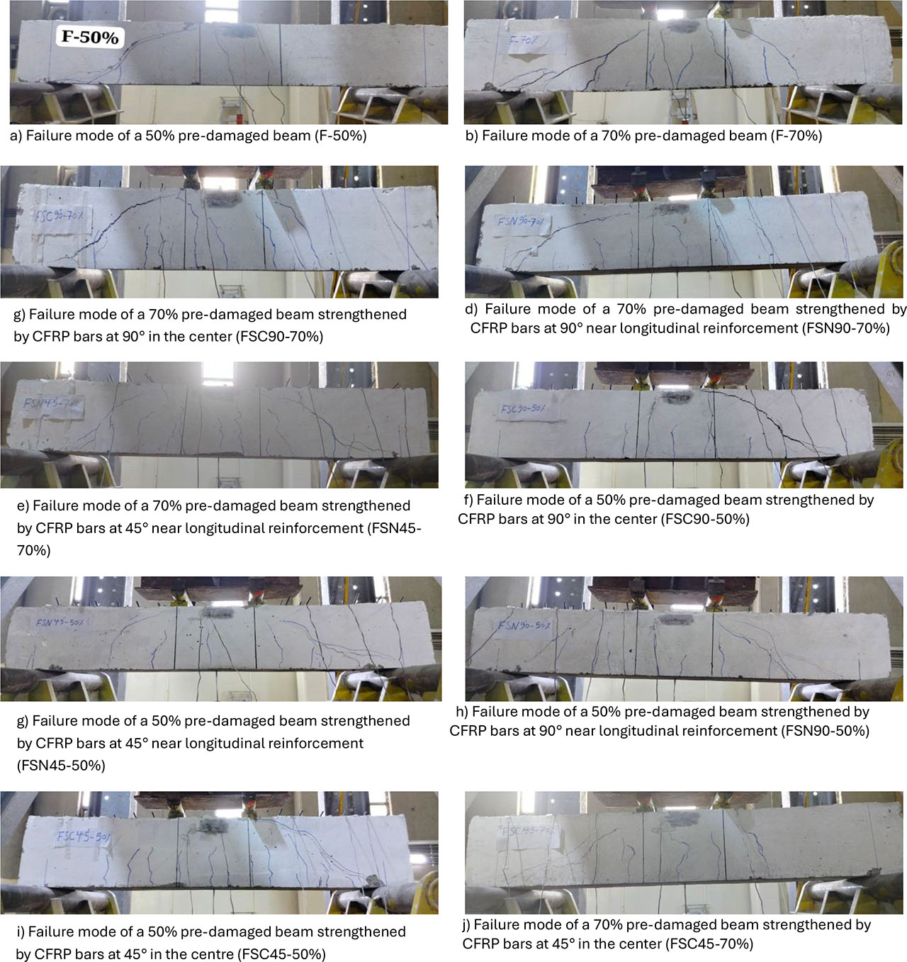
Figure 22:
Failure mode of specimens (Series 2 - under fatigue damage)