

1. Introduction
Reinforced concrete structures face increasing challenges due to rising deterioration rates and higher service loads, and performance demands. In particular, evolving climate conditions accelerate material degradation beyond the levels anticipated in the original design, posing additional threats to structural safety and serviceability (Kopiika, 2024) (Kopiika, 2025). Among these challenges, shear deficiencies are of particular concern, as shear failure is brittle in nature and can occur abruptly without warning, often leading to catastrophic consequences. Increased loading, changes in structural function, design inadequacies, and material degradation can all lead to shear deficiencies in reinforced concrete structures (Lees et al, 2002; Kesse et al, 2007; Dirar et al, 2013). The use of fibre-reinforced polymer (FRP) materials in retrofitting is widely accepted due to their non-corrosive nature, high strength-to-weight ratio, durability, and ease of installation with minimal labour and aesthetic impact, making them ideal for external waterproofing (Breveglieri et al, 2014) (Lateef et al, 2024).
Techniques used to rehabilitate damaged shear areas include Externally Bonded (EB), Near-Surface-Mounted (NSM), and Embedded Through Section (ETS) (Mostofinejad et al, 2013; Charalambidi et al, 2016; Aishwarya et al, 2017). The EB method bonds CFRP sheets to the concrete surface but suffers from issues like fire/vandalism vulnerability, debonding, and the need for surface preparation (Kodur et al, 2006; Pham et al, 2006). NSM embeds CFRP bars or laminates into pre-cut grooves filled with adhesive, offering better bond behaviour and higher flexural and shear capacities (Abdesselam et al, 2023; Hawileh et al, 2022; Alwash et al, 2021; Turki et al, 2023), though cracking and debonding may still occur (Breveglieri et al, 2014). ETS, the most recent technique developed by (Valerio & Ibell, 2003), involves inserting strengthening bars into epoxy-filled holes drilled through the beam’s cross-section. It enhances stress transfer and anchorage due to the confinement provided by concrete, improving shear resistance (Valerio & Ibell, 2003; Moradi et al, 2020). ETS also avoids surface preparation, uses less epoxy, provides better fire and vandalism protection (Valerio & Ibell, 2003; Barros et al, 2013), and allows the use of embedded steel bars, which are corrosion-protected and contribute to truss action within the beam (Raicic et al, 2017).
Based on these advantages, several studies were carried out to assess the ETS technique’s performance in various scenarios. These studies have mostly concentrated on important factors that affect its efficacy, including bar material (Breveglieri et al, 2015) (Valerio et al, 2009), inclination angle (Breveglieri et al, 2015) (Barros JAO & Dalfr, 2013) (Breveglieri et al, 2014), bar spacing (Breveglieri et al, 2015) (Breveglieri et al, 2014), and the existence of internal stirrups (Breveglieri et al, 2015) (Barros JAO & Dalfr, 2013) (Breveglieri et al, 2014). The test results confirmed the effectiveness of the ETS technique in enhancing shear capacity, achieving a 136% increase. The primary failure mode was bar debonding from the surrounding concrete. Maximum strain in FRP bars reached about 0.87% for vertical and 1.00% for inclined installation, attributed to the longer bond length of inclined bars (Breveglieri et al, 2015).
The effectiveness of the ETS technique decreases with higher internal steel stirrup ratios. Tests showed that increasing stirrup size from 2 Ø6 mm to 2 Ø9 mm reduced the shear contribution of ETS-FRP bars by 36.3 kN (vertical) and 8.1 kN (inclined), highlighting that higher transverse steel density can limit the ETS bars’ shear resistance (Breveglieri et al, 2014; Van Hong Bui et al, 2020).
An experimental study was carried out on reinforced concrete beams strengthened in shear using the embedded through-section (ETS) FRP technique, in which the influence of several parameters was investigated, including the presence of internal stirrups as well as the coating, diameter, and spacing of the FRP bars. The findings demonstrated that the ETS technique provides a significant enhancement in shear capacity. Plain-surface and larger-diameter FRP bars exhibited superior strengthening efficiency, whereas the presence of closely spaced internal stirrups led to a reduction in the overall effectiveness of the strengthening system (Mofidi et al, 2012).
Figure 1 presents the effect of the shear span-to-effective depth ratio (a/d) on the shear performance of T-beam specimens strengthened with CFRP ETS bars, compared with unstrengthened specimens. The results indicated that increasing the a/d ratio from 1.9 to 3.0 resulted in a reduction in shear strength of approximately 27% for control specimens and 23% for strengthened specimens. Conversely, decreasing the a/d ratio from 3.0 to 1.9 led to a corresponding reduction in shear strength from 37.2% to 29.6%. A comparative illustration of the responses of strengthened (S) and unstrengthened (U) specimens at a/d ratios of 1.9 and 3.0 is provided by (Sogut et al, 2023).
Another study on large-scale reinforced concrete beams to evaluate the effectiveness of the embedded through-section (ETS) strengthening technique, considering two crucial variables: the ETS bars’ material (ribbed steel vs. sand-coated CFRP) and their inclination angle (90° and 45°). Compared with unstrengthened specimens, the strengthened beams exhibited substantial enhancements in shear capacity, achieving increases of 47%, 58%, and 59% for steel bars at 90°, CFRP bars at 90°, and CFRP bars at 45°, respectively. These results confirm the high efficiency of the ETS technique and highlight the significant influence of both the strengthening material and bar inclination on shear performance (Adriana et al, 2025).
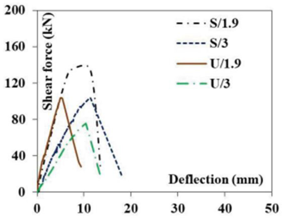
Figure 1:
The effect of the a/d ratio for strengthened and unstrengthened specimens (Sogut et al, 2023)
Studies demonstrating the effectiveness of this technique under cyclic loading are very limited. Just one experimental study was found by (Van Hong Bui et al, 2024), who investigated the effect of several variables, namely the type of reinforcing bars (CFRP/GFRP), the number of stirrups, and the size of the bars on the shear strength of ETS-strengthened concrete beams subjected to cyclic loadings that included medium-cycle fatigue (MCF) and high-cycle fatigue (HCF). The results revealed that, in comparison to unstrengthened beams and beams retrofitted with carbon FRP bars, the fatigue life of ETS-strengthened beams was significantly increased with glass FRP bars with minimal spacing. On the other hand, an excess of stirrups decreased the ETS-FRP strengthening contribution. And as the bar diameter and FRP elastic modulus increased, the strength of the retrofitted beams correspondingly increased.
The influence of the location of ETS bars within the beam cross-section was studied by investigating their placement either near the longitudinal reinforcement or at the centre of the beam section. The results demonstrated that the location of the ETS CFRP bars near the longitudinal significantly improves the efficiency of the strengthening system, through its effect on shear resistance and better stress distribution within the beam. (Tuma et al, 2020). Also, the effect of CFRP bar location, considering placement either at the centre of the beam cross-section or near the longitudinal reinforcement in conjunction with two inclination angles (90° and 45°) was studies by (Naqee et al, 2025) and the results showed a significant improvement in shear capacity and improved crack control when the bars were placed at 45° And near the longitudinal reinforcement, in addition, the finite element model in ABAQUS was also used to validate the experimental results, demonstrating the impact of bar placement on stress distribution and overall strengthening efficacy.
In addition, CFRP tapes have been reported by (Kopiika et al, 2024) as an effective method for restoring the bearing capacity of RC beams with damaged reinforcement. Experimental results demonstrated significant recovery of load-bearing capacity and improved structural performance. However, unlike the ETS technique, CFRP tapes rely on external bonding and are more susceptible to issues such as debonding and limited anchorage, which can reduce their effectiveness in certain applications. This highlights the complementary role of CFRP tapes while reinforcing the advantages of ETS for through-section strengthening.
Despite extensive research on the ETS technique, most studies have focused on parameters like bar material, angle, and spacing under monotonic loading, with limited investigation into cyclic loading, CFRP bar location, and pre-existing damage. Thus, further research is needed to better understand this method. This paper presents an experimental study on ETS-CFRP shear strengthening of damaged RC beams under monotonic and repeated loads, examining key variables: bar angle (90° vs. 45°), damage ratio (50% vs. 70%), and bar location (centre vs. near longitudinal reinforcement), aiming to fill existing research gaps.
2. Experimental Program
2.1. Details of RC Beam Specimens
The twenty-one reinforced concrete beams were designed to fail in shear according to (ACI 318-19, 2019) code, with dimensions (1400 mm length, 200 mm width, and 250 mm height), with lower longitudinal steel bars (3∅12) and upper longitudinal steel bars (2∅12) were used to resist bending without shear reinforcement. The flowchart of the experimental program is shown in Figure 2. These represent two series of rectangular RC specimens that were divided according to the applied load. The first series includes eleven specimens tested under a monotonic load (M), and the second series includes ten reinforced concrete specimens tested under a repeated load to represent fatigue damage (F) with damage ratios of 50% and 70% of the ultimate load of the control specimen, as detailed in Table 1. The RC beams were cast using concrete with an average characteristic compressive strength of 30 MPa and tensile strength of 2 MPa. The top and bottom reinforcement bars were made of high-tensile steel with a modulus of elasticity of 200,000 MPa, a yield strength of 420 MPa, and an ultimate tensile strength of 620 MPa. Carbon fibre reinforced polymer (CFRP) bars of 6 mm diameter, 2800 MPa tensile strength, and 155 GPa modulus of elasticity were used as strengthening elements, bonded with SikaDur®-330 adhesive, which has a modulus of elasticity of 4500 MPa and a tensile strength of 30 MPa.
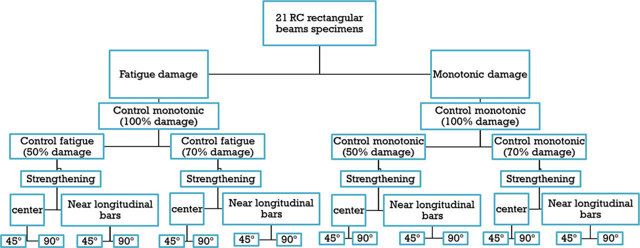
Figure 2:
Flow chart of experimental program
Table 1:
Details of RC beam specimens
| No. of series | Type of loading | Specimen’s codes | Damage ratio [%] | Inclination angle | Location of CFRP bars |
|---|---|---|---|---|---|
| Series 1 | Monotonic | M-100% | Control | - | - |
| M-50% | 50% | - | - | ||
| M-70% | 70% | - | - | ||
| MSC45-50% | 50% | 45° | At the centre | ||
| MSC90-50% | 50% | 90° | At the centre | ||
| MSN45-50% | 50% | 45° | Near longitudinal reinforcement | ||
| MSN90-50% | 50% | 90° | Near longitudinal reinforcement | ||
| MSC45-70% | 70% | 45° | At the centre | ||
| MSC90-70% | 70% | 90° | At the centre | ||
| MSN45-70% | 70% | 45° | Near longitudinal reinforcement | ||
| MSN90-70% | 70% | 90° | Near longitudinal reinforcement | ||
| Series 2 | Repeated | F-50% | 50% | - | |
| F-70% | 70% | - | |||
| FSC45-50% | 50% | 45° | At the centre | ||
| FSC90-50% | 50% | 90° | At the centre | ||
| FSN45-50% | 50% | 45° | Near longitudinal reinforcement | ||
| FSN90-50% | 50% | 90° | Near longitudinal reinforcement | ||
| FSC45-70% | 70% | 45° | At the centre | ||
| FSC90-70% | 70% | 90° | At the centre | ||
| FSN45-70% | 70% | 45° | Near longitudinal reinforcement | ||
| FSN90-70% | 70% | 90° | Near longitudinal reinforcement |
2.2. Strengthening Technique
To design the strengthened beams, the recommendations of (ACI 440.1R-15, 2015) were adopted (Figure 4). In each shear span, six CFRP bars with a diameter of 6 mm were installed at 78 mm spacing, while maintaining an a/d ratio of 2.3 to ensure shear failure. To facilitate precise drilling and prevent intersection with the longitudinal reinforcement, the ETS bars were positioned based on accurate calculations of the spacing between the longitudinal bars and between the longitudinal bars and the concrete cover. The required drilling depth was pre-marked on the drill bit to ensure installation accuracy. Figure 3 illustrates the steps of the ETS strengthening process. Which are as follows:
drilling holes for the insertion of the strengthening bars (Figure 3 a),
attaching strain gauges at the middle of the CFRP bar (Figure 3 b) (positions detailed in the following section),
cleaning the drilled holes using compressed air (Figure 3 c) (Azevedo et al, 2025),
preparing the two-component bonding adhesive according to the manufacturer’s instructions, with a mixing ratio by weight of 1/3,
injecting the bonding adhesive into the holes (Figure 3 d),
placing the strengthening bars into the holes.
Based on experimental findings from (Godat et al, 2012) (Caro et al, 2017), the adopted hole diameter (dh) was determined to be 9 mm for the CFRP bars, or dh = 1.5db (db – bar diameter). However, for CFRP-strengthened RC beams, drills or holes with a diameter of 10 mm were utilized to use standard drills that are acceptable for perforating RC beams (simulating a true shear strengthening application) and to guarantee that there was adequate space in the holes to install strain gauges at the strengthening bars. The beams were tested at least two weeks after the ETS application to ensure that the adhesive had properly cured.
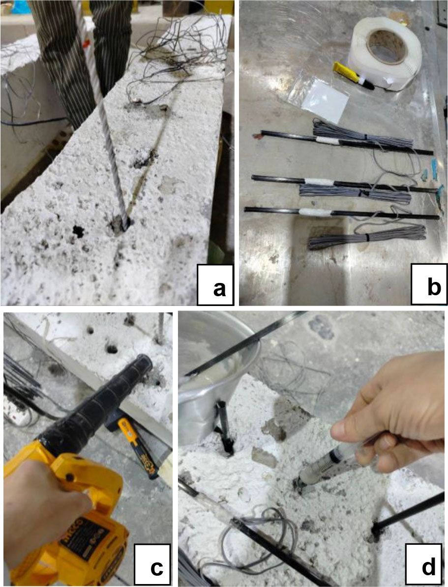
Figure 3:
Strengthening procedure of ETS CFRP bars technique; (a) Preparing holes using a drill, (b) Attaching a strain gauge to CFRP bars, (c) Cleaning the drilled holes by compressed air, (d) injecting the bonding adhesive into the holes and inserting CFRP bars
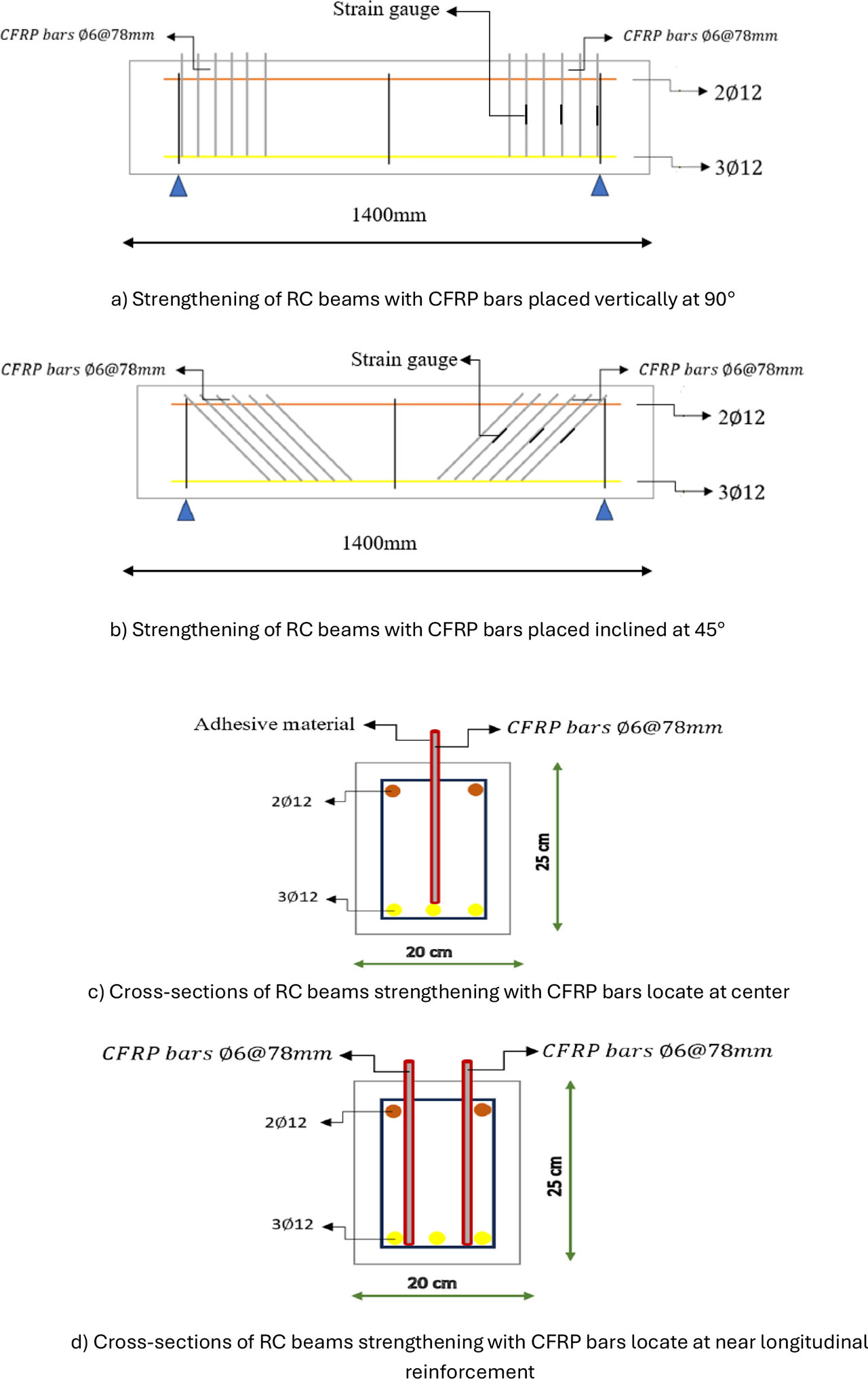
Figure 4:
The design of strengthening an RC beam with CFRP bars
2.3. Test Setup
To ensure shear failure occurs during testing, four-point loading was used to test the RC beams (Figure 5). The load was applied gradually until failure. The vertical displacement at mid-span was measured using displacement transducers. TML strain gauges were installed to monitor the strains at three locations: on the top of the front face of the concrete beam (Figure 5), at the mid-span section of the longitudinal steel reinforcement (Figure 5), and, for the ETS-strengthening CFRP bars, the strain gauge was placed at the anticipated location of the critical shear crack (Figure 3 a and b). The load was applied by a hydraulic jack with a maximum load capacity of 2000 kN at a 2kN loading rate. All specimens (except the control specimen) underwent two testing phases. In the first phase, the specimens were tested under a specific load (monotonic/repeated) to achieve a predetermined ratio of damage corresponding to 50% or 70% of the ultimate load of the (M-control) specimen. Strengthening was then performed using the ETS technique. The second phase: Approximately one week following the strengthening procedure, the specimens were tested under a monotonic load until failure.
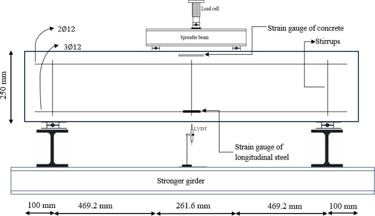
Figure 5:
Test setup and steel reinforcement details of the tested beams
2.4. Load Protocol of Repeated Loading
The deformation amplitude was set to 0.1 of the ultimate deformation observed in the monotonic scenario to initiate the fatigue cycle. For the first ten cycles, this amplitude was maintained. The deformation amplitude for the next three cycles was then raised to 1.2 times the first stage’s amplitude. The deformation amplitude increased by 0.2 in each succeeding stage. According to (Daud, 2015) (Jasim & Daud, 2024), this procedure was carried out until the specimens attained the intended damage levels of 50% and 70%. Figure 6 and Table 2 offer more information about this procedure. It is crucial to remember that the load protocol only considered the positive loading scenario. A modified technique suggested by (FEMA, 2007) was used to model the repeated load (Applied Technology Council, 2007).
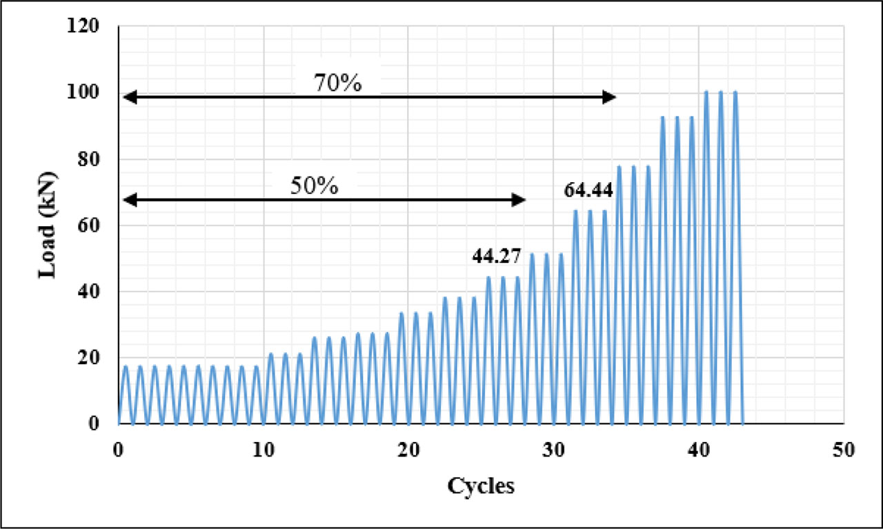
Figure 6:
Load vs. No. of cycles of repeated loading protocol for damaged ratios 50% and 70%
Table 2:
Repeated load protocol
| Stage | No. of cycles | Displacement (mm) | Load (kN) | Cumulative loading cycles | Amplitude |
|---|---|---|---|---|---|
| 0ne | 10 | 0.63 | 17.39 | 10 | 0.1 |
| Two | 3 | 0.76 | 21.29 | 13 | 1.2 |
| Three | 3 | 0.91 | 26.23 | 16 | 1.2 |
| Four | 3 | 1.09 | 27.42 | 19 | 1.2 |
| Five | 3 | 1.31 | 33.41 | 22 | 1.2 |
| Sex | 3 | 1.57 | 38.08 | 25 | 1.2 |
| Seven | 3 | 1.88 | 44.27 | 28 | 1.2 |
| Eight | 3 | 2.26 | 51.24 | 31 | 1.2 |
| Nine | 3 | 2.71 | 64.44 | 34 | 1.2 |
| Ten | 3 | 3.25 | 77.83 | 37 | 1.2 |
| Eleven | 3 | 3.9 | 92.77 | 40 | 1.2 |
| Twelve | 3 | 4.68 | 100.44 | 43 | 1.2 |
3. Results and Discussion
The most important results obtained from the experimental program are summarized in Table 3. Where Pu is the ultimate load, Δu and Δf are the displacements at ultimate load and at failure. The efficiency of the ETS technology was represented as a percentage as follows: , the term (Pu − Pu(ref.)) represents the increase in the ultimate load due to the CFRP-strengthened bars. The table also includes the maximum experimental shear strength for each specimen (Vmax. = 0.5 pu) and the maximum experimental shear strength provided by the CFRP-strengthened bars Vf(exp.). The latter was calculated by subtracting the total shear strength of the unstrengthened beam (Vexp.(ref.) = Vc + Vs), (e.i. shear force provided by stirrups Vs = 0) from the total shear strength of the beam strengthened by ETS CFRP bars technique (Vexp.(ETS) = 0.5 Pu). The last column in the table represents the secant stiffness (K75%) at 75% of the ultimate load (Pu) together with the corresponding displacement, as this value provides a meaningful, averaged measure of the structural stiffness in a highly nonlinear-after significant cracking and damage have developed, but before collapse. Unlike the initial tangent stiffness (which only reflects the undamaged or lightly cracked state), Moreover, secant stiffness is less sensitive to experimental noise compared with tangent stiffness, making it a reliable metric for assessing stiffness recovery or loss (Lin, 2025).
Table 3:
Experimental results of tested beams
| Specimen codes | Pu (kN) | Δu (mm) | Δf (mm) | Δ75% (mm) | The efficiency of the ETS (%) | Vmax (kN) | Vf(exp.) (kN) | |
|---|---|---|---|---|---|---|---|---|
| M- Control | 101.43 | 4.6 | 6.34 | 3.06 | - | 50.715 | - | 24.86 |
| M-50% | 88.99 | 4.34 | 5.39 | 3.04 | - | 44.495 | - | 21.95 |
| M-70% | 79.9 | 4.08 | 5.04 | 2.78 | - | 39.95 | - | 21.56 |
| MSC45-50% | 126.87 | 6.34 | 6.95 | 3.36 | 42.57 | 63.435 | 18.94 | 28.32 |
| MSC90-50% | 112.54 | 5.47 | 5.91 | 3.48 | 26.46 | 56.27 | 11.775 | 24.25 |
| MSN45-50% | 130.65 | 6.78 | 7.99 | 3.3 | 46.81 | 65.325 | 20.83 | 29.69 |
| MSN90-50% | 119.23 | 6.34 | 7.56 | 3.42 | 33.98 | 59.615 | 15.12 | 26.15 |
| MSC45-70% | 122.05 | 6.95 | 7.21 | 3.91 | 52.75 | 61.025 | 21.075 | 23.41 |
| MSC90-70% | 112.83 | 6.08 | 6.52 | 3.74 | 41.21 | 56.415 | 16.465 | 22.63 |
| MSN45-70% | 127.1 | 7.47 | 7.9 | 3.82 | 59.07 | 63.55 | 23.6 | 24.95 |
| MSN90-70% | 118.51 | 6.6 | 6.95 | 3.77 | 48.32 | 59.255 | 19.305 | 23.58 |
| F-50% | 82.18 | 4.26 | 5.13 | 3.12 | - | 41.09 | - | 19.75 |
| F-70% | 71.39 | 3.82 | 4.78 | 3.03 | - | 35.695 | - | 17.67 |
| FSC45-50% | 121.42 | 5.21 | 6.17 | 3.97 | 47.74 | 60.71 | 19.62 | 22.94 |
| FSC90-50% | 105.45 | 4.6 | 5.13 | 3.48 | 28.32 | 52.725 | 11.635 | 22.73 |
| FSN45-50% | 127.32 | 5.82 | 6.45 | 3.73 | 54.93 | 63.66 | 22.57 | 25.60 |
| FSN90-50% | 116.24 | 4.95 | 5.73 | 3.74 | 41.45 | 58.12 | 17.03 | 23.31 |
| FSC45-70% | 118.51 | 4.78 | 5.82 | 3.68 | 66 | 59.255 | 23.56 | 24.15 |
| FSC90-70% | 109.99 | 4.78 | 5.47 | 3.91 | 54.07 | 54.995 | 19.3 | 21.1 |
| FSN45-70% | 124.75 | 5.13 | 6.08 | 3.39 | 74.74 | 62.375 | 26.68 | 27.6 |
| FSN90-70% | 113.97 | 4.87 | 5.91 | 3.89 | 59.64 | 56.985 | 21.29 | 22 |
3.1. Series 1 (Monotonic Loading)
3.1.1. Load-displacement Curves
Figure 7 shows a comparison between the three specimens: M-Control, M-50%, and M-70%. It is clearly evident that a decrease in apparent stiffness and maximum shear capacity with an increase in the damage ratio. The reduction in stiffness was 11.7% and 13.3%, and for the maximum shear capacity was 12.3% and 21.2% for the pre-damaged specimens at 50% and 70%, respectively. This can be attributed to partial degradation of concrete and prior microcracking. These cracks limited the ability of the pre-damage specimen to undergo large deformations (Hamah-Ali, 2021).
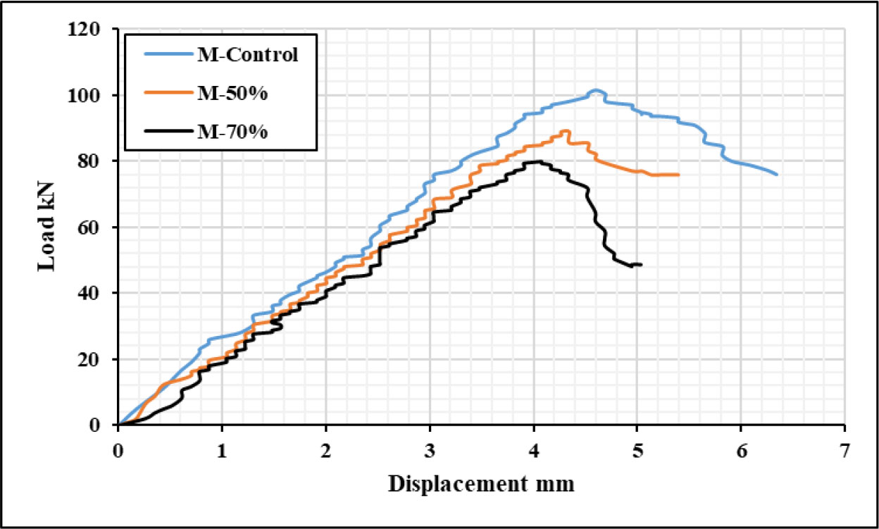
Figure 7:
Load vs. displacement curves for control beam and pre-damaged beam up to 50% and 70%
Figures 8 and 9 compare the 50% and 70% pre-damaged specimens with their reference pre-damaged specimens (M-50%) and (M-70%), respectively. The load vs. displacement behaviour shows that all specimens strengthened with ETS CFRP bars showed a significant improvement in maximum shear capacity by 42.6%, 46.8%, 26.5%, and 34% for the MSC45-50%, MSN45-50%, MSC90-50%, and MSN90-50%, respectively and 41.2%, 52.7%, 48.3%, and 59% for MSC90-70%, MSC45-70%, MSN90-70%, and MSN45-70%, respectively. These results confirm that the ETS bars contribute significantly to restoring the shear capacity even in severely damaged beams. Likewise, the results of the maximum experimental shear strength directly provided by the CFRP strengthening bars shown in Table 2 confirm that the CFRP bars are not only enhancing overall strength but are actively engaging in shear resistance mechanisms.
Across all tested specimens, the ETS-strengthened beams demonstrated substantial improvements in ultimate shear capacity, with efficiency values ranging from 26.4% to 59%. Additionally, the experimentally obtained shear contribution from the CFRP bars (Vf) reached up to 23.6 kN, further emphasizing the contribution of the ETS bars in enhancing load resistance. Notably, even in specimens with severe pre-damage levels of up to 70%, the ETS system maintained effective performance, indicating its ability to restore and upgrade shear capacity under compromised conditions. This overall improvement reflects the robustness and applicability of the ETS method for rehabilitating RC elements subjected to significant shear degradation. While the improvement in stiffness at ultimate load ranged from 18.81 to 20.57 kN/mm for strengthened specimens with a 50% damaged ratio and from 17.01 to 18.56 kN/mm for strengthened specimens with a 70% damaged ratio Higher stiffness (ranged 10.5%-35.3% for 50% pre damaged and 5%-15.7% for 70% pre damaged specimens) and ultimate shear strength result in more brittle shear failure and lower post-peak deformation capacity, which is a common trade-off documented in the literature (Haddad et al, 2019) (Hasan et al, 2024).
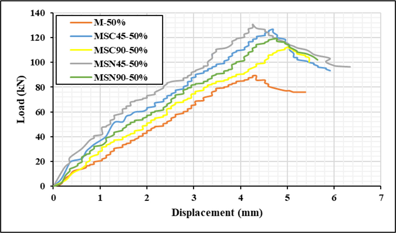
Figure 8:
Load vs. displacement curves for 50% pre-damaged specimens
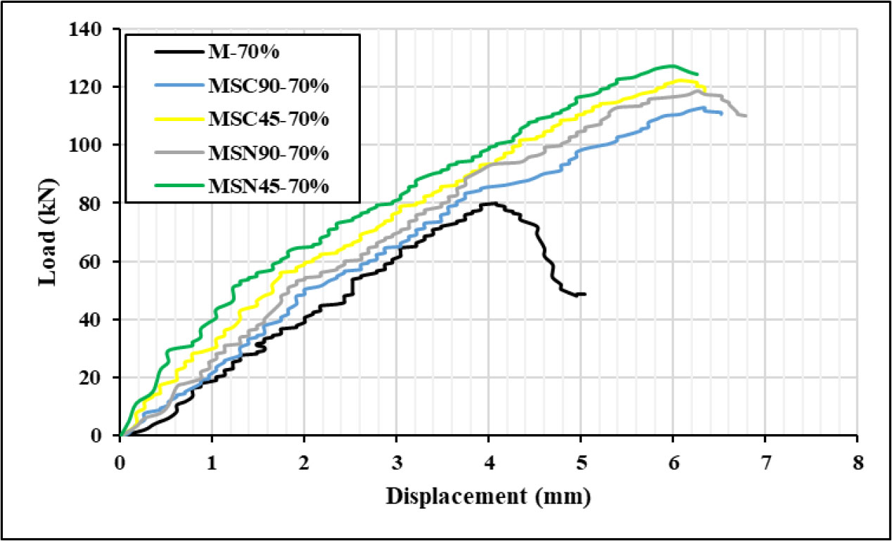
Figure 9:
Load vs. displacement curves for 70% pre-damaged specimens
3.1.2. Effect of Inclination Angle of CFRP Bars
The influence of pre-damage level on the effectiveness of CFRP bar inclination in enhancing shear capacity was clear in the test results. For beams subjected to 50% pre-damage, it was observed that strengthening with CFRP bars inclined at 45° resulted in a higher maximum shear capacity compared with beams strengthened using vertically installed (90°) CFRP bars. Specifically, the maximum shear capacity increased by 12.73% for the MSC45°-50% specimen and by 9.58% for the MSN45°-50% specimen relative to the MSC90°-50% and MSN90°-50% specimens. This enhancement can be attributed to the fact that, under limited diagonal-crack development, the inclined bars were more effective in intercepting developing cracks, mobilizing higher tensile forces along the fibre length, and improving the aggregate interlock mechanism—thereby enhancing the overall shear resistance (Murad, 2018).
A similar trend was observed for the 70% pre-damage level, where the specimens strengthened with 45° inclined CFRP bars demonstrated notable improvements in shear capacity. Specifically, the shear capacity increased by 7.24% for the MSN45°-70% specimen and by 8.17% for the MSC45°-70% specimen compared with their counterparts strengthened with vertically oriented CFRP bars (MSN90°-70% and MSC90°-70%, respectively). This improvement is attributed to the ability of the inclined CFRP bars to directly bridge the fully developed cracks, thereby restricting crack widening and sliding, and providing enhanced shear resistance despite the limited post-peak ductility (Turki, & Al-Farttoosi, 2023).
3.1.3. Effect of the Location of CFRP Bars
The effectiveness of shear strengthening in pre-damaged beams is greatly influenced by the location of ETS CFRP bars. In the case of 50% pre-damage beams, the increase in shear strength capacity was 3% and 6% for the MSN45°-50% and MSN90°-50% specimens, respectively, compared to the MSC45°-50% and MSC90°-50% specimens, respectively. When the damaged ratio increased to 70%, the location near the reinforcement was also effective in improving shear resistance, 4.14% and 5.03% for MSN45°-70% and MSN90°-70% specimens, respectively, compared to MSC45°-70% and MSC90°-70% specimens. Since the concrete in the centre of the beam is more severely cracked and degraded, this weakens the bond and limits the efficiency of the central CFRP bars. Therefore, placing the bars near to the longitudinal reinforcement provides direct resistance along the primary shear failure paths, as the diagonal shear cracks frequently propagate near the longitudinal reinforcement due to the elevated bond stresses in that zone.
3.1.4. Strains in Concrete, Steel Reinforcement and CFRP Bars
Pre-damage has a major impact on the strain development of both concrete and steel reinforcement materials, as shown by the experimental data of total strain (Figures 10 and 11). Concrete and steel stresses gradually grew with load in the undamaged (M-control) specimen, exhibiting typical elastic–plastic transitions until peak failure. When reloading began, pre-damaged beams showed higher starting strains, which were indicative of residual deformations from previous loading. In particular, M-70% displayed the greatest initial strains in both materials as well as the smallest incremental strain capacity, suggesting a significant decrease in deformation potential as a result of widespread pre-damage.
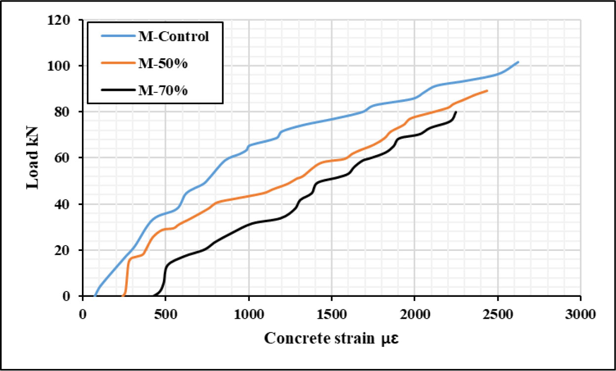
Figure 10:
Load vs. concrete strain of control damaged/undamaged specimens
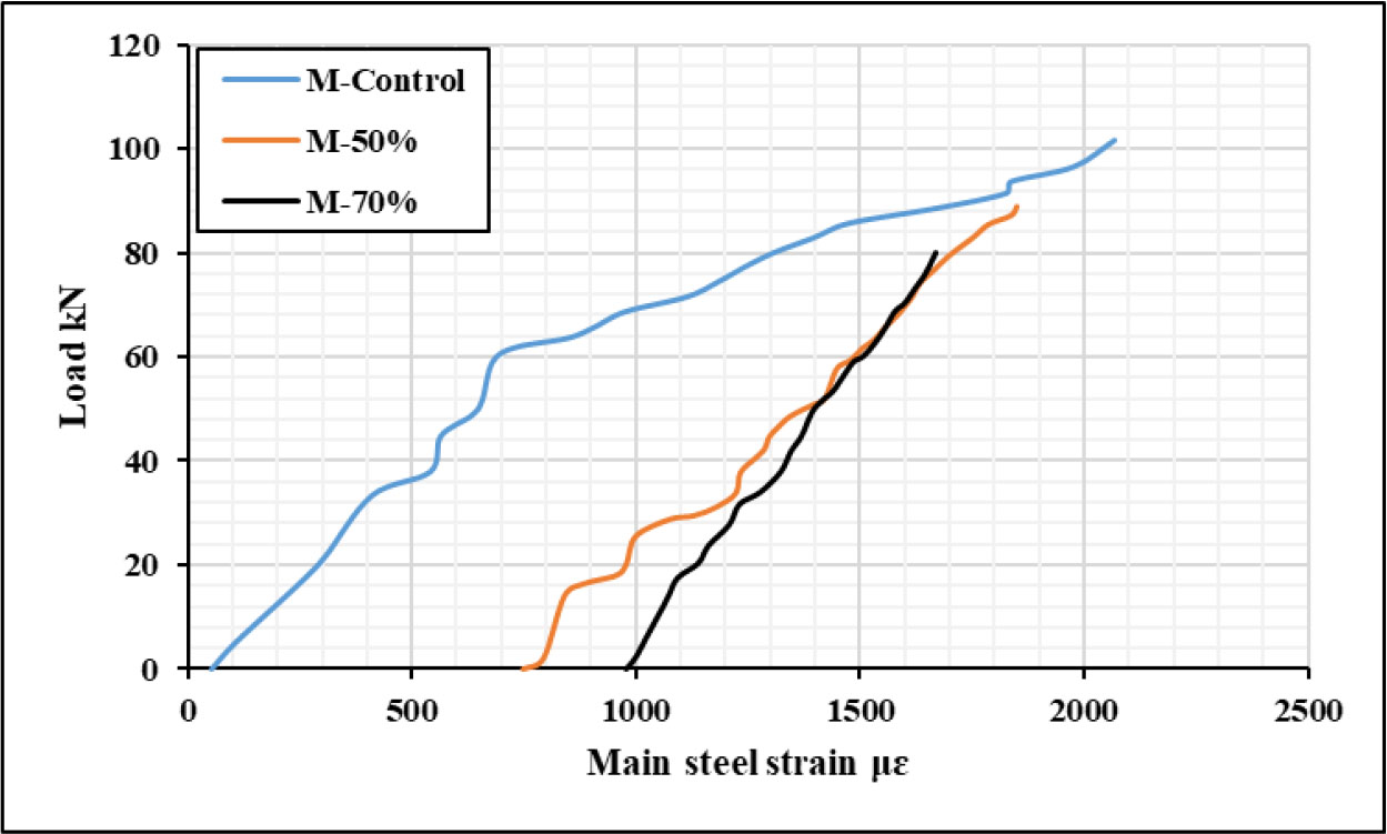
Figure 11:
Load vs. main steel strain of control damaged/undamaged specimens
The results of total strain for concrete and main steel of 50% and 70% pre-damaged beams are shown in Table 4.
Table 4:
Total strain of specimens (series 1)
| Specimen code | Concrete strain μɛ | Steel strain μɛ | CFRP strain μɛ |
|---|---|---|---|
| M-50% | 2435 | 1848 | - |
| MSC45-50% | 2631 | 2578 | 1561 |
| MSC90-50% | 2553 | 2513 | 1207 |
| MSN45-50% | 2658 | 2612 | 1653 |
| MSN90-50% | 2582 | 2553 | 1423 |
| M-70% | 2245 | 1669 | - |
| MSC45-70% | 2514 | 2583 | 1315 |
| MSC90-70% | 2408 | 2463 | 1064 |
| MSN45-70% | 2554 | 2634 | 1572 |
| MSN90-70% | 2476 | 2551 | 1209 |
The experimental findings demonstrated that the initial damage ratio had a visible effect on the strain responses of steel and concrete at ultimate load. Significant decreases in the measured strain values were observed for the control specimens when the pre-damage level changed from 50% to 70%. In particular, the steel strain dropped from 1848 με to 1669 με, and the concrete strain dropped from 2435 με at 50% damage to 2245 με at 70% damage. This decrease suggests that specimens exposed to greater pre-damage lost their ability to recover from deformity and stiffness, which resulted in an earlier localization of strain and a reduced total strain capacity at failure.
Such conduct is consistent with findings by (Al-Mahaidi & Kalfat, 2018), who pointed out that pre-existing damage reduces the bond integrity between reinforcement and concrete, leading to reduced strain development under reloading. In severely damaged specimens, partial debonding and the spread of microcracks along the steel–concrete interface further reduces the effectiveness of stress transfer, resulting in a more brittle failure response. The strengthening specimens, on the other hand, showed greater strain values than the corresponding unstrengthened (control) beams in the same damage ratio. For example, the strengthened beams’ average concrete and steel stresses were higher than the control specimen’s at 50% damage, suggesting better load redistribution and increased deformation capacity. The ETS CFRP bars strengthening technique assisted in partially restoring the strain capacity lost as a result of significant pre-damage, improved confinement, limited the development of cracks, and improved the composite action between steel and concrete, and a similar pattern was seen for the 70% damage ratio (Hamah-Ali et al, 2021).
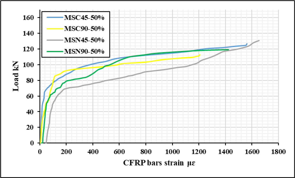
Figure 12:
Load vs. CFRP bars strain of 50% pre-damaged beams
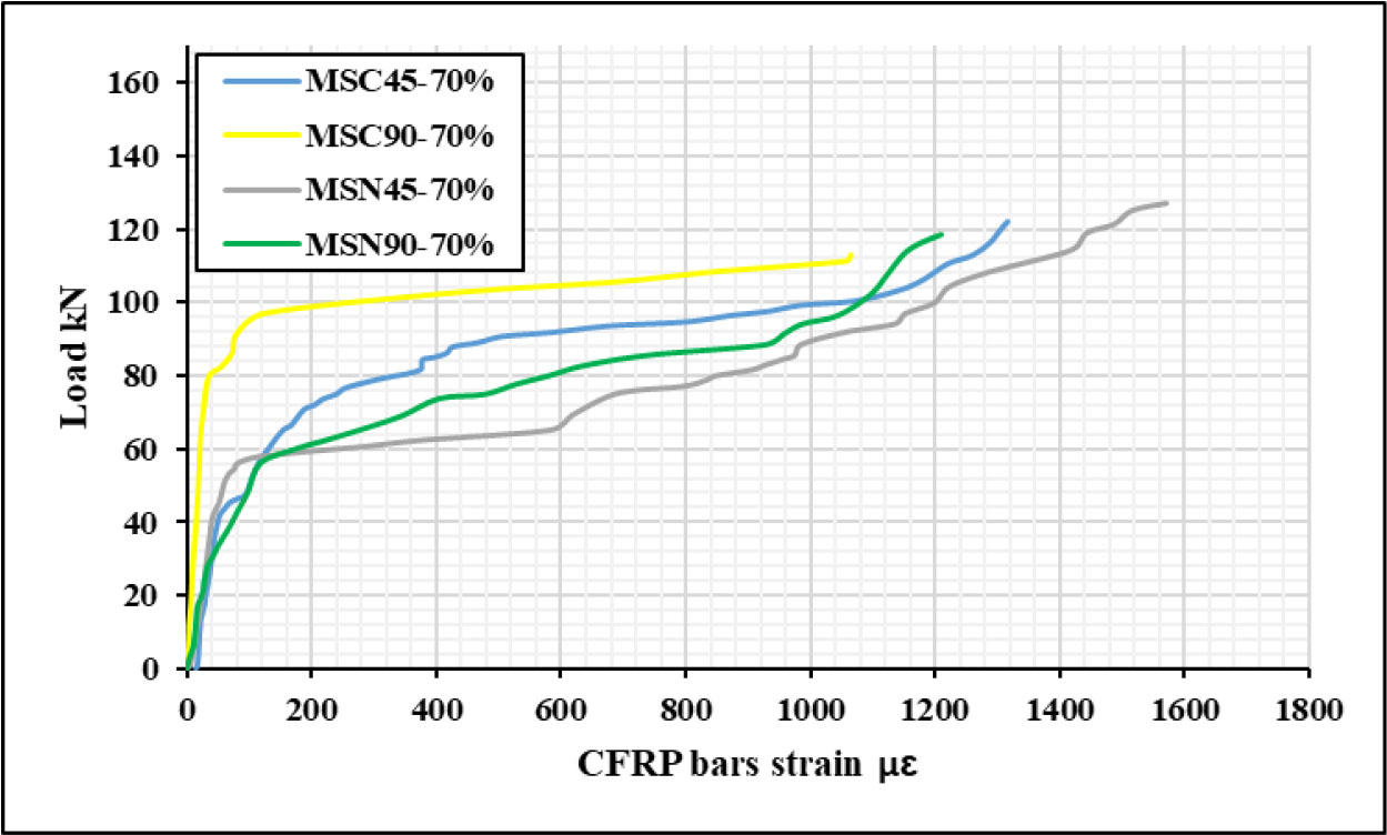
Figure 13:
Load vs. CFRP bars strain of 70% pre-damaged beams
Figures 12 and 13 showed the effect of both the inclination angle and the location of the strengthening bars on the strain behaviour of the CFRP bars for pre-damage ratios of 50% and 70%, respectively. The CFRP strain values of specimens reinforced with inclined CFRP bars at 45° were often greater than those of specimens reinforced at 90°. Because during shear action, inclined CFRP bars were more successfully engaged, improving confinement in the key shear zones and redistributing stress. At the same inclination and damage level, specimens with CFRP bars positioned near the longitudinal reinforcement had greater strain values than those positioned in the centre of the cross-section. Because these bars were close to the main crack zones and the tensile reinforcement, they can mobilize more strain and make a greater contribution to the load-carrying capacity after rehabilitation (Hamah-Ali et al, 2021).
3.1.5. Failure Modes
The failure mode of the 50% and 70% pre-damaged specimens under a monotonic load is shown in Figure 14. Where it is clear that shear failure is dominant, characterized by the formation of a major diagonal crack extending between the loading and support zones, accompanied by secondary flexural cracks in the tension region, which is normal in the case of reinforcement without stirrups. which prevented sufficient redistribution of stresses once the principal diagonal crack formed. Consequently, after crack propagation, crushing of the concrete strut occurred, leading to brittle collapse before the full utilization of CFRP or longitudinal steel ductility.
Therefore, while the ETS CFRP technique did not change the fundamental failure mode, the enhanced CFRP strain response demonstrates the active participation of the ETS bars in resisting shear forces and bridging diagonal cracks. The measured CFRP strains confirm that the bonded CFRP bars carried a significant portion of the shear load and delayed the propagation of major shear cracks. This behaviour reflects efficient bond interaction and stress transfer between the CFRP and the surrounding concrete, which in turn improved the stiffness and load-carrying capacity of the strengthened members. Similar findings were reported by (Obaidat et al, 2010) who emphasized that ETS or embedded FRP systems enhance shear capacity mainly through crack-bridging and confinement mechanisms, even though the ultimate mode of failure often remains governed by diagonal shear cracking in the absence of shear reinforcement.
3.2. Series 2 (Repeated Loading)
3.2.1. Load-displacement Curves
Figure 15 shows the comparison of the damaged specimens under repeated loading with the control specimen. The pre-damaged beams exhibited a clear reduction in shear strength, carrying capacity, and stiffness. The reduction in ultimate load was 18.98% and 29.62% for the F-50% and F-70% specimens, respectively. The cumulative fatigue damage from repeated loading, which gradually results in microcracking, stiffness degradation, and weakening of the bond between the concrete matrix and reinforcing steel, is responsible for this reduction. lead to a gradual lowering of the beam’s residual load-carrying capacity (Liu et al, 2018). The initial slope of the load-displacement curve also showed a decrease in beam stiffness as the pre-damaged ratio increased. This pattern is consistent with other research showing that internal cracks and microstructural degradation inside the concrete cause a progressive loss of elastic modulus and bond efficiency as a result of repetitive loading (Chen et al, 2024). Both the F-50% and F-70% curves demonstrated softer responses, indicating stiffness deterioration by 19% and 29.62% for F-50% and F-70% respectively, under fatigue loading, but the control specimen retained a stiffer response.
However, the damage from repetitive loading not only decreased the capacity to absorb energy but also encouraged stiffness loss and early fracture localization, resulting in early brittle behaviour. Similar findings have been published by (Ruiz et al, 2015) and (Yi et al, 2010), who discovered that widespread microcrack coalescence and loss of confinement caused by high fatigue-damage levels restrict the post-peak deformation capacity of reinforced concrete.
Strengthening the pre-damaged beams in Figures 16 and 17 revealed significant enhancements in deformation performance and shear capacity. When compared to the control, the ultimate load of strengthening specimens increased by 28% to 55% at the 50% damage ratio. Similarly, load improvements for the 70% damage level were between 54% and 75% as a result of strengthening. These findings demonstrate how well the ETS method works to restore shear strength even in cases of severe damage. This is consistent with the observations of (Bui et al, 2024) who emphasized that the ETS-FRP technique remains effective in restoring shear strength even when high pre-damage levels are present. The impact is therefore more noticeable where the damage is pronounced.
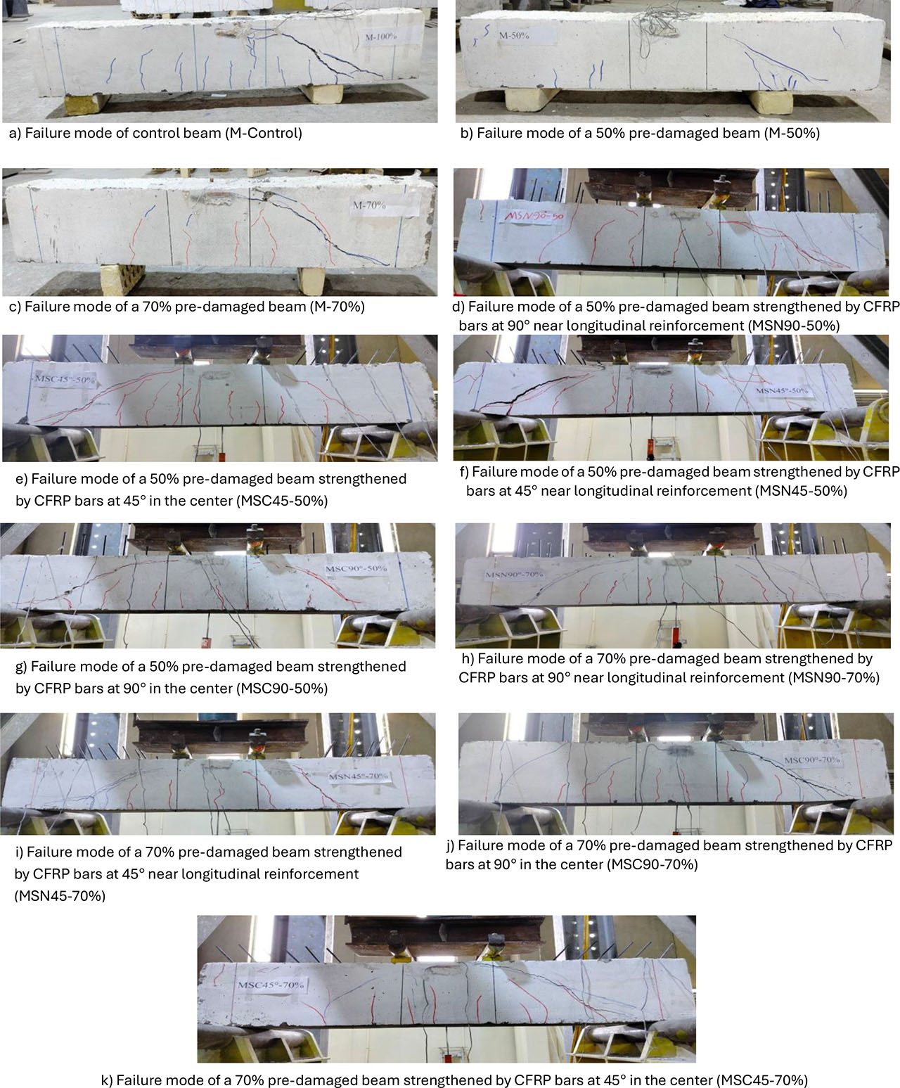
Figure 14:
Failure mode of specimens (Series 1-under monotonic damage)
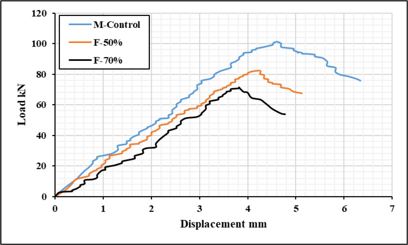
Figure 15:
Load vs. displacement curves for the control beam and pre-damaged repeated loading beam up to 50% and 70%
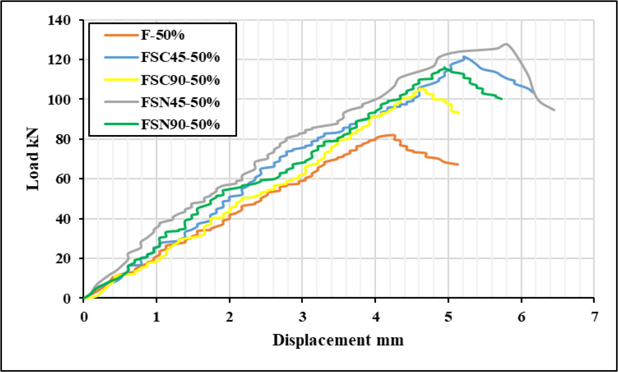
Figure 16:
Load vs. displacement curves for 50% pre-damaged repeated loading specimens
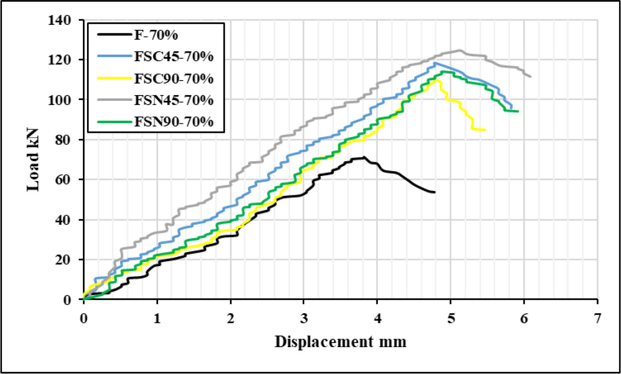
Figure 17:
Load vs. displacement curves for 70% pre-damaged repeated loading specimens
3.2.2. Effect of Inclination Angle of CFRP Bars
Specimens with 45°-angled CFRP bars showed the greatest improvement, especially those positioned near the longitudinal reinforcement (FSN45-50% and FSN45-70%), which produced the highest shear loads (63.66 kN and 62.375 kN, respectively). This behaviour is in line with research by (NAQEE & DAUD, 2024) and (Alhilli & Al-Farttoosi, 2023), who showed that because inclined CFRP reinforcement better intercepts diagonal shear cracks and mobilizes tensile resistance along the principal stress direction, it increases shear strength more effectively than vertical alignment. Conversely, specimens reinforced with 90° vertical bars (FSC90 and FSN90 series) showed comparatively less benefits because the perpendicular alignment contributes less to the shear stress field and offers less effective crack bridging (Alhilli & Al-Farttoosi, 2023).
3.2.3. Effect of the Location of CFRP Bars
According to the experimental results, CFRP bars are more effective in restoring shear strength for pre-damaged repeated loading beams when positioned near to the main reinforcement than when placed in the centre, this improvement results in more efficient transmission of tensile forces across the damaged area, enhancing aggregate interlock, delaying crack propagation, and improving their bridging (NAQEE & DAUD, 2024). The maximum shear strength increased by 10.23% and 4.86% in the case of the 50% pre-damage specimens, FSN90-50% and FSN45-50%, compared to the FSC90-50% and FSC45-50% specimens, respectively. While the increase in the shear capacity of 70% pre-damage specimens was 5.27% and 3.62% for FSN45-70% and FSN90-70% compared to the FSC45-70% and FSC90-70% specimens, respectively.
3.2.4. Strains in Concrete, Steel Reinforcement, and CFRP Bars
By observing Figures 18 and 19, it is a clear progressive decrease in the strain values of both steel and concrete, with the increase of the pre-damage ratio from 50% to 70%. Since strain represents a measure of internal deformation and crack propagation, this decrease indicates a deterioration of the bond between the concrete and steel, and consequently a reduced capacity for stress transfer after fatigue damage (Alhilli & Al-Farttoosi, 2023) (Aslani & Jowkarmeimandi, 2012).
Table 5:
Total strain of specimens (Series 2)
| Specimen code | Concrete strain μɛ | Steel strain μɛ | CFRP bars strain μɛ |
|---|---|---|---|
| F-50% | 2412 | 1823 | - |
| FSC45-50% | 2576 | 2549 | 1543 |
| FSC90-50% | 2517 | 2487 | 1174 |
| FSN45-50% | 2603 | 2586 | 1638 |
| FSN90-50% | 2554 | 2521 | 1408 |
| F-70% | 2221 | 1647 | - |
| FSC45-70% | 2493 | 2568 | 1302 |
| FSC90-70% | 2381 | 2441 | 1042 |
| FSN45-70% | 2531 | 2621 | 1557 |
| FSN90-70% | 2446 | 2534 | 1186 |
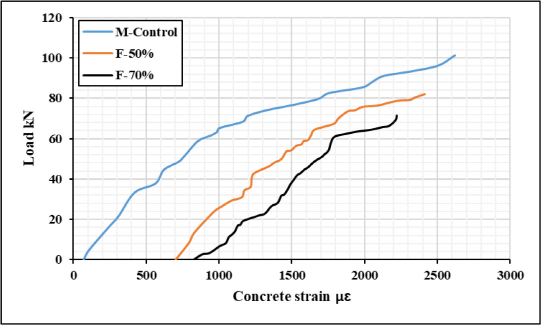
Figure 18:
Load vs concrete strain of control damaged/undamaged specimens
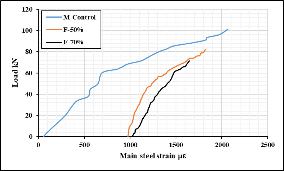
Figure 19:
Load vs main steel strain of control damaged/undamaged specimens
The ability of embedded through-section CFRP reinforcement to restore the structural performance of pre-damaged specimens is amply demonstrated by the strain responses of both steel and concrete for the strengthened beams. The improvement for specimens of the moderately damaged 50% strengthened with CFRP bars was 39.7% and 6.8% for the FSC45-50%, 36.3% and 4.4% for the FSC90-50%, 41.8% and 8% for the FSN45-50%, and 38.2% and 5.9% for the FSN90-50%for steel and concrete, respectively. Similarly, for beams with a high damaged ratio of 70%, the improvement was 55.8% and 12.2% for the FSC45-70%, 48.2% and 7.2% for the FSC90-70%, 59.2% and 13.9% for the FSN45-70%, and 53.9% and 10.1% for the FSN 90-50% for steel and concrete, respectively. Results in Table 5 clearly show that the CFRP reinforcement successfully recovered and even improved the strain performance of concrete and steel under monotonic loading, compensating for the decreases brought on by earlier fatigue damage.
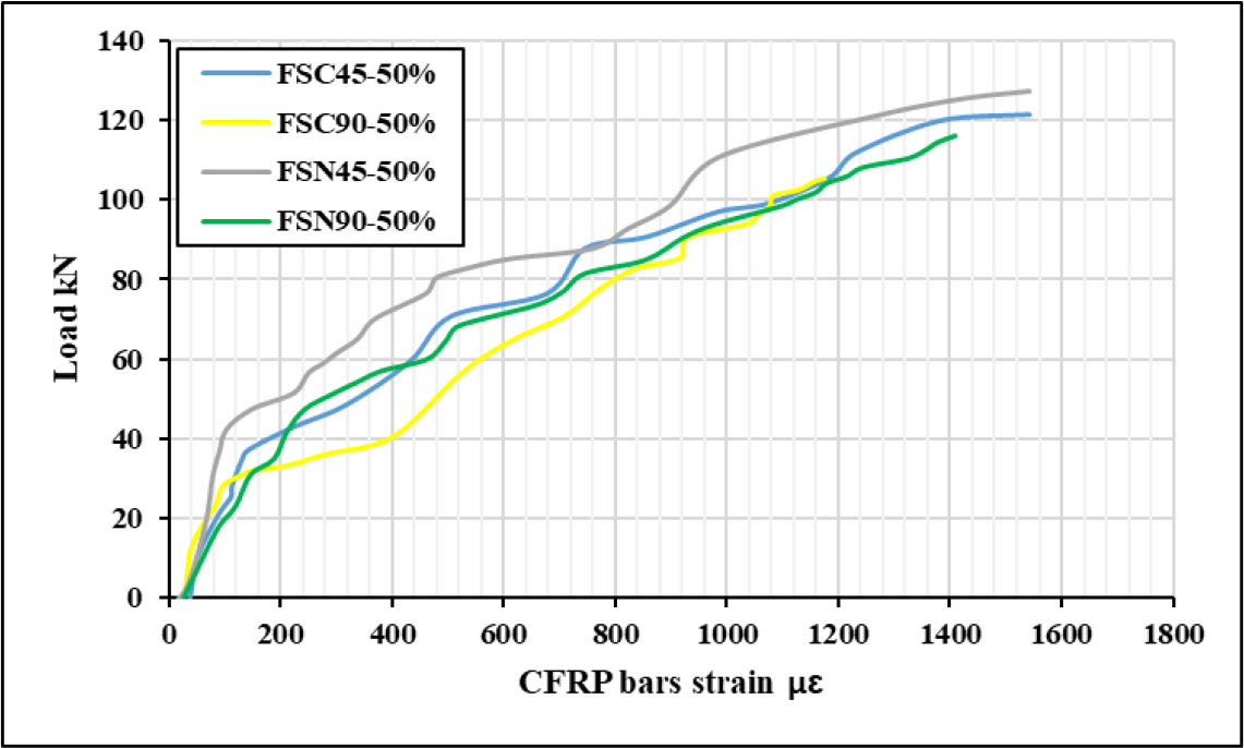
Figure 20:
Load vs. CFRP bars strain of 50% pre-damaged beams
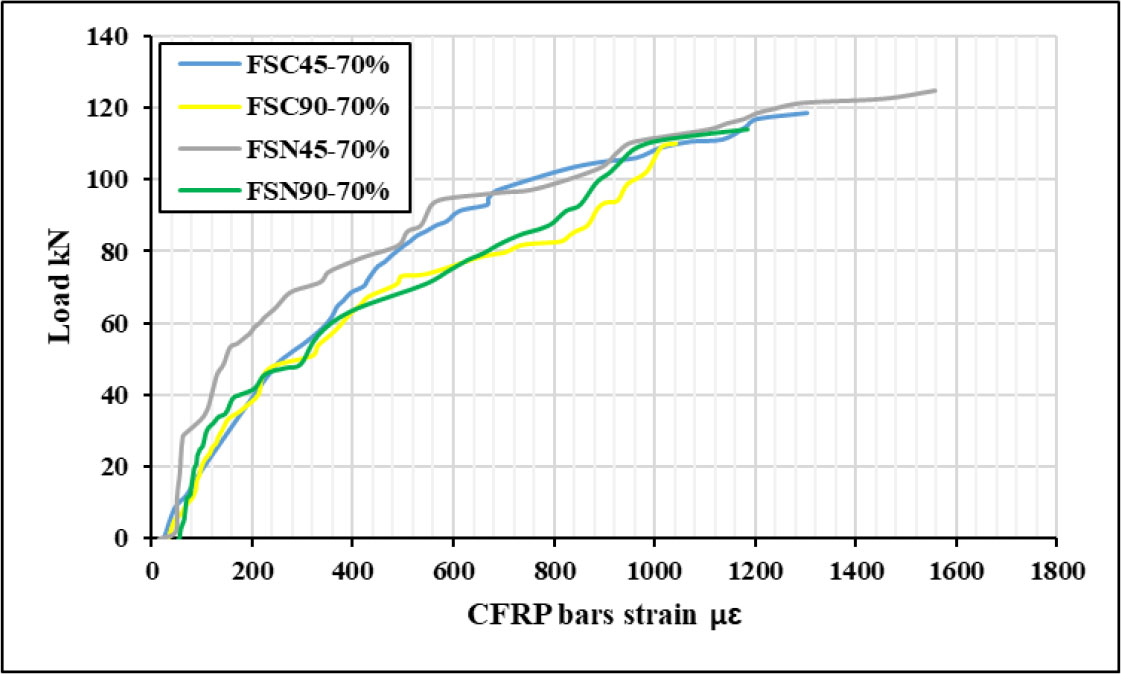
Figure 21:
Load vs. CFRP bars strain of 70% pre-damaged beams
The CFRP bars’ strain response for beams that were 50% and 70% pre-damaged under repeated loading (Figures 20 and 21) shows a definite influence on the CFRP bars’ location and inclination angle. The specimen FSN45 exhibited the maximum strain among the 50% and 70% pre-damaged specimens, suggesting that near longitudinal bars positioned CFRP bars at 45° were more successfully mobilized under shear stresses. Better stress transfer and improved interaction between the CFRP bars and the surrounding concrete matrix were made possible by this arrangement. On the other hand, specimens with 90°-oriented CFRP bars FSC90 showed a lower strain value for both damaged ratios, indicating a smaller contribution to the resistance of diagonal tension and shear loads. In general, the CFRP strain capacity was significantly lower in the group of specimens that had 70% pre-existing damage, demonstrating the negative impact of greater pre-existing damage on the effectiveness of the strengthening system. The more severe cracking and restricted load redistribution ability inside the severely damaged concrete zones are the reasons for this strain decrease, which ranges between roughly 4.9% and 15.8% when compared to the 50% damage group. Furthermore, the CFRP bars were probably engaged later in the loading process and experienced premature slip at greater damage levels, which decreased their efficacy in strain development.
3.2.5. Failure Modes
A prominent diagonal shear crack and a few minor flexural cracks at midspan were present in all specimens that had previously been damaged by repeated load and strengthened with ETS (Figure 22). Even though the ETS strengthening approach is meant to increase shear resistance by continuously reinforcing the shear region with CFRP, all specimens eventually failed to shear. Because there is no transverse steel reinforcement and the existence of pre-fatigue damage, this behaviour is seen as typical and expected. ETS strengthening increased structural stiffness and retarded the development of cracks, but it was unable to completely prevent shear failure in beams that had previously sustained damage and not substitute for stirrups, according to comparable findings from another research (Aslani & Jowkarmeimandi, 2012). Despite the inclusion of ETS bars, studies show that the cumulative impacts of pre-existing microcracks and repeated deterioration considerably diminish the bond efficiency between CFRP and concrete, resulting in shear-dominated failure (Chen et al, 2018).
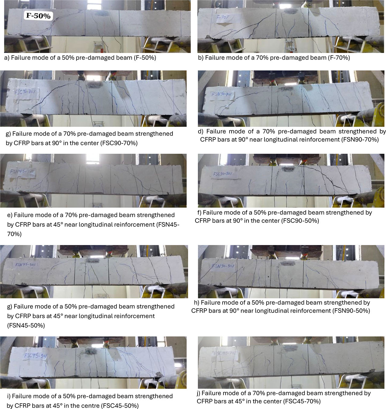
Figure 22:
Failure mode of specimens (Series 2 - under fatigue damage)
4. Conclusion
Considering the experimental results presented in this study, the following conclusions can be drawn regarding the performance and behaviour of damaged reinforced concrete beams under monotonic and repeated loading and strengthened using the ETS technique.
Strengthening pre-damaged RC beams with ETS CFRP bars significantly increased ultimate shear strength, with gains up to 59.07% for 70% pre-damaged specimens under monotonic loading and 74.74% for 70% pre-damaged specimens under repeated loading, even without conventional internal steel stirrups.
The strengthening efficiency was greatly impacted by the CFRP bars’ inclination angle. Under monotonic and repetitive stress, beams reinforced with 45° inclined bars performed better at both 50% and 70% pre-damage levels. When compared to vertically embedded bars, this orientation offered improved shear resistance and stress redistribution.
Shear enhancement is significantly influenced by the positioning of ETS CFRP bars. For both 50% and 70% pre-damaged beams, placing the bars close to the longitudinal steel reinforcement produced the highest shear performance under monotonic and repetitive loading, delayed failure, and maximized the effectiveness of strengthening
The strain results under both monotonic and repeated loading revealed that specimens with 45° inclined CFRP bars placed near the longitudinal steel reinforcement exhibited the highest strain values in concrete, steel, and CFRP bars. This configuration enhanced the compatibility of deformation among materials, improved confinement around the tensile zone, leading to better overall composite action and delayed cracking development.
Due to the presence of previous damage and the absence of shear reinforcement, shear failure was the predominant and expected mode for all pre-damaged (monotonic/repeated) beams. However, the ETS CFRP bars successfully inhibited diagonal cracking, increased shear resistance, and preserved structural integrity until failure.
Acknowledgements
The authors would like to express their sincere appreciation to Al-Nahrain University for providing the laboratory facilities and technical support that enabled the experimental work of this research.
Notes
[1] Author Contributions
R.A.H. conducted the experiments, collected and interpretation data, and manuscript drafting. R.A.D. conceived and designed the study and supervised the project. Both authors critically reviewed and approved the final version of the manuscript and agreed to be accountable for all aspects of the work.