

1. Introduction
Cement is the second most widely used resource after water due to its crucial role in concrete structures. One of the most significant applications of these structures is in civil engineering infrastructure (Taher et al., 2024). With the considerable technological advancements experienced across various sectors, these structures are evolving; there is a push for the development and expansion of innovative ideas to create advanced systems that address current challenges, keep pace with these developments, and provide alternatives to existing systems, all while considering sustainability and cost. Concrete structures are known to face deterioration issues that can be recurrent, including stress from loads, temperature fluctuations, aging, cracking, water infiltration, and related durability concerns such as carbonation, corrosion, sulphate attack, and cyclic freezing/thawing (Chung, 2020; DING, 2021; Han et al., 2008; Wang et al., 2023; Zhang et al., 2018). Consequently, there is an urgent need for technology that enables structures to self-monitor damage caused by these factors, known as structural health monitoring (SHM), within a broader framework called engineered cementitious composites (ECC). This emerging system aims to utilize self-sensing technology rather than conventional electronic methods that are often embedded within concrete. These typical electronic solutions tend to be short-lived and exhibit limitations regarding durability, sensitivity, and compatibility with concrete structures, along with high costs associated with installation and maintenance (Chen & Chung, 1993; Chen & Chung, 1996; Han et al., 2015; Musa et al., 2025; Xing et al., 2025). Efforts in this field seek to transform the traditional concrete structure, known for its non-functional cementitious system, into a smart, multi-functional system for applications such as pavement construction, enabling immediate damage detection, reducing maintenance expenses, and extending service life while combining superior mechanical behaviour with functional performance (Abdullah et al., 2022; Abdullah et al., 2023; Al-Dahawi, Öztürk, et al., 2016; Al-Dahawi et al., 2024; Bekzhanova et al., 2021; Hasan B. Birgin et al., 2021; Hasan Borke Birgin et al., 2021; Han et al., 2017). Such goals can be achieved by injecting conventional cementitious matrices with various types of multi-sized electrically conductive materials (Al-Dahawi et al., 2017; Chung, 2021; Ding et al., 2022; Hussain et al., 2022; Papanikolaou et al., 2020; Roopa & Hunashyal, 2021; Thomoglou et al., 2022; Wang & Aslani, 2022; Wen & Chung, 2007; Yagoub et al., 2022). These additives include a wide range of conductive fillers, most notably those based on carbon at the fibre, micro, and nanoscale (e.g., carbon fibres, carbon nanofibers, graphite, carbon black, carbon nanotubes, graphene nanoplatelets, and activated carbon) or metal fillers (e.g., steel fibres and nano/micro powders of iron, copper, nickel, and aluminium) (D’Alessandro et al., 2023; Dinesh et al., 2021; Dinesh, Suji, et al., 2023a, 2023c; Dong et al., 2016; Dong et al., 2021; Suchorzewski et al., 2020; Wang et al., 2020; Xu et al., 2022). The evaluation of a specific smart matrix is based on what is known as the "fractional change in electrical resistance" (FCER), a relative measure of the matrix’s damage-sensing quality and the compatibility of the conductive filler with the system. To obtain FCER values, it is necessary to subject the innovative cementitious composites to various loading scenarios (e.g., compressive and flexural strength, direct and indirect tensile strength, as well as cyclic loading under compressive and flexural stresses, etc.). Most literature on the manufacture of smart concrete mixtures has utilized a multi-experimental approach. This involves injecting the concrete matrix with either a single or hybrid conductive filler in various ways. These methods include adding the entire conductive dosage to the mixture or partially replacing one of the raw components of concrete, such as cement, sand, or gravel (Abdullah et al., 2022; Abdullah et al., 2023; Al-Dahawi et al., 2024; D’Alessandro et al., 2023; Dinesh, Suji, et al., 2023a, 2023c; Xu et al., 2022). The importance of the hybrid matrix lies in the synergistic effects of the types of fillers incorporated into it, which result in significant improvements in both mechanical and electrical properties (Al-Dahawi et al., 2024; Al-Mulla et al., 2024; Elseady et al., 2024; Hao et al., 2023; Lu et al., 2023; Luo et al., 2023; Ma et al., 2024; Roshan et al., 2024). Carbon, both fibre - and particulate-based, is among the most important of these additives. Meanwhile, activated carbon (AC) is emerging as an additive with exceptional properties that make it a promising candidate for smart concrete structural applications. The importance of AC lies in its sustainability, cost-effectiveness, and impressive pozzolanic activity. Sustainability features include the fact that AC is manufactured from waste from natural organic sources, making it environmentally friendly. The benefits of AC in intelligent concrete structures include (i) significantly lower costs and greater market availability compared to most alternative carbon-based materials (Górski & Safuta, 2025; Liu et al., 2025; Maimaitituersun et al., 2025; Musa et al., 2025; Neme et al., 2022; Triana-Camacho, D’Alessandro, et al., 2024; Triana-Camacho, Miranda, et al., 2024), (ii) the potential for in-house manufacturing using agricultural byproducts such as date pits, tamarind seeds, or walnut shells (Al-Qaessi & Abu-Farah, 2010; Arena et al., 2016; Chin et al., 2020),. (iii) effectiveness at low dosages, which reduces the high costs and workability issues often associated with other fillers (Justo-Reinoso et al., 2018; Zheng et al., 2017), and (iv) outstanding self-sensing properties even at minimal application levels (Dinesh, Suji, Pichumani, et al., 2023; Wang & Aslani, 2021). Numerous research studies have explored various aspects of cementitious systems incorporating AC. In their investigation, Frías et al. (2012) found that adding 10–20 wt.% AC into cement systems did not affect the initial setting time, although there were slight reductions in compressive strength. The results from (Lekkam et al., 2019) indicated that small amounts of AC (≤2%) could enhance mechanical properties. Chin et al. (2020) reported similar findings, demonstrating that the inclusion of AC improves the performance of cementitious composites under compressive and splitting stresses, as well as their density and conductivity. Na et al. (2021) analysed several AC concentrations ranging from 0.5% to 10% and discovered that increases up to 1.5% improve strength and early durability. Wang and Aslani (2021) studied the strength and electrical performance of cementitious mixtures containing AC at 0.5%, 1%, 2%, and 4% wt., concluding that 2% AC optimized mechanical performance, while 4% significantly enhanced electrical conductivity. Dinesh, Suji, Pichumani, et al. (2023) noted that AC reduces the compressive strength and resistivity of cementitious composites due to localized hydration and carbon buildup. The findings suggest that AC-based cement composites are suitable for monitoring structural deformation. Incorporating electrically conductive fibres into the cement-based system is crucial for the effective operation of a conductive network. Without these conductive fibres, piezoresistivity is either minimal or non-existent, which complicates directional alterations (Chung, 2016; Parlayıcı et al., 2025; Penna et al., 2025; Tu et al., 2025; Xing et al., 2025). Ding et al. (2016) found that carbon fibres significantly affect the matrix’s response to bending loads and enhance the electrical network within it. Their findings suggest a linear relationship between crack opening displacement and the FCER. Chen et al. (2017) reported that the combination of carbon fibres with carbon black in a hybrid configuration greatly improves the electrical conductivity of the resulting structures (7.34 ohms) and increases their load-bearing capacity. Donnini et al. (2018) demonstrated that integrating carbon fibres into cement mortar significantly reduces electrical resistance to below 150 Ω cm when subjected to applied stresses, including cyclic compression loading. The strategic combination of particle and fibres filler creates a robust and synergistic conductive network, enabling the composite to exhibit a piezoresistive response where electrical resistance changes with mechanical stress. This mechanism is illustrated in Figure 1.
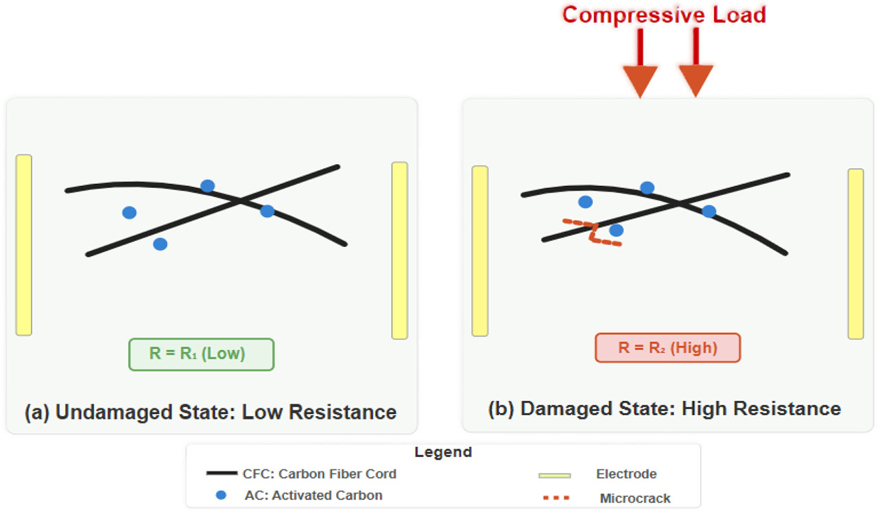
Figure 1:
Diagram of the piezoresistive self-sensing mechanism in the proposed hybrid ECC: (a) Undamaged condition: low-resistance conductive network (R1), and (b) Damaged condition under load: high-resistance conductive network (R2)
While the individual benefits of activated carbon (AC) in terms of cost-effectiveness and carbon fibre cord (CFC) in creating a well-documented strong electrically conductive network are recognized, there is a critical research gap in systematically exploring their hybrid synergy, particularly within engineered cementitious composite (ECC) matrices. Additionally, the vast majority of studies incorporate conductive filler by replacing cement or fine aggregates, a technique that may weaken the core mix design. This study addresses these gaps by introducing, for the first time, a new hybrid filler system where both AC and CFC are directly integrated into the ECC matrix. This direct addition method offers a more practical and less disruptive path to enhancing functionality. The primary goal is to design a balanced, high-performance, and cost-effective self-sensing matrix by optimizing the AC to CFC ratio. By focusing on the matrix level—a vital yet underexplored advancement – this work provides a crucial step toward creating next-generation ECC with superior and more reliable damage-sensing capabilities for real-world SHM applications.
2. Experimental Program
This section provides a detailed overview of the manufacturing stages for smart mixtures, beginning with the base materials and fillers discussed in this paper, followed by the mixing ratios and the optimal method for the mixing process. The concluding part of this section outlines the laboratory tests, categorized into two main areas: strength testing and the mixtures’ ability to sense under various stress conditions. Figure 2 illustrates this information.
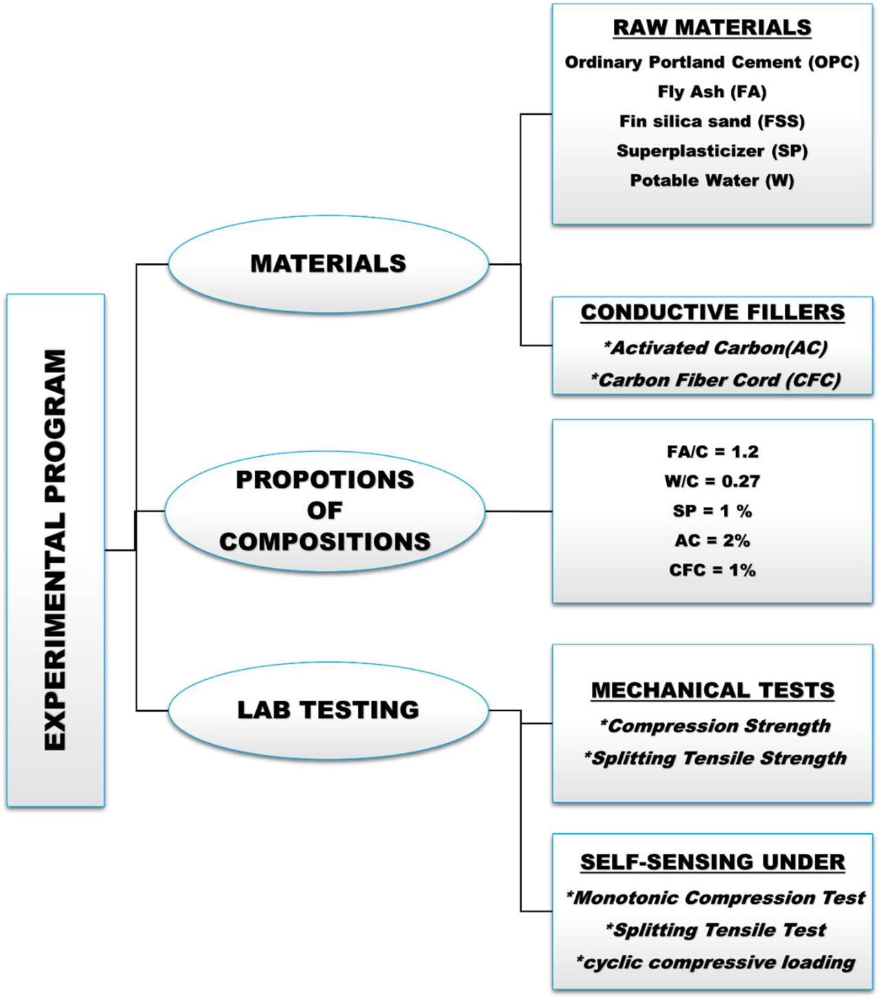
Figure 2:
Flowchart of the experimental work
2.1. Materials
The primary binder used in this study was ASTM Type I ordinary Portland cement (OPC), as specified in ASTM-C150 (2007). In alignment with the ECC matrix, the matrix compositions incorporated class F fly ash (FA), conforming to the ASTM-C618 (2014) standard. Fine silica sand (FSS), acting as the fine aggregate phase, exhibited a particle size range of 0–250 μm, a specific gravity of 2.6, and a water absorption capacity of 0.3% and was included in the mortars. To achieve optimal fresh-state properties, potable water and superplasticizer (SP) ViscoCrete®-5930 (2015) were employed, in accordance with ASTM-C494/C494M (2019) – Type F, with a density of 1.095 kg/L. Granular activated carbon (AC), sourced from the local market, was incorporated to enhance the electrical responsiveness of ECC mortars. This material is derived from the combustion of coconut shells and finds various applications, particularly in the electrical industry, due to its high carbon content. The density of the activated carbon ranged from 0.42 to 0.55 g/cm3, with particle sizes varying from 1 to 2.5 mm. The AC conditioning system utilized in this investigation is referenced in (Kaarela et al., 2021). Emphasizing the cost-effectiveness of activated carbon is crucial, particularly when compared to the costs of carbon nanomaterials. The cost of acquiring AC ranged from 5 to 10 cents/gram, while the cost of purchasing carbon nanomaterials, such as multi-walled carbon nanotubes and graphene nanosheets, ranged from 5 to 10 dollars/gram. Therefore, AC is significantly more economical than carbon-based nanoconductors. Meanwhile, carbon fibre cord (CFC), commercially known as SikaWrap® FX-50 C, was utilized as a fibre to enhance both mechanical and electrical properties. SikaWrap® FX-50 C is a unidirectional carbon fibre cord specifically designed for structural reinforcement. It features a dry fibre density of 1.82 g/cm3, a minimum dry fibre cross-section of 28 mm2, and a minimum mass of 50 g/m2. The material exhibits a dry fibre tensile strength of 4000 N/m2, a dry fibre modulus of elasticity of 240 kN/m2, and a dry fibre elongation at break of at least 1.60% (FX, 2017; SikaWrap®FX-50C, 2020). Table 1 outlines the physical and chemical properties of the raw materials. It details the chemical parameters of activated carbon, while Table 2 presents the physical characteristics supplied by the manufacturer. Figure 3 includes images captured by both the video camera and the scanning electron microscope (SEM) for each substance. Figures 4 and 5 show the Energy-Dispersive Spectroscopy (EDS) analysis for both the activated carbon and carbon fibre cord. Regarding AC, the SEM image (1000×, 30 kV) showed a highly complex rough surface with micro- and mesoporous features and irregular stacked layers, which corresponds to the structure of AC subjected to thermal/chemical activation processes. The porous nature and fine voids increase the effective surface area—an essential property for pollutant absorption or for improving particle dispersion within cement matrices. The EDS spectrum shows a dominance of carbon (~90 wt.%) with the presence of oxygen (~10 wt.%), indicating the presence of surface oxygen groups (−OH, −COOH, C=O) or surface moisture absorption resulting from the activation process. The presence of oxygen leads to better chemical interactions with the matrix binders (improving chemical adhesion), but it may slightly reduce the electrical conductivity compared to a more graphitic/graphene-like carbon form. As for the analysis of CFC, an SEM image (1,000×, 30 kV) shows regular longitudinal fibres with longitudinal striations typical of manufactured carbon fibres after the carbonization stage; the surface is smooth and uniform, with no clear pores or significant cracks. The quantitative EDS analysis confirms a higher carbon purity than activated carbon (≈94.5 wt.% C) and a decrease in oxygen (~5.5 wt.%), indicating a more graphitic and less functionalized surface. This means higher electrical conductivity and better mechanical durability. The presence of a small amount of oxygen may be the result of limited surface exposure or a sizing layer used in manufacturing.
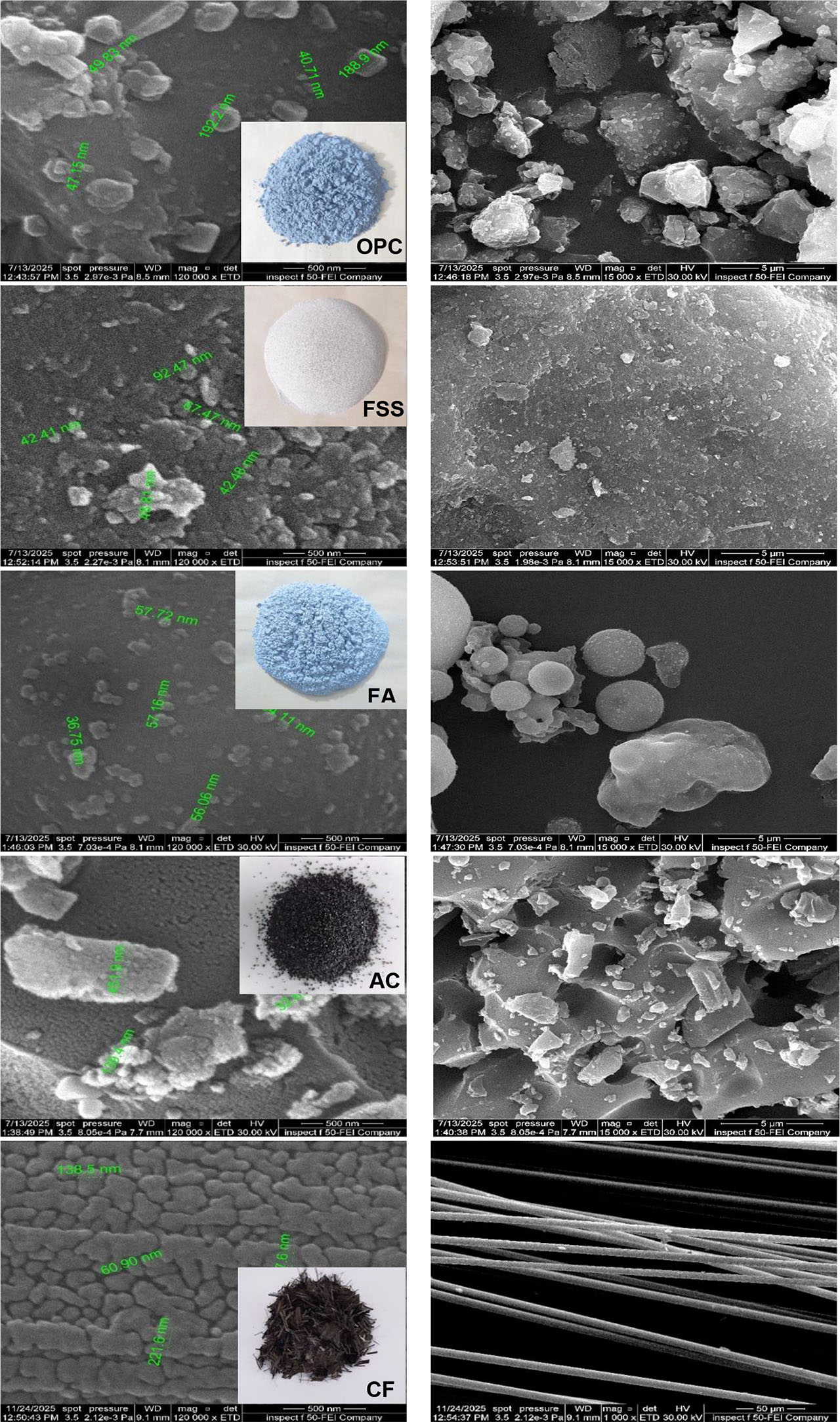
Figure 3:
Digital picture of the base and conductive materials, with FESEM images of each material, Nanoscale on the left and microscale on the right
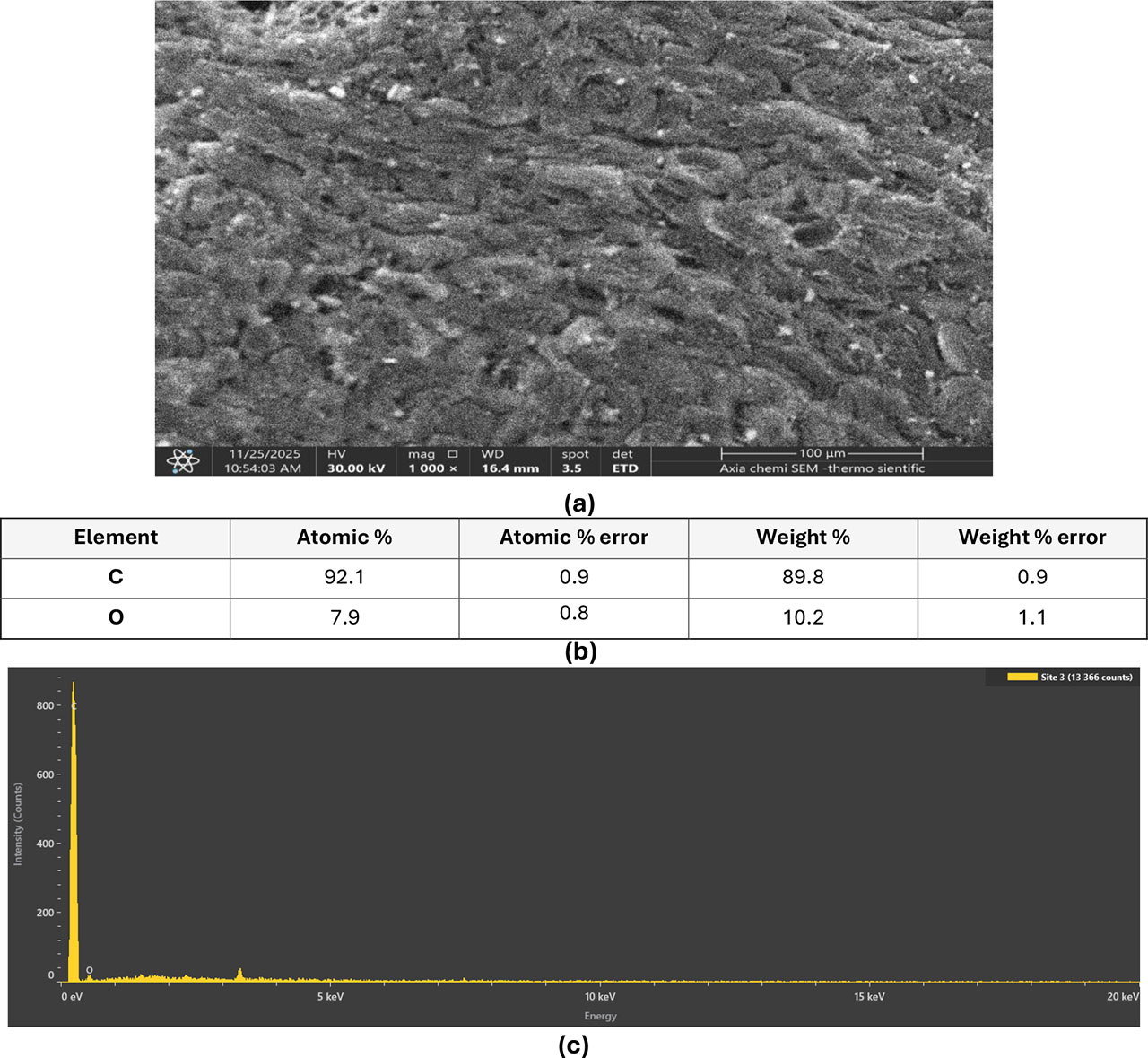
Figure 4:
EDS analysis of AC: (a) SEM image [1000× magnification; 30 kV]. (b) Quantitative EDS analysis [weight percentage]. (c) Corresponding EDS spectrum
2.2. Mixtures Preparation and Proportions
According to literature investigations (Abdullah et al., 2022; Abdullah et al., 2023; Al-Dahawi et al., 2024; Yıldırım et al., 2020), typical mix ratios for conventional ECC matrices, referred to in the literature as ECC-M45, were adopted. The ratio of fly ash (FA) to Portland cement (PC) in the mortar matrix was 1.2, the water-to-cementitious-compounds (PC + FA) ratio was 0.27, and the sand-to-cementitious-compounds ratio was 0.36. A set of three hybrid ECC mortar matrices, each containing varying dosages of activated carbon (AC) and carbon fibre (CFC), was prepared. These were coded according to their respective hybrid AC and CFC ratios as AC0.67CFC1, AC1.33CFC0.67, and AC2CFC0.33. For clear comparison, a reference matrix without hybrid fillers was prepared and designated as the “control.” The application rates of AC and CFC were selected based on the authors’ previous experience (Abdullah et al., 2022; Abdullah et al., 2023; Al-Dahawi, Sarwary, et al., 2016). Mini-slump flow testing was conducted on the mixes produced in accordance with ASTM-C124-71 (1971) to ensure acceptable and consistent workability for the manufactured cementitious composites. The superplasticizer (SP) content varied due to the differing amounts of the two hybrid fillers, which were used to maintain consistent flow levels across all mix types. The SP content was set at 1% by weight of the cementitious composites for all manufactured hybrid matrices, regardless of concentration variations due to the presence of carbon fibres. The tested ratios for the AC0.67CFC1, AC1.33CFC0.67, and AC2CFC0.33 matrices were 80%, 85%, and 100%, respectively. All flow ratios remained within the plastic range (50–100%), demonstrating the suitability of the superplasticizer ratios selected for each mix type. Figure 6 displays the deformation levels of the matrices that underwent the mini-slump flow test. Table 3 presents the ratios utilized to prepare the smart matrices for hybrid ECC mortar.
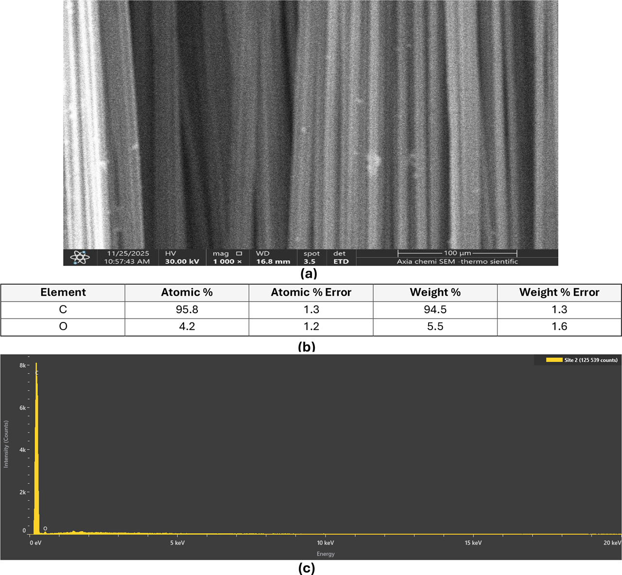
Figure 5:
EDS analysis of CFC: (a) SEM image [1000× magnification; 30 kV]. (b) Quantitative EDS analysis [weight percentage]. (c) Corresponding EDS spectrum
Table 1:
The chemical and physical characteristics of the raw ingredients [wt.%] utilized in the ECC matrix
| Oxide composition | OPC | FA | FSS | AC |
|---|---|---|---|---|
| CaO | 62.30 | 7.90 | 0.019 | 4.21 |
| SiO2 | 21.30 | 51.20 | 99.80 | 56.60 |
| Al2O3 | 3.77 | 17.03 | 0.061 | 25.30 |
| Fe2O3 | 4.69 | 6.65 | 0.022 | 4.64 |
| MgO | 3.71 | 2.23 | 0.01 | 0.78 |
| SO3 | 2.08 | 0.02 | - | 0.26 |
| Loss on ignition | 2.06 | 10.40 | 0.08 | 3.07 |
| Insoluble residue | 0.7 | - | - | - |
| Lime saturation factor | 0.93 | - | - | - |
| Physical properties | ||||
| Specific gravity | 3.11 | 2.13 | 2.60 | |
| Blaine fineness [cm2/g] | 3945 | 2689 | - | - |
Table 2:
Physical parameters of the AC used in ECC as supplied by the producer
| Raw material | Activated carbon with coconut |
|---|---|
| Mass density [g/cm3] | 0.42–0.55 |
| Ash content [%] | <10 |
| Hardness [%] | >92 |
| Moisture content, % | >5 |
| pH value | 9–11 |
| Iodine value [mg/g] | 900 |
| Surface area [cm2/g] | 1150 |
To complement the innovative system’s manufacturing approach, the carbon fibre rope was cut into small pieces, ranging from 10 to 15 mm, prior to the mixing process. This was to ensure uniform distribution and prevent dense fibre tangling when poured into the molds. Following this, the activated carbon granules were ground into a powder to enhance dispersion within the matrix and minimize the formation of large pores. After completing this step, the mixing phase commenced. To achieve optimal mechanical and electrical results, two approaches were utilized: the first involved dry mixing the raw materials with carbon fibres, while the second entailed wet mixing the activated carbon powder with water and a superplasticizer. A hand mixer set to 3,000 rpm was used to thoroughly combine the selected mix water with the superplasticizer and activated carbon for 15 minutes. Concurrently, the dry ingredients – comprising Portland cement, fly ash, sand, and carbon fibre composite—were mixed in a 20-liter mortar mixer for 10 minutes at 100 rpm. Subsequently, the wet mixture (water, superplasticizer, and activated carbon) was poured into the dry mixture (Portland cement, fly ash, sand, and carbon fibre composite) within 10 seconds while continuing to mix in the mortar mixer at 100 rpm. Mixing persisted at this speed for an additional 10 minutes. The mortar mixer speed was then increased to 300 rpm, and mixing continued for another 10 minutes to ensure uniform dispersion of all matrix components (Abdullah et al., 2022; Abdullah et al., 2023; Al-Dahawi, Öztürk, et al., 2016; Al-Dahawi et al., 2024). The fresh mixtures were then transferred to pre-oiled molds and stored under laboratory conditions for one full day at a relative humidity of 50 ± 5% and a temperature of 23 ± 2°C, with plastic covers placed over the sample surfaces. After 24 hours, the molds were opened, and the samples intended for mechanical and electrical testing were extracted. These samples were treated with water at 23 ± 2°C for an additional 26 days, followed by a full day of curing in an oven set at 60°C, resulting in a total age of 28 days. The primary aim of the self-sensing sample drying phase was to eliminate residual moisture, which could increase polarization and compromise the accuracy of electrical measurements, while simulating the harsh environmental conditions that concrete structures may face.
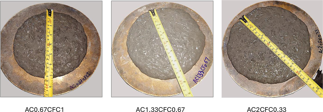
Figure 6:
The degrees of distortion in the matrices that were put through the mini-slump flow test
2.3. Tests
2.3.1. Mechanical Properties
Mechanical property evaluation included compressive strength and indirect tensile tests. To evaluate the compressive strength, fresh mixtures were cast into 5 cm3 cube molds and tested according to ASTM-C109/C109M (2005). A load was applied at a rate of 0.9 kN/s using a compression machine with a maximum load capacity of 3000 kN (Abdullah et al., 2022; Abdullah et al., 2023; Al-Dahawi et al., 2024). Three cube specimens were tested to evaluate the compressive strength of each mix at 28 days of age. Electrodes were embedded within the specimens for intrinsic sensing purposes. Compressive strength was evaluated by subjecting the specimen to two orientations, parallel and perpendicular to the embedded electrodes, during which intrinsic sensing measurements were also recorded (Figure 7a).
To perform the splitting tensile strength, innovative mixtures were poured into 5 cm3 cube molds and assessed according to ASTM-C496–96 (2017). The cube specimens were placed between two square bars, each measuring 10 cm in length, 1 cm in width, and 1 cm in height. Three cube specimens were tested to determine the splitting tensile strength of each matrix at 28 days of curing. Mechanical and self-sensing data were collected simultaneously using electrodes embedded in the samples (Figure 7b).
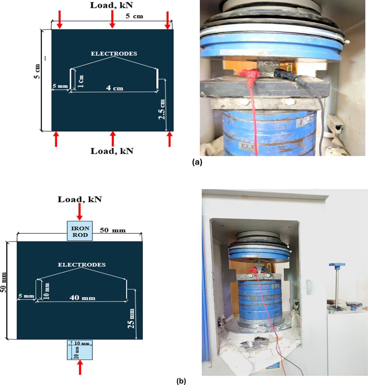
Figure 7:
Geometric design of specimens and mechanical and self-sensing setup: a) uniaxial compression; b) splitting tension
2.3.2. Self-sensing Properties
The self-sensing capability of intelligent ECC mortars was assessed by embedding tin electrodes at specific locations within cubic specimens (Figure 7). Experiments were conducted under uniaxial compression in various orientations relative to the embedded electrodes, as well as under splitting tension and cyclic compression loading conditions. The purpose of cyclic compression is to replicate the real-time behaviour of structures such as rigid pavements in situ. These structures undergo repetitive loading and unloading cycles influenced by factors such as vehicle movement, machinery vibrations, environmental conditions, and other variable live loads. During repetitive cyclic loading, the applied load level (25 kN) remained within the specimens’ elastic range, which is approximately one-third of the ultimate compressive strength determined from preliminary tests on three specimens. All tests were performed on specimens that were 28 days old, with each specimen undergoing three consecutive loading-unloading cycles in a parallel configuration, consistent with the other loading conditions. Electrical measurements were taken using the tin electrodes embedded in the specimens while under load. The cubes subjected to compression were fitted with two thin tin strips (70 × 10 × 0.1 mm), which exhibited a resistance ranging from 0.1 to 0.3 ohm (Ω) and were positioned symmetrically at a distance of 5 mm from the edges (Figure 7a). For splitting tensile tests, the same monotonic compression test setup was used (Figure 7b), following methodologies established in previous research (Abdullah et al., 2022; Abdullah et al., 2023; Al-Dahawi et al., 2024; Azhari & Banthia, 2012). A multimeter (Pro’sKit MT-1820 DC) was used to measure the electrical resistance of each specimen by connecting it to the embedded electrodes and recording the data through a computer interface. It is much easier to measure DC electrical resistance than AC resistance, which improves it for use in the field (Birgin et al., 2023; Chung, 2023). The variations in resistance relative to the applied load were transformed into fractional changes in electrical resistance (FCER) values using Equation 1, which indicates the material’s capacity for damage sensing.
Where:
RL - the electrical resistance under a specific load,
RO - the initial resistance,
FCER - the fractional change in electrical resistance.
To make sure the measurements were accurate, each sample was separated from the testing machine by placing wooden sheets between the sample surfaces and the loading heads, which kept them from touching the metal plates and reduced any possible signal interference.
3. Results and Discussion
This section discusses the results of this work on smart functional composites and control composites after 28 days, focusing on their durability and electrical properties. Table 4 presents a summary comparing all the mixture designs for both mechanical and sensing performance metrics.
Table 4:
Summary of average values of mechanical and self-sensing performance metrics for all mixture designs
| No. | Mixture ID | Mechanical properties | Self-sensing properties | |||||
|---|---|---|---|---|---|---|---|---|
| Compression [MPa] | Splitting tension [MPa] | FCER [% under compression] | FCER [% under splitting tension] | FCER [% under cyclic compression loading] | ||||
| Parallel | Perpendicular | parallel | Perpendicular | |||||
| 1 | Control | 61 | 69 | 2.6 | 112.07 | −48.1 | 166.2 | - |
| 2 | AC0.67CFC1 | 84.2 | 67.7 | 7 | −14.88 | −89.27 | 33.68 | −273.4 |
| 3 | AC1.33CFC0.67 | 53.6 | 51.8 | 5.5 | −73.96 | −53.42 | 6.5 | −18.3 |
| 4 | AC2CFC0.33 | 78.4 | 80 | 4.3 | −35.11 | −70.92 | 14 | −20.8 |
3.1. Mechanical Properties
3.1.1. Compressive Strength
Figure 8 displays the average 28-day compressive strength values for cubic specimens tested in both parallel and perpendicular configurations with the electrodes. The average compressive strength results for AC0.67CFC1, AC1.33CFC0.67, and AC2CFC0.33 specimens in the parallel direction were 84.2, 53.6, and 78.4 MPa, while the results were 67.7, 51.8, and 80 MPa when the loading was applied perpendicular to the electrodes. The results indicate an inverse relationship between compressive strength and the AC and CFC contents of the blends, regardless of electrode orientation. This trend aligns with previous findings (Frías et al., 2012; Frías et al., 2018; Justo-Reinoso et al., 2018; Na et al., 2021), suggesting that lower AC concentrations and higher fibre contents lead to increased strengths. Compared to the control samples, matrices enriched with the lowest dose of AC and the highest amount of CFC, as well as those with the highest concentration of AC and the lowest dose of CFC, showed significant improvements in compressive strength in both configurations. In contrast, the matrix with the intermediate dose of both conductive fillers exhibited a notable decrease in average compressive strength values in both the parallel and perpendicular settings compared to the control and smart matrices. The percentage increases for AC0.67CFC1 and AC2CFC0.33 were approximately 38% and 28%, respectively. Such an increase in enhancement is largely attributed to the continuous hydration process, which increases the density of the cementitious matrix. Depending on the type of filler, this can enhance strength across all mixes (Frías et al., 2012; Yıldırım et al., 2020). AC has demonstrated high pozzolanic activity in AC/Ca(OH)2 systems, with 80–90% lime consumption occurring between 28 and 90 days (Frías et al., 2011), explaining the high compressive strength values at 28 days in this study. Al-Qaessi and Abu-Farah (2010) found that incorporating 0.5% AC into cement mortar increases strength under load due to AC’s large surface area. However, increasing the AC dosage beyond optimal levels can reduce compressive strength, as the highly purified form of AC—with minimal impurities—may interfere with hydration. This trend is corroborated by other studies (Ball et al., 2022; Chin et al., 2020; Dinesh, Suji, Pichumani, et al., 2023). The observed improvement in compressive strength is linked to the increased density of the AC-produced matrices, resulting from the careful selection of dosages. Additionally, the rough surface of AC enhances the bonding of matrix components in the interfacial transition zone (ITZ), allowing hydration products to fill the pores created by the addition of AC at these dosages. But as the concentration of AC goes up, so does the porosity. This phenomenon means that the gel can’t fill all the pores, which makes the density lower and the compressive strength lower (Chin et al., 2020; Gupta et al., 2018). This aspect is where CFC contributes, working synergistically with AC powder through crack bridging, which inhibits crack growth under stress, particularly at high AC dosages that increase pore size and promote the growth of microcracks in the matrix microstructure, which CFC bridges and prevents from developing (Al-Dahawi, Sarwary, et al., 2016; Al-Dahawi et al., 2024). The behaviour of the AC1.33CFC0.67 matrix was markedly different from that of all other blends, including the control blends, contrary to the previously stated conclusion. The hybrid filler concentrations may have adversely impacted the synergistic behaviour of the fillers within the matrix. As noted earlier, increasing the amount of AC leads to a reduction in compressive strength. The differences observed were significant, approximately 14% in the parallel direction and 33% in the vertical direction, indicating that the CFC dosage was also inappropriate. Additionally, the fibre density may have caused tangling, clumping, and irregular dispersion, contributing to this decrease in strength.
There were no significant differences between the average stress values for the vertical and parallel configurations. The results presented in Figure 8 are intriguing and distinctive compared to previous studies that utilized expensive nanofillers, often in larger quantities, and were reinforced with fibers that may have enhanced the conductive network due to their nanocoating. However, the compressive strength values of the matrices in those studies (Parvaneh & Khiabani, 2018; Sedaghatdoost & Behfarnia, 2018) did not reach the same levels reported in this paper. This feature provides a carefully designed matrix and a substantial opportunity to emerge as a highly suitable matrix for mechanical applications. The findings of this study align closely with those of a prior investigation conducted by (Wang & Aslani, 2021; Wang et al., 2022). In that study, it was determined that the highest concentration of carbon fibre (0.7 wt.%) combined with the lowest concentration of activated carbon (0.25 wt.%) led to a 25% increase in compressive strength compared to the reference carbon fibre-reinforced matrix. This suggests that activated carbon significantly contributes to enhancing the performance of carbon fibre. However, in this current investigation, the compressive strength achieved was 84 MPa, which is higher than the maximum compressive strength reported in (Wang & Aslani, 2021) research, which did not exceed 50 MPa.
A study was conducted to ensure a fair comparison using an identical reference mixture, followed by a standardized evaluation of compressive strength. Smart materials were made by incorporating carbon nanotubes (CNT) at a concentration of 0.5 wt.%, reinforced once with polyvinyl alcohol (PVA) fibers and once with nylon fibers (NF) at a fixed dosage of 2 vol.% each, achieving a maximum compressive strength of 71.2 and 72.3 MPa, respectively (Ahmed et al., 2025). These results are lower than the documented compressive strength values in this study, which reached 84.2 MPa, at the same curing age of 28 days. This study demonstrated the synergistic effectiveness of activated carbon with carbon fibre rope in improving the cost-effectiveness and structural safety of ECC matrices.
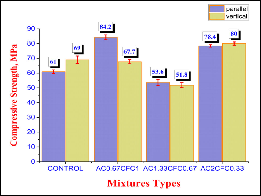
Figure 8:
Compressive strength results of both control and smart mixes at 28 days of age
3.1.2. Splitting Tensile Test
Figure 9 illustrates the variation in splitting tensile strength after 28 days for both the control blend and the smart hybrid blend composed of CFC and AC. The splitting tensile strengths of the matrices AC0.67CFC1, AC1.33CFC0.67, and AC2CFC0.33 were measured at 7, 5.5, and 4.3 MPa, respectively. The percentage gains for these innovative hybrid filler matrices were substantial compared to the control samples. The AC0.67CFC1 matrix demonstrated a 169% improvement. The strength increases for the AC1.33CFC0.67 matrix was 111%, while the AC2CFC0.33 matrix exhibited a 65% enhancement. The observed trends in splitting strength values align well with the behaviour of compressive strength. It is evident that the synergistic effect of the hybrid fillers within the same matrix contributes to improved strength under this loading scenario. For instance, (Dinesh, Suji, Pichumani, et al., 2023) reported that activated carbon could enhance tensile strength by 25% to 60%. The splitting tensile strength could rise from 2.45 MPa to 3.05 MPa as the AC concentration increased from 0% to 75% (Tran-SET, 2020), which aligns with the findings of the current study at a dosage of 0.67% by weight. The splitting tensile strength of carbon fibre-reinforced composites increases over time. This improvement is due to the carbon fibre composite enhancing the tensile zone and significantly reducing deflection, which results in a marked increase in tensile strength within this matrix design (Al-Dahawi et al., 2024; Khalil & Abdulrazaq, 2011). In addition, carbon fibers, like any other fibre, enhance splitting tensile strength by absorbing load energy and raising the volumetric stress capacity of concrete even after cracking. This process enhances post-peak behaviour and bridges cracks, delaying their progression to failure. The integration of carbon fibre is essential for enhancing the interfacial transition zone (ITZ) in cementitious composites. This enhancement results in superior mechanical properties, including heightened hardness and modulus, by efficiently densifying the interfacial transition zone, reducing voids, and promoting a strong bond between the fibre and matrix. This improves load transfer, increases fracture toughness, and enhances crack resistance, leading to superior strength and durability (He & Yang, 2021). The irregular texture of activated carbon may enhance splitting tensile strength by reinforcing connections at microcracks between the aggregate and the cement paste. An examination of the surface roughness of activated carbon granules indicates that this rough surface significantly improves the adhesion of matrix components within the interface transition zone (ITZ). This roughness allows hydration products to infiltrate the pores created by the incorporation of activated carbon. As the concentration of activated carbon increases, porosity reaches a point where the gel can no longer fill all the pores. Consequently, such porosity results in a reduction in the density of the matrix, which in turn decreases the strength of the matrix (Chin et al., 2020; Gupta et al., 2018; Na et al., 2021). It is worth discussing the comparison of the tensile strength results in this paper, which focused on sustainability and cost in selecting fillers, with other literature whose matrices are made from very expensive nanofillers. For example, the tensile strength in this study, with a value of 7 MPa, exceeds the results presented in an investigation conducted by (Ahmed et al., 2025), which achieved tensile strengths of 5.2 MPa and 4.2 MPa for a multi-walled carbon nanotube matrix reinforced with polyvinyl alcohol and nylon fibres, respectively.
To highlight the importance of matrices made from sustainable, low-cost, and environmentally friendly fillers the results of this investigation obtained from the splitting tensile strength test were compared with the results presented in the literature (Ahmed et al., 2025), which used the same control matrix and were injected with carbon nanotubes (CNT) at a concentration of 0.5% by weight, reinforced once with polyvinyl alcohol (PVA) fibers and once again with nylon (NF) fibers at a fixed dosage of 2% by volume for each. The values of the splitting tensile strength for the two matrices, CNT0.5PVA2 and CNT0.5NF2, were 5.2 and 4.2 MPa, respectively, at 28 days of curing. At the same curing age, the matrices made from AC and CFC achieved a splitting tensile strength value of 7 MPa. The splitting tensile strength superiority ratios in this investigation compared to those mentioned in the literature (Ahmed et al., 2025) were 26% and 40% for the matrices CNT0.5PVA2 and CNT0.5NF2, respectively. This superiority takes into account the excellence and efficiency of the current matrices, which are considered low-cost, sustainable, and effective for the overall safety of concrete structures in various applications.
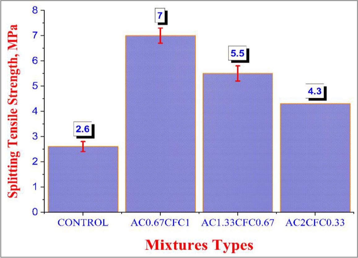
Figure 9:
Average splitting tensile strength results for hybrid matrices at 28 days
3.2. Self-sensing Behaviour
3.2.1. Under Uniaxial Compressive Loading
Figures 10 and 11 illustrate the capability of innovative Engineered Cementitious Composites (ECC) made with hybrid conductive fillers to self-sense damage due to uniaxial monotonic compressive loads applied in parallel and perpendicular directions, respectively. The fractional change in electrical resistance (FCER) serves as the fundamental basis for assessing the response of these smart composites to the applied load. Based on this concept and a careful analysis of Figures 10 and 11, it is important to clarify several aspects of their sensing behaviour. FCER values can be categorized as positive and negative, depending on their response pattern to applied stress and various factors related to the influence of the filler on the structural matrix. Positive FCER values indicate an increase in electrical resistance and a decrease in conductivity. This phenomenon can occur for several reasons, such as the formation of microcracks, disruption of conductive paths, debonding at the interface between the conductive fillers and the matrix, and the presence of tensile stress zones, particularly under the influence of indirect tensile stress or localized splitting (Yıldırım et al., 2020). Conversely, negative FCER values signify a reduction in electrical resistance and an increase in conductivity. These changes can happen for several reasons, including the closer proximity of conductive particles or electrodes (which shortens the electrical network paths), the closure of microcracks under stress, and the repair of defects that enhance conductivity (Al-Dahawi et al., 2024; Dinesh, Suji, et al., 2023b). Furthermore, applying a load improves the connectivity or tightness of the fibers within the conductive fibre-reinforced matrix, which contributes to a reduction in electrical resistance.
In Figure 10, the sensing behaviour of the hybrid smart mixes is clearly evident, showcasing negative FCER values, in contrast to the control mixes, which display positive sensing values in parallel electrode configurations. In conventional ECC mortars, changes in electrical resistance are anticipated due to the movement of water and ions within the pore network when subjected to an electric field (Ranade et al., 2014). The behaviour of the arrays in Figures 10b–d can be attributed to the formation of a conductive network, wherein the hybrid filler acts synergistically. Instead of the electrical network paths being disrupted under loading (as observed in the control mix, Figure 10a, the network paths within the matrix become shortened, and the defects caused by microcracks in the microstructure of the matrix are repaired, facilitating efficient electron transfer and smooth flow between the two electrodes of the sample. The synergistic effect of AC and CFC is crucial in explaining this behaviour, aligning with the findings of (Abdullah et al., 2023). Furthermore, the interfacial transition zone (ITZ) between the hybrid fillers and the matrix, as well as between the embedded electrodes and the matrix, directly influences the observed increase in conductivity. A reduced interfacial transition zone (ITZ) may lead to a more significant change in resistance when under load, which could enhance the piezoresistive effect and self-sensing capabilities (Nuruzzaman et al., 2023). At low doses of AC, it permits the gel to infiltrate the pores (Chin et al., 2020; Gupta et al., 2018), which weakens the network’s conductivity. As a result, it can be concluded that CFC enhances the network’s electrical conductivity through fibre-to-fibre and fibre-to-matrix interactions. At elevated concentrations of AC, the tunnelling phenomenon, coupled with the bridging effect of the carbon fibers, positively influences conductivity under loading. This explanation is relevant to the ITZ between the electrodes and the matrix interface. Despite the separation of the electrodes and their outward push, which is expected to raise the resistance under loading, this behaviour occurs because the molecules are brought closer together and the conductive network is shortened due to the synergistic effects of the fibers and particles. Additionally, the impacts of hydration products diminish due to the large pore sizes being compensated by the carbon fibers.
In Figure 11, all graphs show the conductivity behaviour, including the reference matrix, unlike Figure 10. This is primarily because the load applied to the sample in the vertical configuration stimulates the electrodes to converge inward, rather than pushing it outward as it does in the parallel configuration, which enhances the interfacial transition zone (ITZ) between both the electrode interface and the array, as well as among the components of the array itself (Xu et al., 2000). This argument is in addition to the justifications above for the increased conductivity and decreased electrical resistance under applied stress. The AC0.67CFC1 and AC1.33CFC0.67 matrices demonstrated an excellent and stable electrical response, achieving satisfactory FCER values in both parallel and vertical configurations. They exhibited a zero-point response under load, which is not observed in the AC2CFC0.33 matrix. This behaviour suggests that these matrices, particularly AC1.33CFC0.67, provide superior self-sensing performance under compressive loading. The influence of electrode orientation on the measured piezoresistive response is critical to understanding the contrasting FCER patterns observed in Figures 10 and 11. When the electrodes are placed in a parallel configuration (aligned with the direction of loading), the lateral expansion of the sample under compression tends to push the embedded electrodes outward, increasing the effective spacing between them. This deformation weakens the interfacial transition zone (ITZ) and promotes partial disruption of the conductive pathways, which explains the positive FCER values in the control matrix and the selective negative FCER value trends in hybrid mixtures where a more robust conductive network exists. Conversely, in the perpendicular (vertical) configuration, the applied compressive load forces the electrodes inward toward one another. This action densifies the ITZ along the measurement path and reduces the inter-electrode distance, thereby enhancing fibre-to-fibre and fibre-to-matrix contact. As a result, all mixtures—including the reference composite – exhibit consistent negative FCER values, indicating improved conductivity under compressive stress. This behaviour aligns with the known sensitivity of cementitious resistivity measurements to electrode–matrix contact pressure (Abedi et al., 2022; Cosoli et al., 2020). Figure 12 shows a schematic representation of the contrasting interactions between deformation and electrode in both configurations to demonstrate their effects on the evolution of the conductive paths during loading.
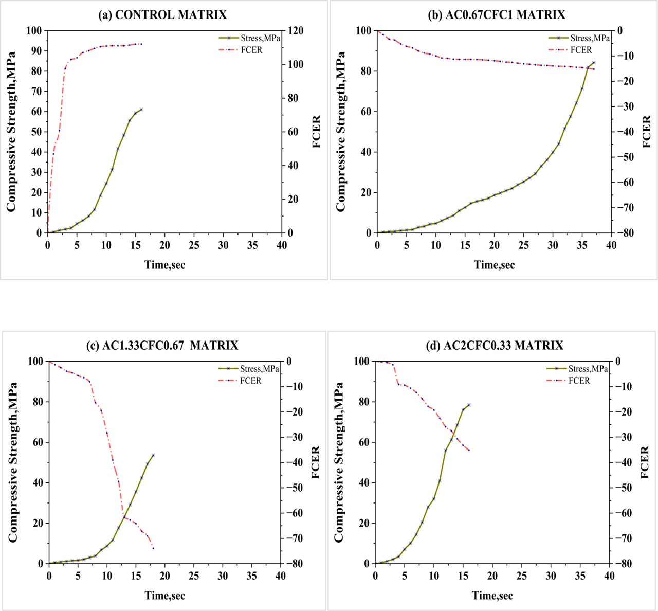
Figure 10:
Self-sensing response to monotonic compressive loads in parallel setup
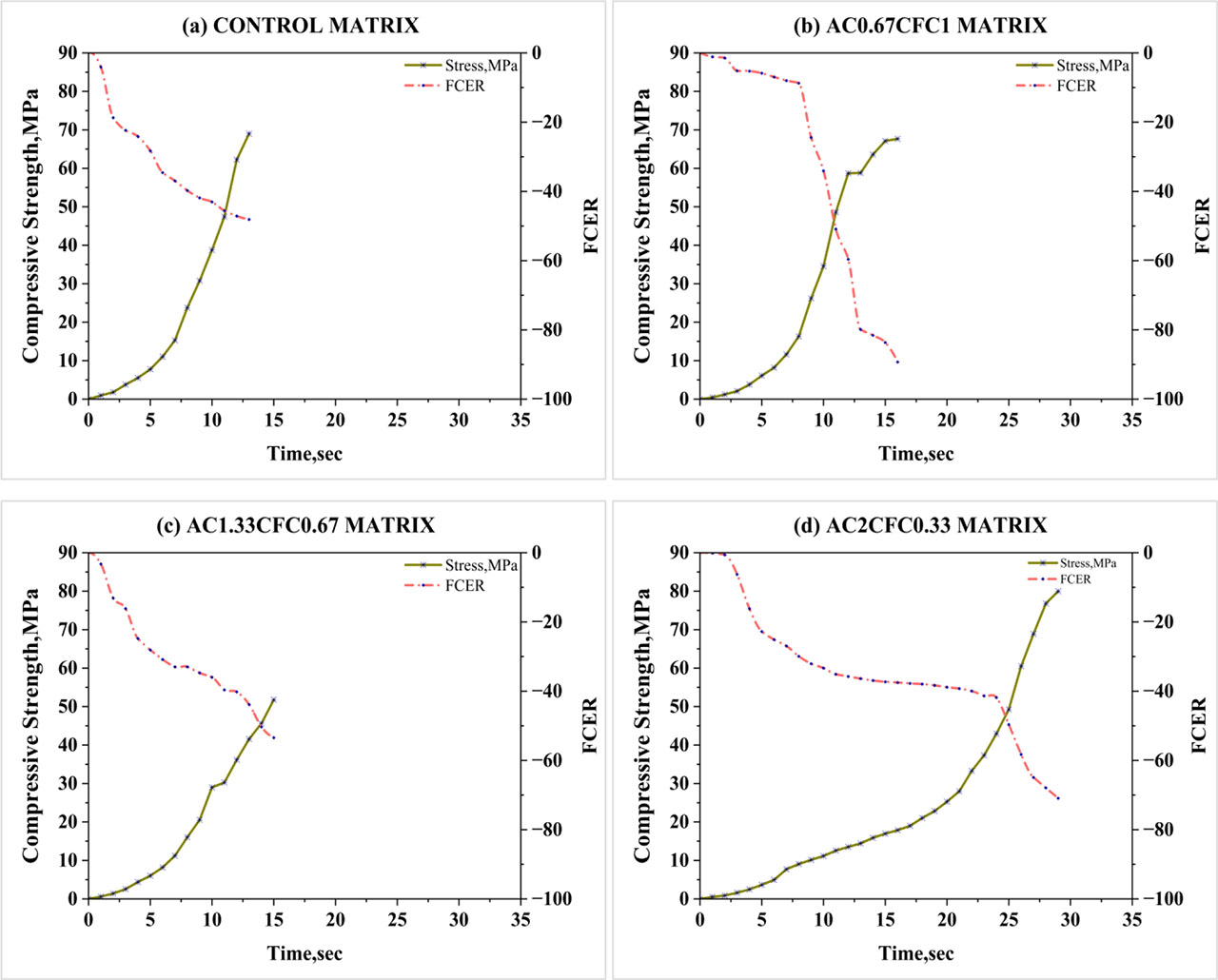
Figure 11:
Self-sensing response to monotonic compressive loads in vertical setup
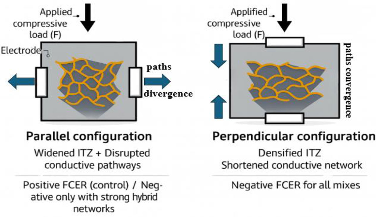
Figure 12:
The schematic representation illustrates the effect of electrode orientation – parallel versus perpendicular - under uniaxial compressive loading
3.2.2. Under Splitting Tensile Loading
Figure 13 provides an overview of the ability of the novel hybrid filler matrix to detect early damage caused by splitting tensile stress. While the sensing values vary, all matrices shown in Figures 13b–d exhibit a near-linear FCER response, with an increase starting immediately after the load is applied and remaining directly proportional to that load. A distinctive behaviour is noticeable in the AC0.67CFC1 array. In the elastic range, its response is linear and gradually increases with the load. However, there is a sudden spike in sensing values at the plastic range, which is the stage where the structure begins to collapse due to crack expansion until failure occurs. This characteristic makes the AC0.67CFC1 array particularly exceptional and suitable for use under splitting tensile stress, especially given its performance combined with the highest mechanical strength. This behaviour aligns with existing literature (Yıldırım et al., 2020), which indicates that a unique crack forms and gradually develops with increasing stress in samples subjected to splitting tensile stress. The observed improvement is attributed to several factors, such as the formation of microcracks, disruption of conductive paths, debonding at the interface between conductive fillers and the matrix, and the presence of tensile stress zones, especially under splitting tensile stress or localized cleavage. Optimal performance is closely linked to the careful selection of a mixture design based on the proposed dosage (Al-Dahawi et al., 2024). The synergistic effect between carbon fibers and activated carbon powder provides the matrices with the necessary sensitivity under splitting tensile loading. The high tensile strength of carbon fibers helps maintain a continuous electrical network within the matrix for as long as possible before failure (Shin et al., 2023), while the presence of activated carbon enhances electrical conductivity. It is likely that the interfacial transition zone (ITZ), which significantly improves the bonding strength of the components, directly influences the behaviour of matrices modified with varying concentrations of AC and CFC under this type of loading.
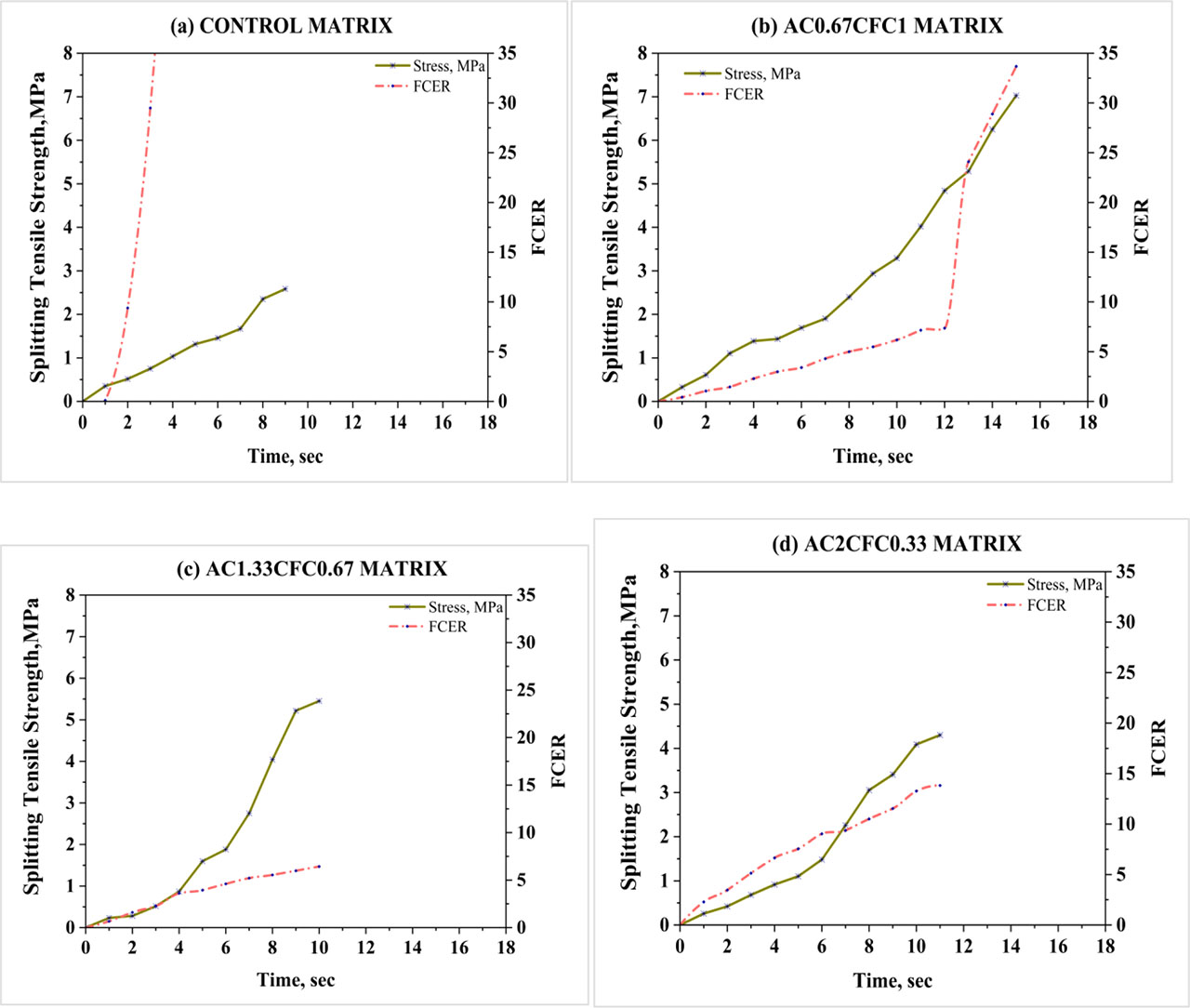
Figure 13:
Self-sensing response to splitting tensile loads
3.2.3. Under Cyclic Compressive Loading
As illustrated in Figure 14 (a, b, and c), all carbon-based hybrid filler-impregnated mortars exhibited distinct and consistent behaviour when subjected to cyclic compressive stress. A significant fibre conductivity enhancement ratio (FCER) was observed after loading, and this change was completely reversible upon unloading. Among the matrices evaluated, the AC0.67CFC1 matrix demonstrated outstanding performance, achieving an FCER of 250%, thus establishing it as the most effective sensing matrix in this paper. The FCER reflects the reversible reduction in resistivity observed after each loading cycle. This phenomenon can be attributed to the reversible repair of defects under compressive stress. As cyclic loading progresses, microstructural damage accumulates; however, during compression, internal flaws are partially closed or repaired, leading to a reduction in electrical resistance. The interfacial transition zone between fine aggregates and the cement matrix plays a vital role in facilitating this reversible defect repair (Cao et al., 2001). Moderate compressive stress aids in the closure of microcracks and internal defects, which enhances electrical conductivity by lowering resistance. Upon unloading, the structure undergoes partial recovery or repair of its microstructure, thereby reinforcing the reversibility of the sensing ability (Qiu et al., 2021; Wang et al., 2019).
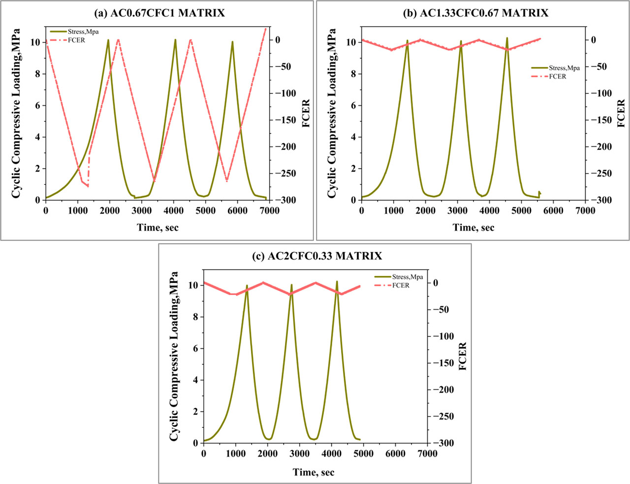
Figure 14:
The self-sensing ability of hybrid matrices under cyclic compression loading at 28 days
4. Conclusions
This research was conducted to develop an intelligent hybrid mortar for early damage detection by incorporating activated carbon (AC) and carbon fibre cord (CFC) as conductive fillers. The primary results are that the hybridization of AC and CFC markedly enhances material properties. Specifically, the AC0.67CFC1 matrix demonstrated superior mechanical strength under both compression and tension tests, surpassing all other matrices. Furthermore, all developed mortars exhibited consistent self-sensing behaviour; their conductivity increased under load and decreased upon unloading, showing excellent reversibility under cyclic conditions. Owing to its dual advantage of high mechanical strength and reliable self-sensing response, the AC0.67CFC1 mix is an optimal material for smart infrastructure applications, particularly for real-time traffic monitoring and load measurement.
Acknowledgment
The authors sincerely appreciate the collaboration of the civil engineering college laboratories at the University of Technology for their assistance in conducting this research.
Notes
[2] Contributed by Author Contributions
S. R. and R. D. conceived and designed the study, conducted the experiments, and collected the data. They also participated in manuscript drafting. All authors critically reviewed and approved the final version of the manuscript and agreed to be accountable for all aspects of the work.