

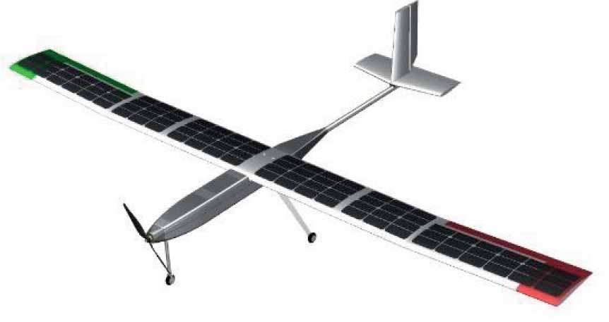
Figure 1.
Visualization of the AZ-5 UAV research platform
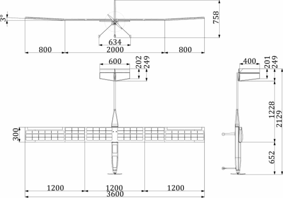
Figure 2.
Basic dimensions of the AZ-5 UAV research platform
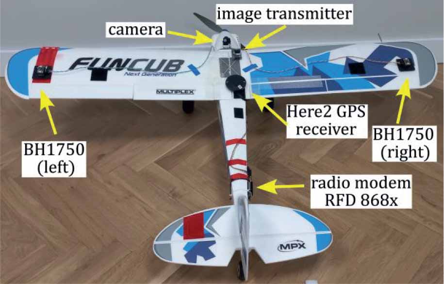
Figure 3.
Test platform used in the experiments
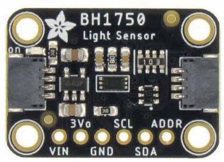
Figure 4.
BH1750 light sensor
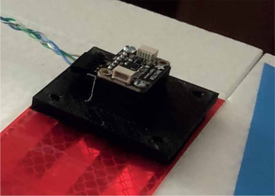
Figure 5.
Sensor mounted on the surface of the left wing
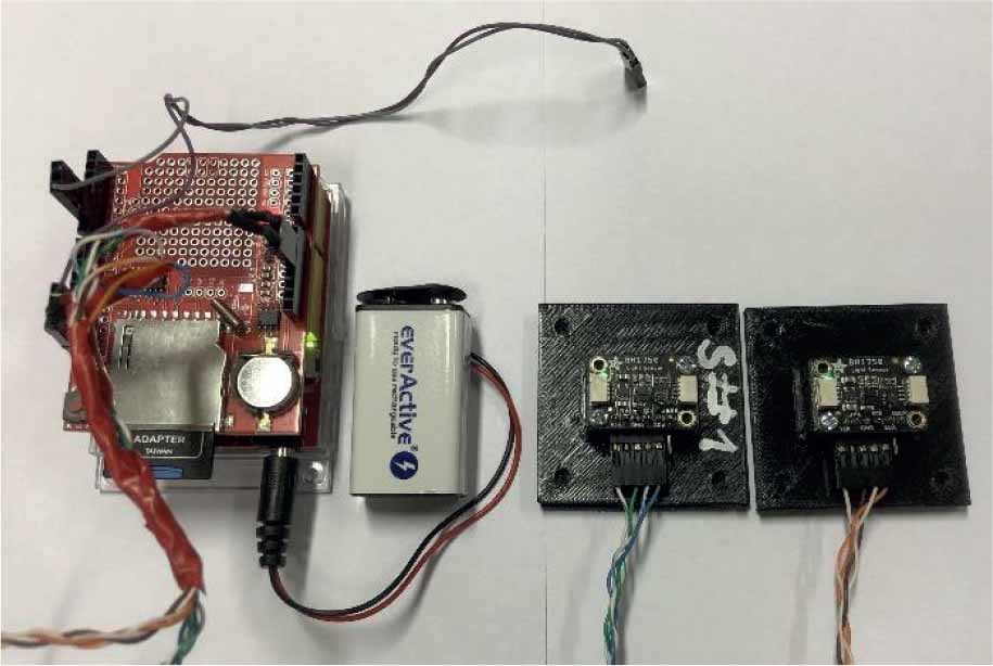
Figure 6.
Completed set of solar radiation measurement system
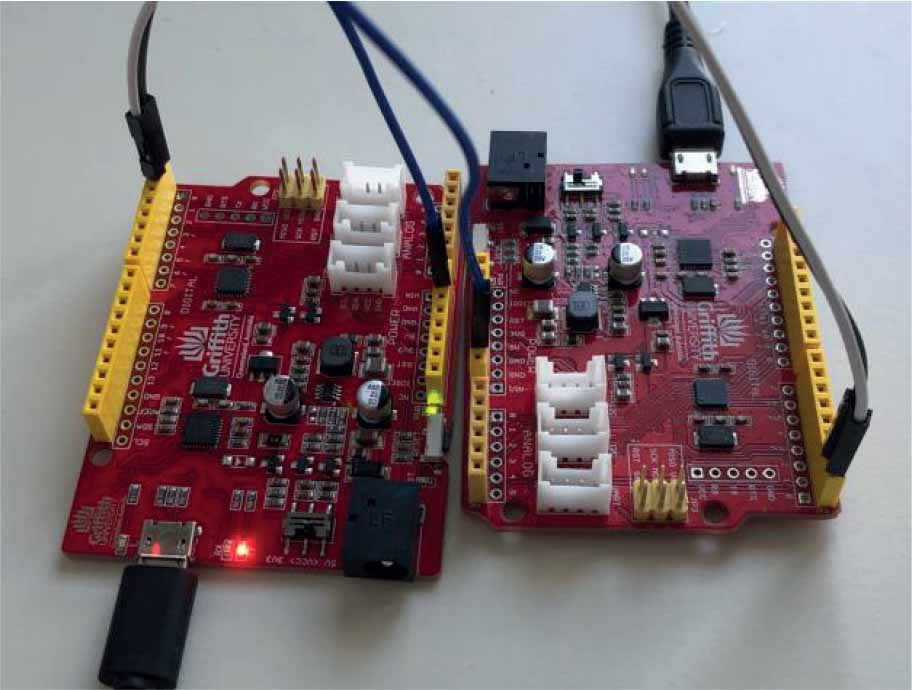
Figure 7.
Microcontroller protocol communication test
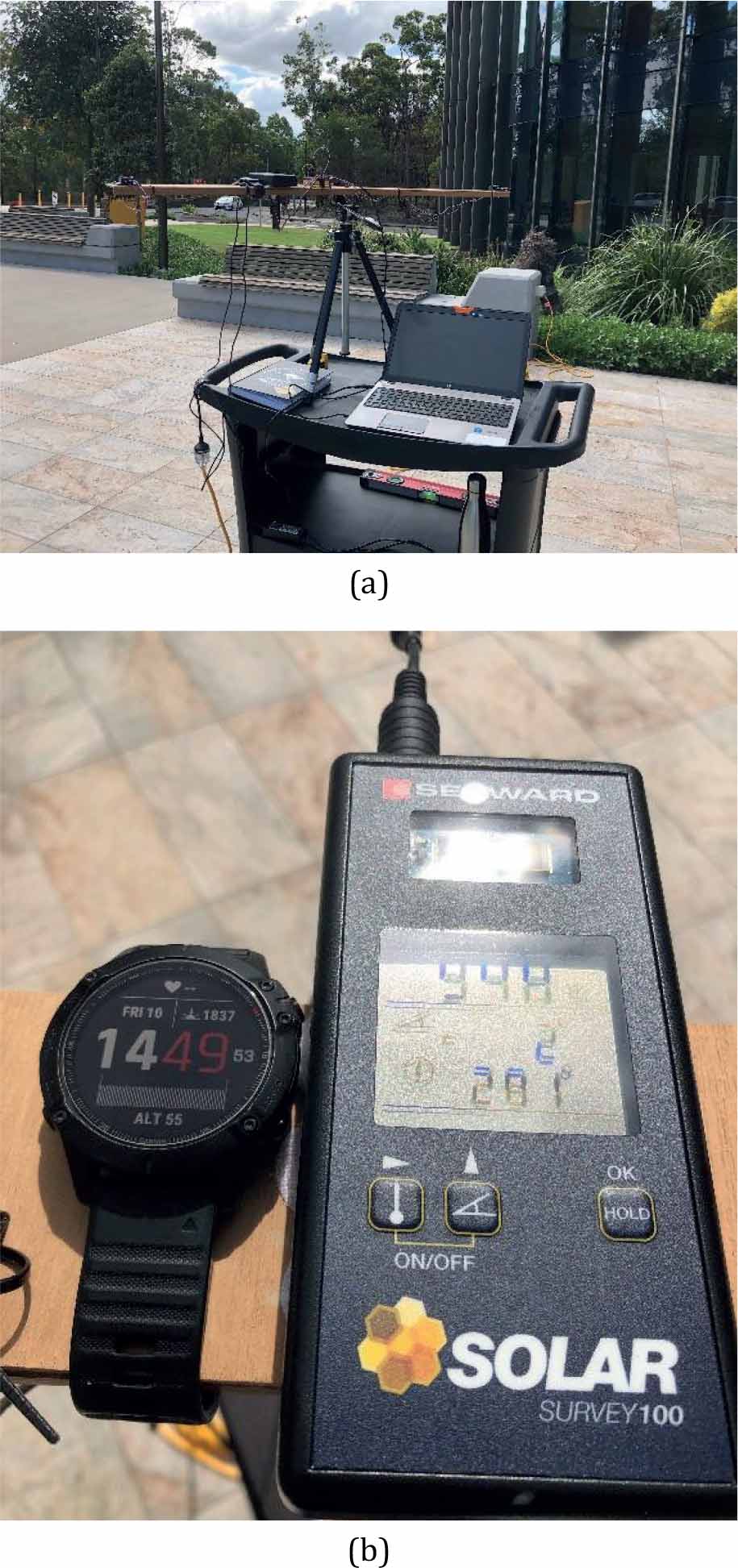
Figure 8.
(a) Stationary test stand during experiments in Brisbane (b) Solar Survey 100 irradiance meter
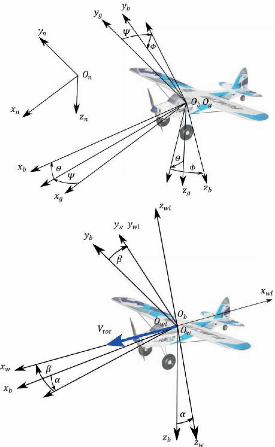
Figure 9.
Coordinate systems used in the model
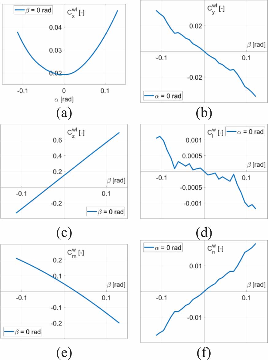
Figure 10.
Aerodynamic coefficients of the airplane (a) drag (b) side force (c) lift force (d) rolling moment (e) pitching moment (f) yawing moment
Table 1.
Stability and control derivatives of the Funcub plane
| Longitudinal | Value | Unit | Lateral–directional | Value | Unit |
|---|---|---|---|---|---|
| 0,01920 | – | 0 | – | ||
| 0,01653 | 1/rad | –0,26240 | 1/rad | ||
| 1,53900 | 1/rad2 | –0,07607 | 1/rad | ||
| 0,29927 | 1/rad | 0,22320 | 1/rad | ||
| 0,00989 | 1/rad | 0 | 1/rad | ||
| 0,14840 | – | 0,11450 | 1/rad | ||
| 4,22000 | 1/rad | 0 | – | ||
| 7,08930 | 1/rad | –0,00789 | 1/rad | ||
| 0,49847 | 1/rad | –0,46079 | 1/rad | ||
| 0,03794 | – | 0,10362 | 1/rad | ||
| –1,68900 | 1/rad | –0,14324 | 1/rad | ||
| –9,69450 | 1/rad | 0,01302 | 1/rad | ||
| –1,20320 | 1/rad | 0 | – | ||
| 0,14330 | 1/rad | ||||
| –0,02406 | 1/rad | ||||
| –0,10615 | 1/rad | ||||
| 0 | 1/rad | ||||
| –0,05460 | 1/rad |
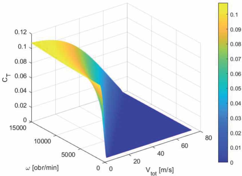
Figure 11.
Thrust coefficient
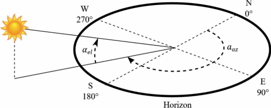
Figure 12.
Solar azimuth and elevation angles
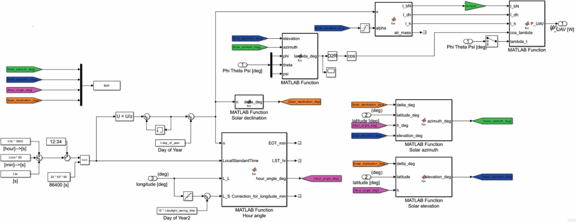
Figure 13.
Solar radiation model implemented in SIMULINK
Table 2.
Power consumption of system’s components
| Test case | Voltage [V] | Current [A] | Power [W] |
|---|---|---|---|
| Solar radiation measurement system | 9.11 | 0.075 | 0.683 |
| Avionics + propulsion (main motor off) | 12.40 | 0.575 | 7.130 |
| Avionics + propulsion (main motor on – at cruise RPM) | 9.55 | 29.460 | 281.343 |
| Avionics + propulsion (main motor on – maximum RPM) | 8.80 | 70.270 | 618.376 |
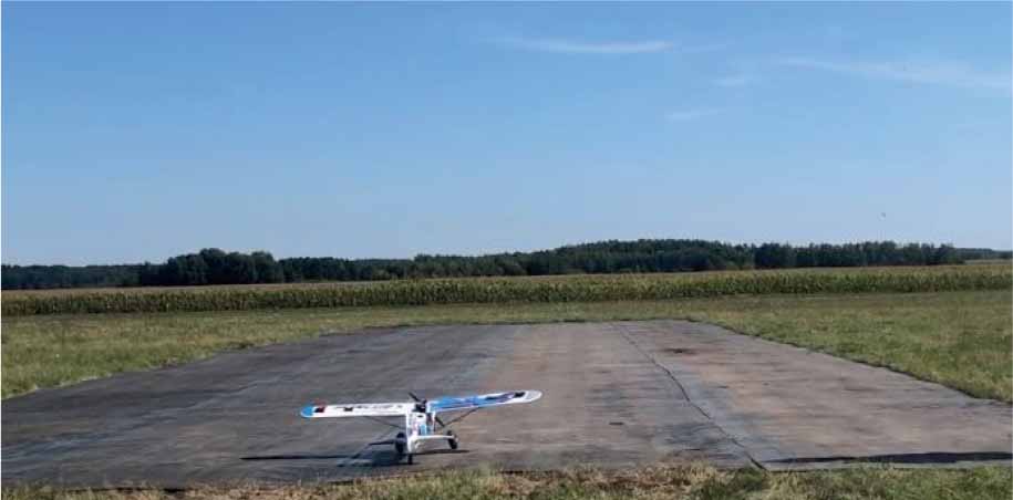
Figure 14.
Aircraft ready to start at the runway in Przasnysz airfield.
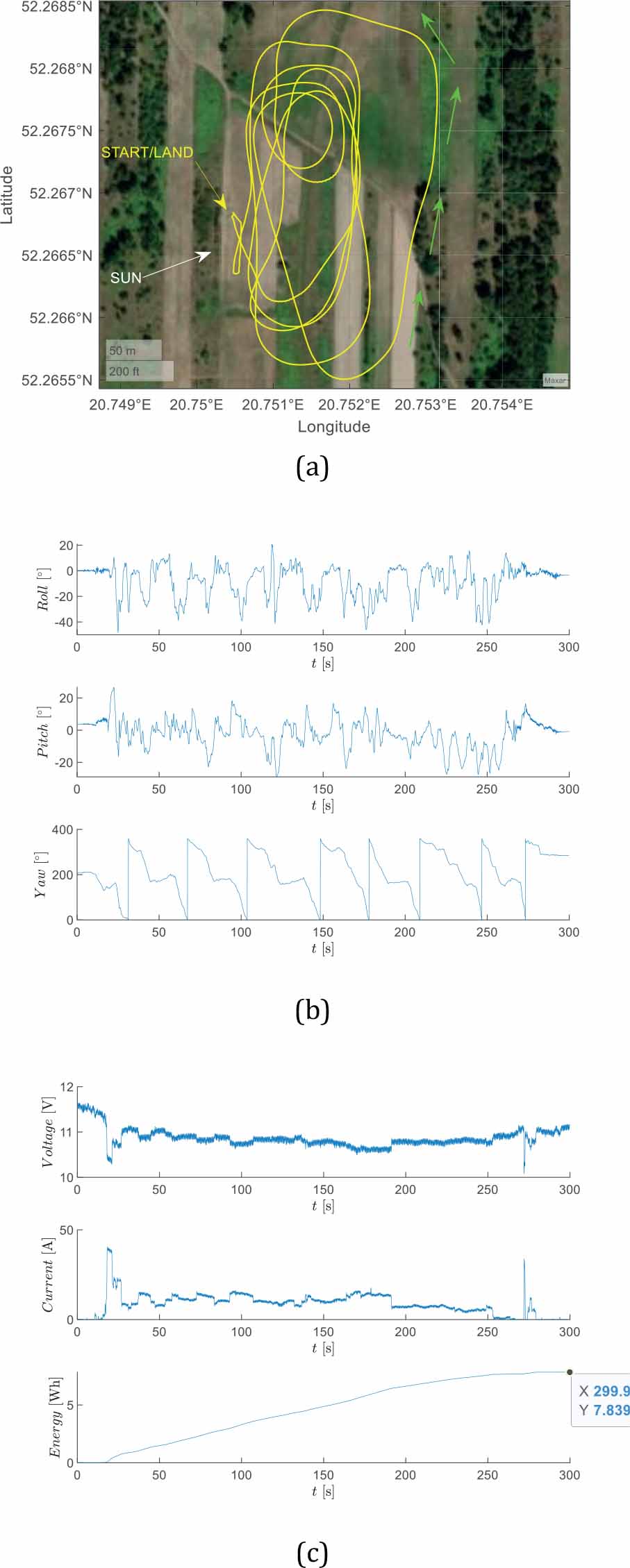
Figure 15.
Aircraft flight parameters (a) position (b) roll, pitch, yaw angles (c) battery voltage, current, and consumed energy (case 1)
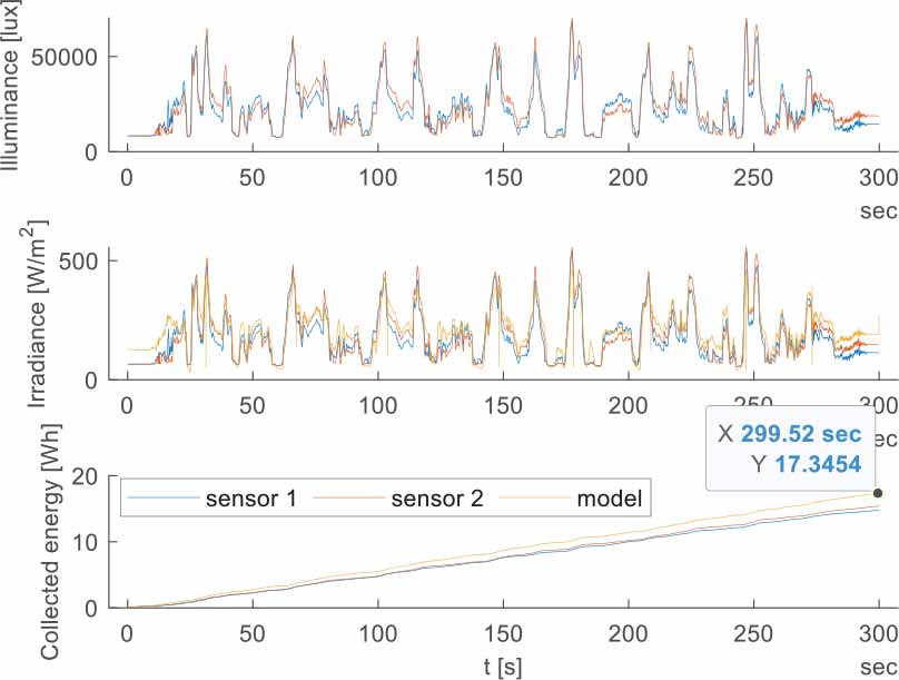
Figure 16.
Solar illuminance, radiation intensity, and energy (case 1)
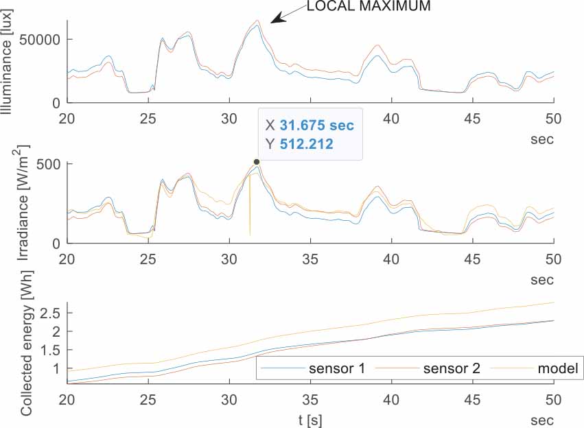
Figure 17.
Roll, pitch, yaw angles (case 1, enlarged view)
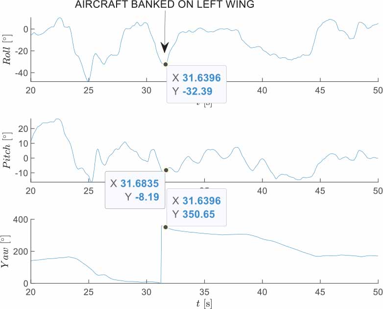
Figure 18.
Solar illuminance, radiation intensity, and energy (case 1, enlarged view)
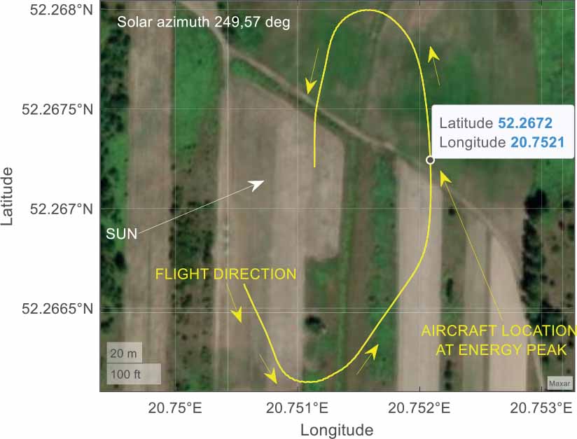
Figure 19.
Approximate aircraft location at energy peak (case 1, enlarged view)
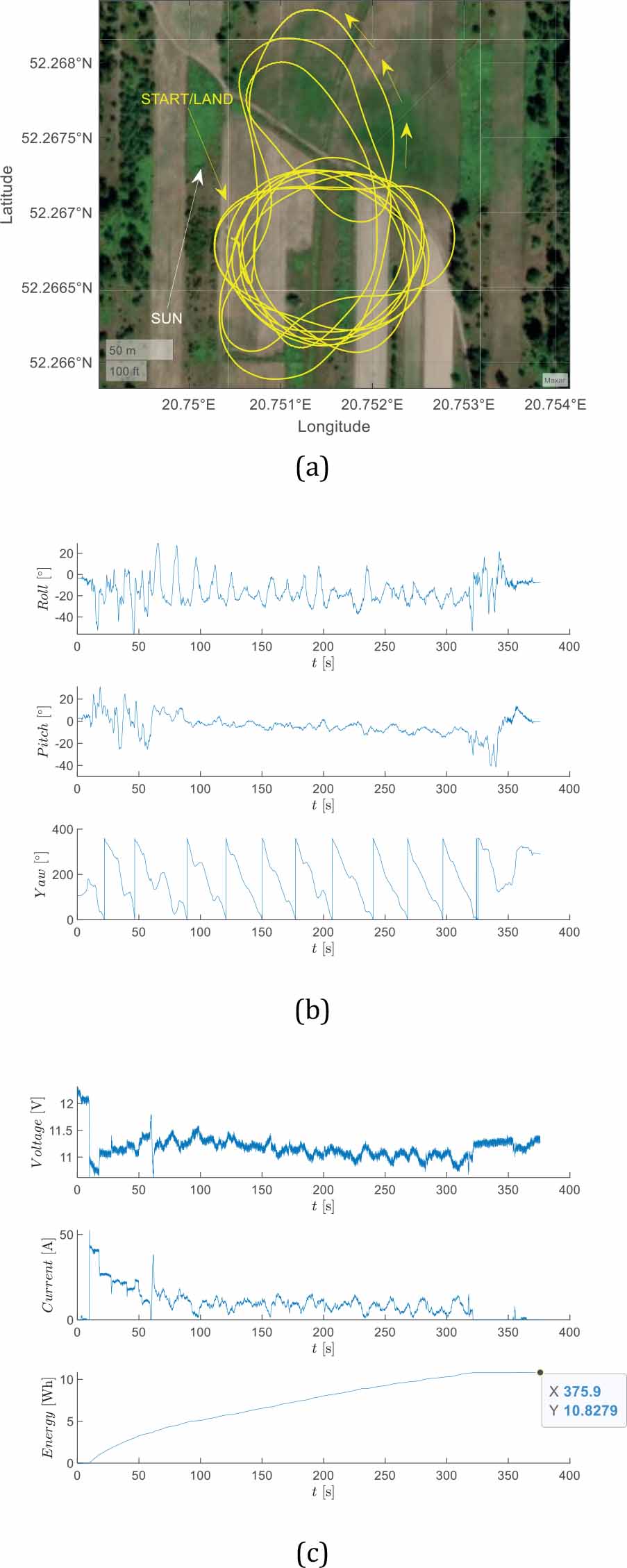
Figure 20.
Aircraft flight parameters (a) position (b) roll, pitch, yaw angles (c) battery voltage, current, and consumed energy (case 2)
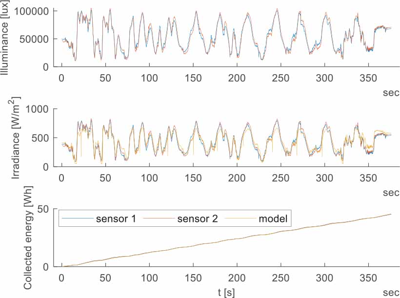
Figure 21.
Solar illuminance, radiation intensity, and energy (case 2)
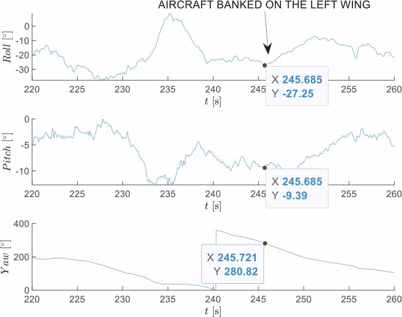
Figure 22.
Roll, pitch, yaw angles (case 2, enlarged view)
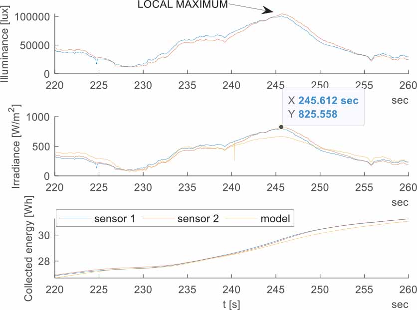
Figure 23.
Solar illuminance, radiation intensity, and energy (case 2, enlarged view)
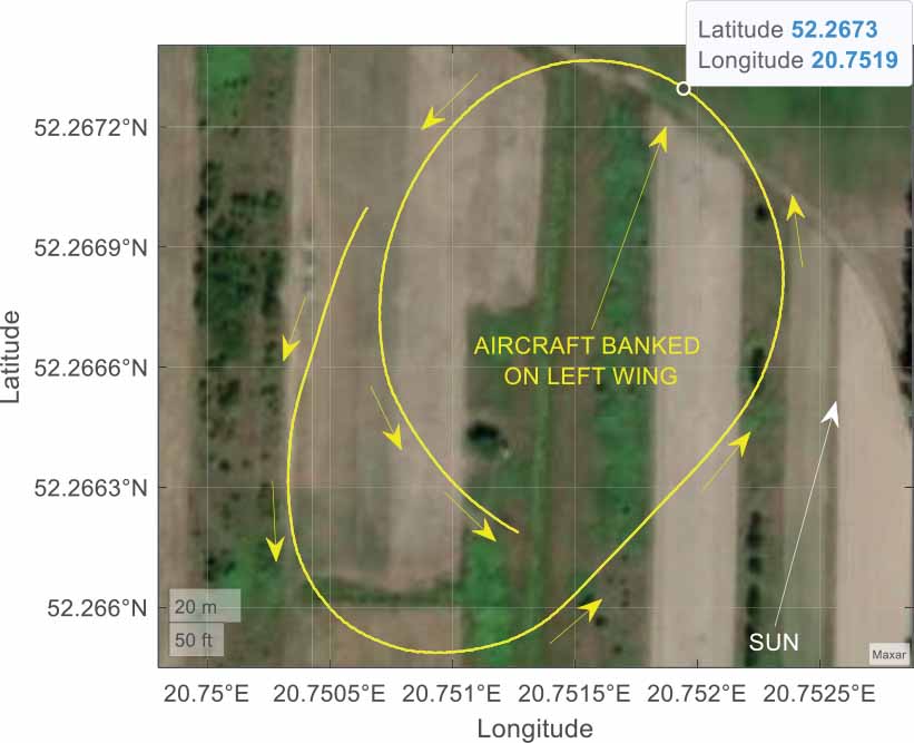
Figure 24.
Approximate aircraft location at energy peak (case 2, enlarged view)
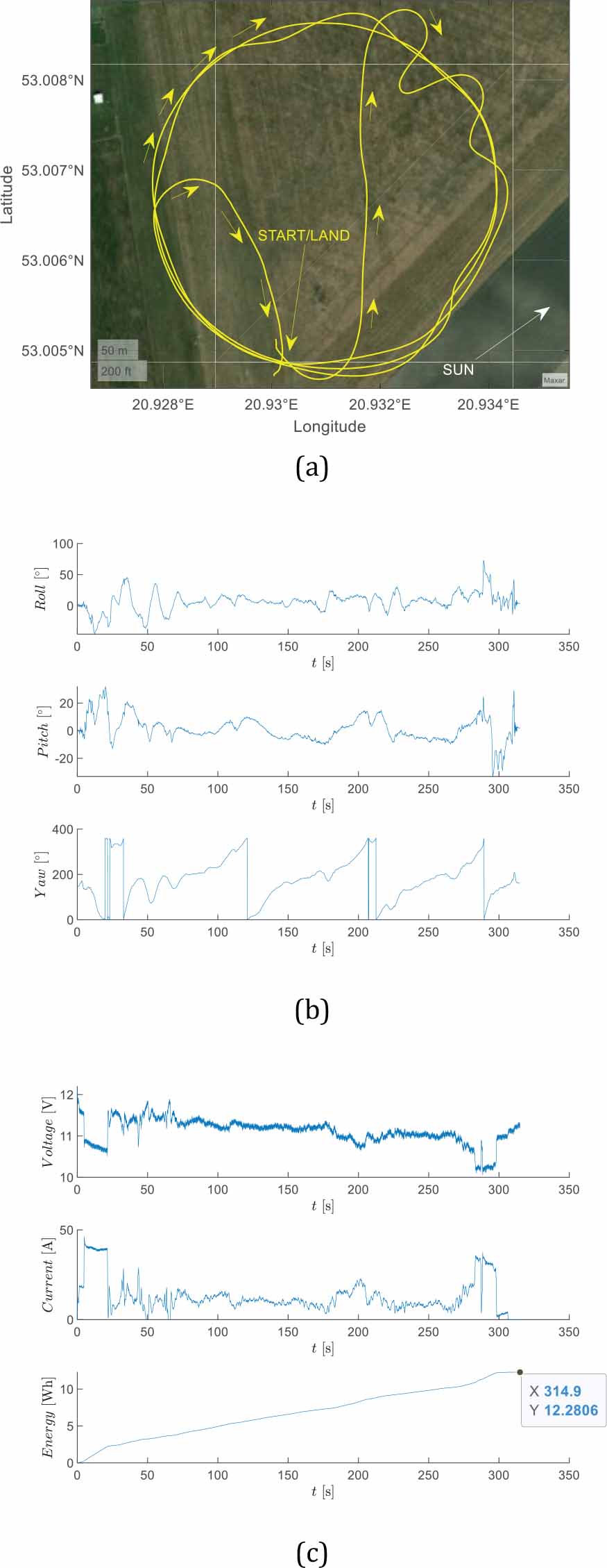
Figure 25.
Aircraft flight parameters (a) position (b) roll, pitch, yaw angles (c) battery voltage, current, and consumed energy (case 3)
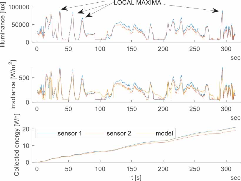
Figure 26.
Solar illuminance, radiation intensity, and energy (case 3)
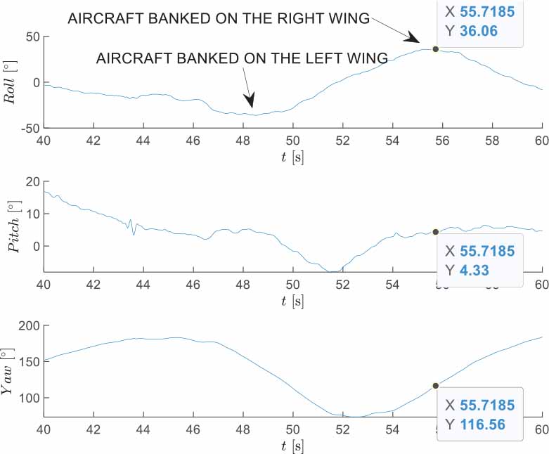
Figure 27.
Roll, pitch, yaw angles (case 3, enlarged view)
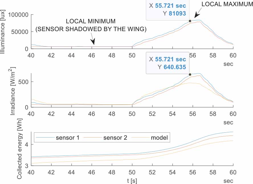
Figure 28.
Solar illuminance, radiation intensity, and energy (case 3, enlarged view)
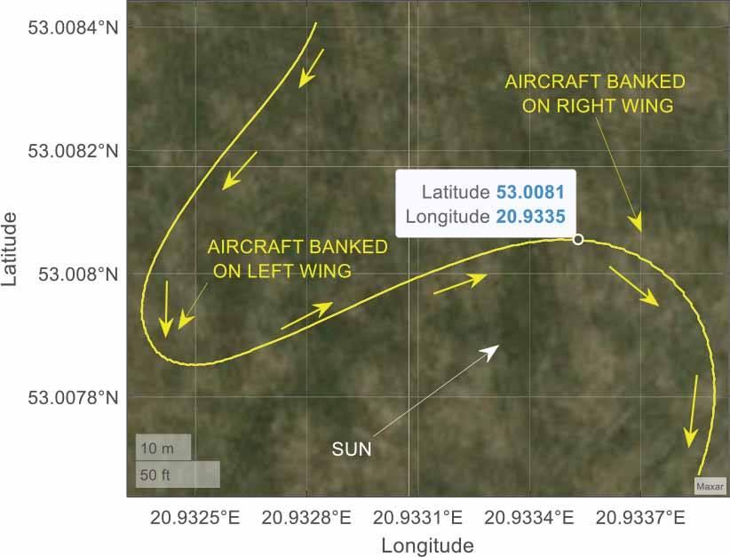
Figure 29.
Approximate aircraft location at energy peak (case 3, enlarged view)