

Figure 1.
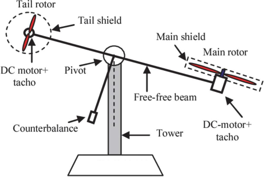
Figure 2.
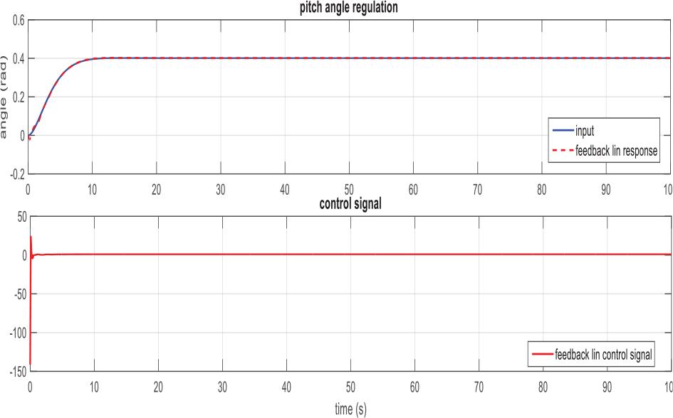
Figure 3.
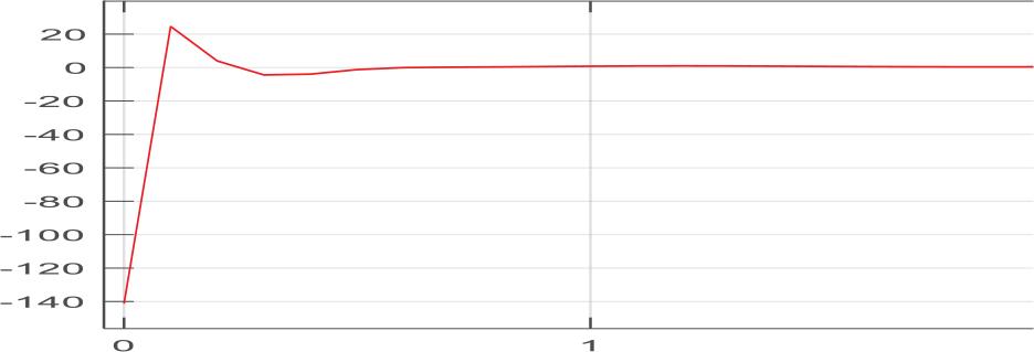
Figure 4.
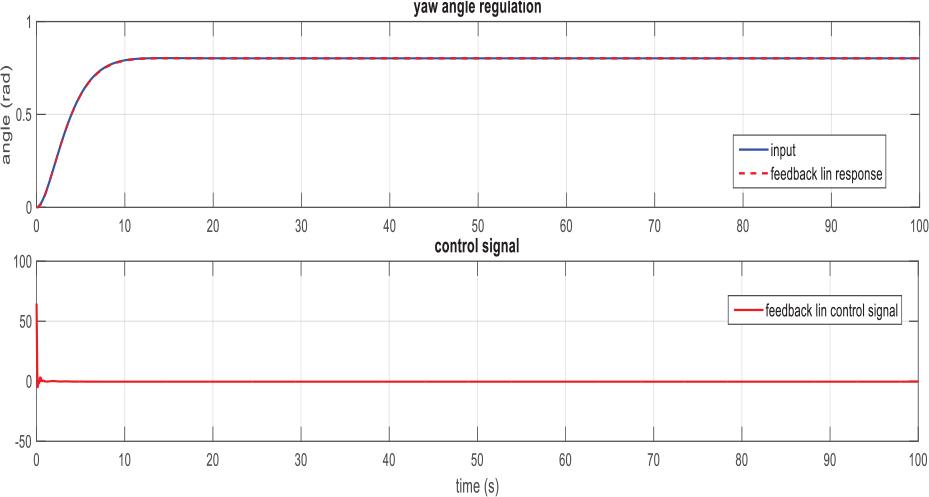
Figure 5.
Figure 6.
Figure 7.
Figure 8.
Figure 9.
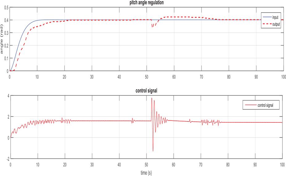
Figure 10.
The TRMS parameters – from the “feedback” manufacturer
| Parameters | Values |
|---|---|
| I1 – main rotor moment of inertia | 6.8.10-2 Kg/m2 |
| I2 – tail rotor moment of inertia | 2.10-2 Kg/m2 |
| a1 – nonlinearity parameters | 0.0135 |
| b1-nonlinearity parameters | 0.0924 |
| a2-nonlinearity parameters | 0.02 |
| b2-nonlinearity parameters | 0.09 |
| Mg-moment of gravity | 0.32 N.m |
| B1ψ – parameter of the friction moment function | 6.10-3 N.m.s/rad |
| B2ψ – parameter of the friction moment function | 1.10-3 N.m.s/rad |
| B1ϕ – parameter of the friction moment function | 1.10-1N.m.s/rad |
| B2ϕ – parameter of the friction moment function | 1.10-2 N.m.s/rad |
| Kgy – gyroscopic moment parameter | 0.5 S/rad |
| K1-gain of motor 1 | 1.1 |
| K2gain of motor 2 | 0.8 |
| T11 – motor 1 denominator parameter | 1.1 |
| T10 – motor 1 denominator parameter | 1 |
| T21 – motor 2 denominator parameter | 1 |
| T20 – motor 2 denominator parameter | 1 |
| Tp – coupling moment parameter | 2 |
| To – coupling moment parameter | 3.5 |
| Kc–-coupling moment gain | -0.2 |
Tracking error values
| Feedback-lin | ||
|---|---|---|
| MA of error | Pitch | MAE = 0.0066 |
| Yaw | MAE = 0.0023 | |
| MS of error | Pitch | MSE = 5.7529−05 |
| Yaw | MSE = 7.0992e−06 | |
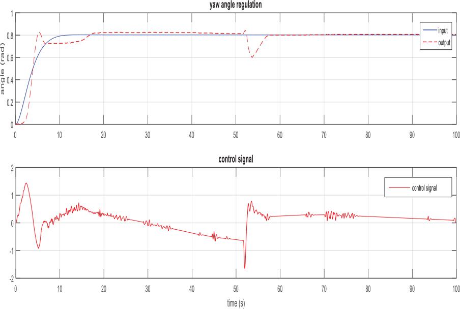
Regulation error values
| Feedback-lin | ||
|---|---|---|
| M-A of error | Pitch | MAE = 0.0100 |
| Yaw | MAE = 0.0060 | |
| M-S of error | Pitch | MSE = 6.6811e−04 |
| Yaw | MSE = 4.4122e−04 | |