
1.0 Introduction
In the medium term, hydrogen and fuel cells will play an important role in the transition towards a sustainable energy economy and the electrification of mobility (Moriarty & Honnery, 2019; Singh et al., 2015). The most important challenges that need to be addressed in order to prepare the market for the relevant technologies are further increasing the service life, improving the performance characteristics and reducing the manufacturing costs of the relevant components and systems, as well as establishing a supply infrastructure consisting of storage and distribution networks for hydrogen produced from renewable sources. The latter in particular is a prerequisite for a broad market launch and for efficient, user-acceptable operation of fuel cell vehicles in everyday life.
Due to its universal production and utilization possibilities, the various energy sectors can be well connected using hydrogen (Mazloomi & Gomes, 2012). As a chemical energy store that can be produced efficiently via electrolysis, hydrogen has great potential to bring renewable energy into the mobility sector and thus achieve national CO2 emission reduction targets in this area too. Hydrogen offers the highest gravimetric energy density, and the fuel cells ensure very high conversion efficiency even in small sizes, which allows electromobility with the usual ranges and refueling times, and with the usual comfort levels.
With this in mind, the Karlsruhe Institute of Technology (KIT) aimed to further develop this technology, and, with the bus shuttle service, a corresponding system solution had to be technically and economically validated and demonstrated. At the same time, the system had to be usable as research, development and training infrastructure for new hydrogen technologies and serve as an additional supply point for the alternative fuel of hydrogen in the North Baden region.
On the initiative of and with financial support from the Ministry of the Environment of the State of Baden-Württemberg, the KIT Executive Board decided in late 2009 to set up a hydrogen refueling station as a key element of a filling station of the future. In an initial meeting with representatives of the ministry, the state expressed its intention to do more for the expansion of hydrogen infrastructure and, if necessary, for corresponding vehicles.
Key aspects of the facility to be built were that it should be open-access and high-utilization. A combination of the KIT refueling station and fuel cell buses, which would replace the conventional diesel buses on the KIT shuttle line, seemed promising. The concept for this project was initially developed with Energie Baden-Württemberg AG (EnBW). The Letter of Intent was signed in November by KIT, the Ministry of the Environment of the State of Baden-Württemberg, the bus manufacturer EvoBus and the local public transport company Verkehrsbetriebe Karlsruhe GmbH (VBK). The funding application was submitted to the Ministry of the Environment of the State of Baden-Württemberg on 17 December 2010 and the funding was approved on 23 December 2010. The two H2 fuel cell buses were delivered to KIT in October 2011, but due to problems with the commissioning of the refueling station, no scheduled operation of the KIT H2 shuttle was possible until June 2013.
2.0 KIT Shuttle Service
2.1 KIT shuttle buses and refueling station
The KIT shuttle bus service is exclusively used to take students and KIT employees on business activities to the various campuses that are spread across the city. Therefore, the service is offered only on working days from 7:30 AM to 7:30 PM. The approximately 30-km-long route starts at Campus South and runs via Campus East to Campus North, from where it takes a direct route back to Campus South. The bus runs every half hour, with one bus running all day and the second only in the morning and evening at peak times. There are three refueling stops a day, with the bus that runs all day being refueled twice a day and the other only once.
The two hydrogen fuel cell hybrid buses used for the shuttle service were manufactured by Evobus (Figure 1). They are of the basic Citaro type, 12-meter-long standard city buses, and have two 60 kW Proton Exchange Membrane (PEM) fuel cell stacks each. Each bus has seven Type III pressure vessels (tanks) with a volume of 205 liters each that can store a total of 35 kg of hydrogen at a pressure of 350 bar. This results in a range of at least 300 km, but the actual ranges achieved are much higher. Type III tanks consist of a thick outer carbon fiber wrapping that bears the entire pressure load and a thin inner metallic liner to ensure the impermeability ot the tank.
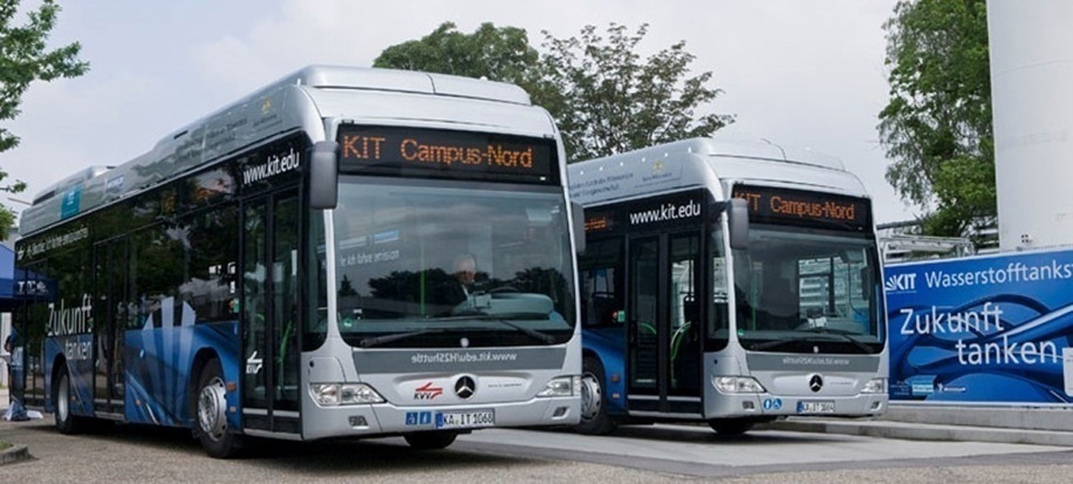
Figure 1
The two H2 fuel cell hybrid buses of the KIT shuttle in front of the H2 refueling station at KIT.
The bus is electrically powered by two wheel-hub motors on the rear axle. The motors are primarily supplied with electrical power from a lithium-ion accumulator (battery). The accumulator is charged by the fuel cells when required. With the battery alone, the bus only has an emergency reserve of approximately 10 kilometers. The buses also have low-floor technology and a conventional seating arrangement, and are fully air-conditioned.
The seven Type III hydrogen tanks of the buses are located below a cover in the front part of the roof of the bus (see Figure 2). The cover over the tank system is sufficiently ventilated and additional openings in the tank cover direct any escaping gas upwards in the event of a malfunction. The tank recess is sealed gas-tight from the passenger compartment and is ventilated via the tank cover. In the event of excessive heat in the hydrogen tank system (e.g., a fire), the hydrogen is vented via fusible plugs as pressure relief devices at a central point on the vehicle roof. The main properties of the Luxfer Dynecell 3W205H350 Type III hydrogen tanks are listed in Table 1.
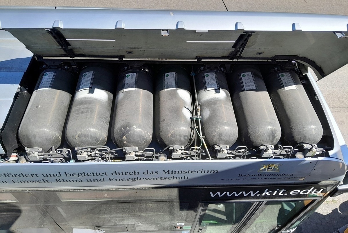
Figure 2
The seven Type III hydrogen storage tanks in the roof of a H2 shuttle bus.
Table 1
Main properties of the shuttle bus hydrogen tanks (Luxfer Cylinders, 2026).
| PARAMETER | SPECIFICATION |
|---|---|
| Manufacturer | Luxfer Dynecell |
| Model/Type | 3W205H350 (Type 3) |
| Technology | Al liner with carbon fiber wrapping |
| Diameter [mm] | 415 |
| Length [mm] | 2110 |
| Weight [kg] | 95 |
| Water Volume [L] | 205 |
| Service Pressure [MPa] | 35 |
| H2 Storage capacity [kg] | 4.9 |
| Certification | EC79/ECE R134 |
A photo and schematic sketch of the KIT H2 refueling station for the KIT shuttle buses are shown in Figure 3. The hydrogen supplied in the refueling station comes from the chlor-alkali electrolysis plant of BASF SE in Ludwigshafen, where it is a by-product. It is purified there to 5.0 quality (99.999% H2) and then compressed to 200 bar for transport to KIT via a H2 trailer. To fill the large storage vessel, the trailer driver connects a hose to the filling panel and allows the hydrogen to flow from the trailer (pTrailer = 200 bar) into the storage vessel until it reaches the maximum pressure of pStorageMax = 42 bar. When full, the large storage vessel contains approximately 250 kg of gaseous hydrogen. From the large storage vessel, the hydrogen is conducted into the compressor container, where it is compressed by a two-stage diaphragm compressor from typically 10–40 bar to 450 bar in the adjacent hydrogen high-pressure steel cylinder bundles (Wystrach 400.180/L450-0204), which have a maximum operating pressure of 500 bar. The high-pressure bundles are divided into three storage banks and can store a further 150 kg of hydrogen, approximately. With this arrangement and the appropriate withdrawal and filling strategies, the longest possible availability of the highest possible pressure is achieved.
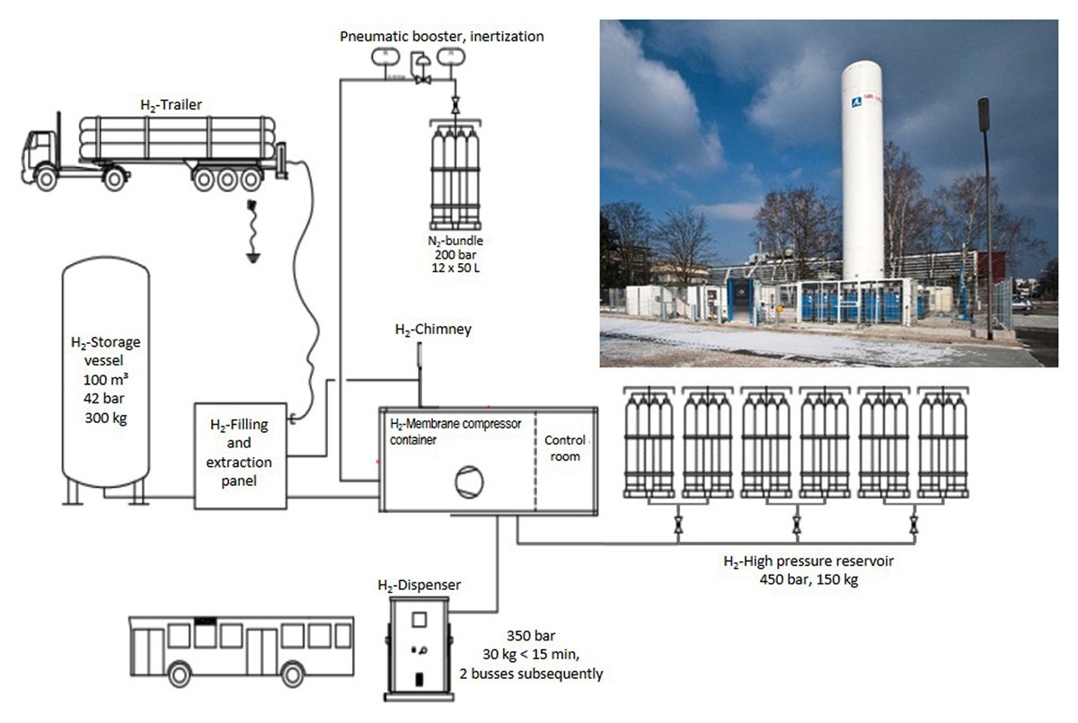
Figure 3
Photo and schematic sketch of the KIT H2 refueling station for the KIT shuttle buses.
Like every refueling station, the KIT H2 refueling station also has an electrically conductive surface. Nevertheless, when a bus arrives, it must be electrically grounded (formally required by the bus manufacturer; cable for this purpose provided at station) before it can be connected to the 350 bar filling point on the dispenser via its connecting position close to the rear passenger door. The driver or the refueling attendant then switches on the system and starts the refueling process from the control panel at the dispenser.
At the beginning of the completely automated refueling procedure, the refueling station gives a short pressure pulse to the dispenser and observes whether a strong pressure decrease indicates a leak inside it, which would immediately stop the filling procedure. When no leak is detected, the filling procedure starts from the storage bank which has the lowest pressure (but which is higher than the bus tank pressure), since the driving force for the filling process is the pressure difference between the storage bank and the bus tanks. To avoid pressure shocks inside the H2 system and the tanks, a pressure regulator is positioned downstream from the connecting point. During the filling procedure, the tank pressure increases, while the storage bank pressure decreases. When the pressure difference is reduced to a value of approximately 50 bar, the filling station automatically switches to the next storage bank, but the storage bank with the highest pressure is always used last in the procedure, to achieve the highest possible filling pressure in the bus tanks. When the bus tanks are pressurized up to 350 bar, the connection to the station is closed and the dispenser is depressurized via the chimney of the filling station. During the completely automated refueling process, the driver merely has to wait until the end of the procedure is signaled on the display at the dispenser. Then, the filling hose and the grounding cable are disconnected before the bus can leave the station. The refueling time for a bus with 30 kg H2 is approximately 10 to 15 minutes.
During operation, the H2 from the bus tanks is consumed by the fuel cell system, which constantly charges a high-voltage battery that provides the required electric power for the two wheel-hub motors on the rear axle. All components of the H2 fuel cell system, as well as the battery, are located in the roof of the bus for safety reasons.
2.2 Status of the buses and derivation of the strategy
At the beginning of the shuttle service, the buses were often unavailable, which was caused by both the power electronics and conventional components (compressor, door opener, etc.). Drivers were afraid to operate the buses due to the cumbersome starting and switching-off procedures of the buses, which can lead to faults in the technology. The initially poor availability led to mixed initial feedback from users. In operation, the buses have proven to be very energy-efficient and, with appropriate production of the hydrogen used, appear to be an interesting, albeit currently still expensive, option for reducing CO2 emissions in transport. The technology also reduces noise, particulate matter and nitrogen oxide (NOx) pollution in the environment.
By the end of 2013, the main problems in the hydrogen bus service had been overcome by better replacement parts and more extensive driver training. However, it took two further years (to the end of 2015) before the system (buses and refueling station) showed high availability and thus earned high acceptance among the customers of the KIT shuttle. Also, many interested people took the opportunity to view the buses on one of the many occasions when they were presented to the public (Hannover Fair, open-house days at KIT, company excursions, etc.). The main positive feedback emphasized the very quiet and smooth driving performance.
In the years leading up to 2021, the buses worked quite reliably, which led to high availability rates and large passenger numbers. Therefore, in 2020, with the expiration of the lifetime of the buses’ hydrogen tank system in sight, the first considerations and preparations were made to extend the bus service, using the existing buses, for a further five years. An important factor in these considerations was the comparatively low kilometer performance of the buses, which were operated only on working days for a maximum of 12 hours.
Hydrogen fuel cell buses are subject to an annual general inspection, which is carried out by the Technical Inspection Association TÜV SÜD for the KIT shuttle busses. In this general inspection, the buses are inspected for road safety and the gas system is checked for leaks. In addition, a safety inspection is carried out three times a year, during which the buses are checked for road safety and leaks in the same way as during the main inspection. Smaller inspections are also carried out every six months.
Despite these regular inspections, the operating license for the high-pressure H2 part is defined by the tank/vehicle manufacturer. The pressure system is certified in accordance with European Pressure Equipment Directive (Directive 97/23/EC. 1997), which was valid at the time the tanks and buses were built. The system is designed for 10,000 operating cycles and 5,000 refueling cycles of the pressure vessels. The service life of the system is specified as 10 years (expiring on 20 June 2021), amd that of the pressure vessels is 20 years, lasting until May 2031. Therefore, in spring 2021, the following four points were identified as crucial for an extension of the operating license:
The service life for the present generation of tanks has been estimated by the manufacturer to be 20 years. At the time of the analysis (2021), the tanks therefore had a remaining service life time of approximately 10 years (until 2031). This date could also be found on the tank cylinders (‘Do not use after 2031/05’).
According to the certification, the system is designed for a maximum number of operating and refueling cycles, which are as follows:
• 10,000 operating cycles for the system, and
• 5,000 refueling cycles for the pressure vessels.
The problem with these values is that the numbers of operating and refueling cycles cannot be read from the operating system of the buses. To extend the operating license, these numbers must be determined, documented and proven to be below the maximum.
In Germany, the Ordinance on Industrial Safety and Health requires an inspection of all safety pressure valves after 10 years according to Technical Regulation – Worksheet DVGW G 469 (A) (DVGW, 2019), issued by the German Association of the Gas and Water Industry (DVGW). However, the tank system of the buses does not contain any classic safety valves. Protection against overloading is ensured by appropriate safety devices at the refueling station. The tank valve system includes a device with overtemperature protection for each tank, which opens at temperatures > 100°C and drains the tank. However, a safety pressure valve is located downstream of the pressure regulator and upstream of the fuel cells. This valve must be tested or exchanged in order to extend the operating license.
To extend the operating license, a pressure test of the pressure vessels must be carried out every 10 years, in which the pressure resistance is tested at 1.5 times the nominal pressure. According to EvoBus, the tests must not be carried out with water as the pressure medium, because a test with water in combination with additional air contact with the inner wall of the tank, which consists of pure non-passivated aluminum, could lead to corrosive damage to the aluminum layer during the test and render the containers unusable.
3.0 Extending the Operating License
On the basis of the four key points described above, the following actions were performed to achieve an extension of the operating license for the KIT shuttle buses. To distinguish between the two buses, the numbers on the license plates were used, so one bus was named ‘1064’, and the other ‘1068’.
3.1 Service life of the tank system
The service life for this generation of tanks has been estimated by the manufacturer to be 20 years. Therefore, no further actions were required, as the tank system still had a remaining service lifetime of 10 years in 2021.
3.2 Maximum number of refueling and operating cycles for the tanks and valves
The number of refueling and operating cycles cannot be read from the operating system of the buses, so another possibility for tracking down these numbers had to be found. Fortunately, the buses had spent almost their entire service life in operation as shuttle buses in only one city and thus were almost exclusively driven by drivers from the local public transport company and, with very few exceptions, exclusively refueled at the KIT H2 refueling station.
Usually, the KIT H2 shuttle starts in the morning at the beginning of the service and is turned off at the end of service. In between, the buses are not turned off, except for refueling, where the vehicle has to be turned off for safety reasons. One shuttle line drives from the morning to the evening with two refueling stops in between, while the other line only operates in the rush hours of morning and afternoon, with one refueling stop during the afternoon service. Table 2 summarizes the refueling and operating cycles accumulated by both lines during their daily service.
Table 2
Number of refueling and operating cycles for the tanks and valves of both KIT H2 shuttle buses during their daily service.
| SERVICE | REFUELING CYCLE | OPERATING CYCLE | SERVICE | REFUELING CYCLE | OPERATING CYCLE |
|---|---|---|---|---|---|
| Full day | Rush hour | ||||
| Service start | 1 | Start service 1 | 1 | ||
| Refueling stop 1 | 1 | End service 1 | |||
| Refueling stop 2 | 2 | 2 | Start service 2 | ||
| Refueling stop | 1 | 2 | |||
| Service end | 3 | End service 2 | 3 | ||
As Table 2 shows, in the full-day service, a total of 2 refueling cycles and 3 operating cycles are accumulated, while in the rush-hour service only 1 refueling cycle is performed, while 3 operating cycles are completed. Both lines were served alternately by both buses, and thus, on average, 1.5 refueling cycles and 3 operating cycles (ratio 1:2) were generated per bus, per day.
The service days of the buses were also recorded in their logbooks at the local public transport company over their entire service life. This allowed estimation of the number of refueling and operating cycles for the tanks and valves of both shuttle buses. The values were then checked on the basis of the data recorded at the KIT H2 refueling station, where the bus driver has to identify themselves and the respective bus at the dispenser control panel to prove their refueling authorization prior to the refueling procedure. This data was available for the complete service life of both H2 shuttle buses and it was therefore possible to compile a detailed reconstruction of the number of refueling and operating cycles for both buses. The values determined in this way are summarized in Table 3.
Table 3
Total number of refueling and operating cycles for the tanks and valves determined for both KIT H2 shuttle buses.
| OPERATION | BUS 1064 | BUS 1068 | ALLOWED: TANK | ALLOWED: SYSTEM |
|---|---|---|---|---|
| Refueling cycles | 1,289 | 1,354 | 5,000 | |
| Operating cycles | 2,289 | 2,268 | 10,000 |
As Table 3 shows, the numbers determined are significantly lower than the values specified for the tanks and valves in the certification of the shuttle buses. Even for the refueling cycles, with only 5,000 cycles allowed, only roughly a third of the allowed value was used. Therefore, both tanks and valves could continue to be used and no exchange was necessary. The values shown in Table 3 are also in good agreement with the daily ratio of refueling and operating cycles (1:2) determined using Table 2. The slightly higher number of refueling cycles is due to many test procedures during the commissioning of the refueling station, in which the buses were connected to the station, but not refueled.
3.3 Safety pressure valve test
In industry, safety pressure valve tests are standard procedure. Nevertheless, it was decided to replace the safety valves in the buses with new ones, since two safety pressure valves of the required type were available in stock at the assigned workshop.
3.4 Pressure vessel test
Type III hydrogen storage tanks mainly consist of a thin metal inner liner (in the KIT buses, this was aluminum), fully wrapped with a high-strength carbon fiber composite overwrap. The metal liner handles gas impermeability while the outer composite layer bears the heavy pressure load, allowing safe storage of compressed hydrogen gas up to 350–700 bar. In the past, composite degradation and metal liner fatigue have been identified as primary failure modes, so, in the pressure vessel tests, these topics had to be addressed. In the pressure retention tests at elevated pressure, impermeability can be proven with pressure measurements, while the high pressure level (1.5 times the maximum working pressure) proves the stability of the carbon fiber composite overwrap.
Since no pressure vessel tests with water were allowed, it was decided that Pro-Science GmbH should perform the tests with nitrogen (N2) in a safety vessel at KIT. For the tests, the tanks had to be removed from the buses by the assigned workshop, but, prior to removal and transport, the tanks had to be depressurized and purged with nitrogen for safety reasons. To avoid having unpressurized N2-filled tanks in the buses after the tests, in the first batch only three of the seven tanks from one bus were removed from the vehicle, while the remaining four H2-filled tanks remained in the bus for the moment. In the vehicle, every tank can be opened, purged and closed independently, so the first three tanks were depressurized and purged several times with nitrogen through pressure change flushing before they were removed from the bus and transported to KIT. When the three tanks from the first batch were reinstalled into the vehicle after the tests, the H2 in the tanks from the second batch was used to purge the tanks from the first batch with hydrogen. After purging, they were then pressurized as much as possible with the hydrogen from the second batch. Then, the second batch was purged with nitrogen, removed, tested and reinstalled, before being purged with the hydrogen now stored in the tanks from the first batch. In this way, unpressurized N2-filled hydrogen tanks could be avoided, which is a very crucial point, since no dedicated H2 refueling equipment was available in the workshop. Purging and filling the tanks with pressurized H2 from cylinders after the tests would therefore have been a very time- and hydrogen-consuming procedure. The tank filling level after the testing of both batches was not sufficient to drive the buses to KIT, but using one 300-bar H2 bundle was sufficient to bring the buses back to the H2 refueling station at KIT after the end of the test campaign.
For the pressure vessel tests, one tank was mounted on a rack inside the safety vessel in the hydrogen test center at KIT. From inside the vessel, the tank was connected with a pipe to the rest of the facility outside the safety vessel (see Figure 4). This safety vessel has a volume of 8.8 m3 and is designed for a static pressure of 120 bar, which allows the vessels to be tested with gaseous media. Even in the case of a tank rupture at the highest pressure (approximately 550 bar) during a test, a pressure increase of only 12.6 bar would result inside the safety vessel, and any debris or missiles would also remain captured inside.
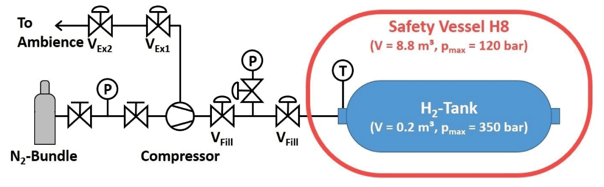
Figure 4
Sketch of the pressure vessel test facility at KIT.
The filling branch of the test facility mainly consisted of a 300-bar N2 bundle with 12 gas cylinders and a powerful compressor. The compressor was needed to reach the required test pressure ptest, which must be at least 1.5 times the maximum working pressure pmax of the tank, which amounts to:
At the beginning of the test, the bypass function of the compressor is used, which allows the tank to be filled slowly up to the bundle pressure without using the compressor. After having reached the bundle pressure, the tank is further pressurized using the compressor. During the filling procedure, which takes several hours, the temperature of the gas is closely monitored to ensure it remains far below a value of Tmax = 85°C, above which damage to the liner of the tank’s inner surface might occur. If necessary, the process is paused to compensate for the temperature increases in the tank due to the nitrogen compression. When a pressure of approximately 550 bar is reached, the compressor is turned off and the tank is sealed.
Since no regulations for testing of high-pressure tanks with gaseous media were available, a procedure similar to the German DVGW Regulation G 469 (A) (DVGW, 2019) procedure was chosen and agreed with the regulatory body (TÜV SÜD). In the simplified ‘Pressure Measurement Procedure with Air B3’ of this regulation, the vessel is pressurized up to a maximum pressure value of 5 bar, before the pressure drop is determined. According to the procedure, the pressure drop is not determined immediately after the end of the pressurization, but after a settling time that can be calculated using Equation 2:
with tset being the settling time in hours and ptest the test pressure in bar. The reason for this settling time is the temperature and pressure increases in the tank due to the isochoric compression during the refueling procedure. After refueling, temperature and pressure decreases occur even in perfectly tight tanks due to thermal losses after the pressurization. Therefore, the settling time is used to minimize the influence of these thermal losses on the evaluation of tank impermeability.
Another method for determination of the settling time is to take the time after the gas content has reached a quasi-steady state, in which the pressure no longer changes significantly and all transient processes have been completed. Since the calculated settling time of 525 h (approximately 20 days) was not practicable, a settling time of approximately 30 min was chosen on the basis of the recorded pressure and temperature curves.
After the end of the settling time, the pressure drop is determined for a test duration that is defined by the formula given in Equation 3:
with the test duration ttest in minutes and the volume of the geometry Vgeo in m3. For the current test set-up, the test duration amounts to 0.1025 h, which corresponds to 6.15 minutes.
According to DVGW (2019), for a maximum test pressure of 5 bar, a permissible pressure drop Δpperm of 50 mbar might occur in the test volume in order to remain within the tolerance limit for a ‘pressure drop within the permissible tolerance’. This pressure difference corresponds to a pressure drop of 1% of the initial test pressure, so the permissible pressure drop for the current set-up was calculated using Equation 4:
with Δpperm and ptest being the permissible pressure drop and the test pressure in bar, respectively.
Therefore, if the pressure drop Δptest measured in a test follows Equation 5, the test is passed successfully.
with Δptest and Δpperm being the measured pressure drop and the permissible pressure drop in bar, respectively.
In the left graph of Figure 5, the complete procedure of a pressure vessel test can be followed via pressure and temperature curves. At t ≈ 1.2 h, the pressure equilibrium between gas bundle and tank was reached and the compressor was turned on to achieve higher pressure levels inside the tank. This faster pressurization led to a fast temperature increase inside the tank and so, approximately 10 min later, the compressor was turned off after the inner tank temperature approached a value of T ≈ 50°C, to remain far below a maximum temperature level of Tmax = 85°C, above which the liner inside the tank might have been damaged. The tank was then left to settle for 10 minutes, which caused a temperature and thus pressure decrease due to heat transfer to the environment. During the following 1.5 h, the compressor was turned on and off again three times, which resulted in three further temperature peaks and pressure steps. The tank was then left to settle for a longer period of approximately 1 hour, before, at t ≈ 3.7 h, the compressor was turned on again to approach the desired test pressure region of more than 500 bar.
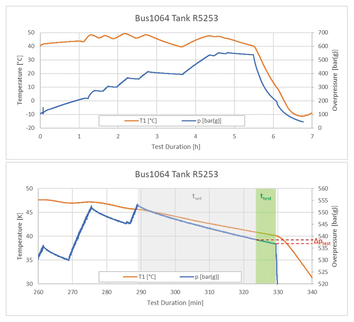
Figure 5
Example of pressure and temperature readings of a test (top) and detail of measurements (bottom) with illustration of the test evaluation.
The right graph in Figure 5 shows the details of the main part of the test, where, in two further pressurization steps, the tank pressure was stabilized at a value of approximately 550 bar, before, at t ≈ 290 min, the settling time of approximately 30 min (grey-shaded region in graph) began. Approximately 40 min later, the test was stopped and the depressurization of the tank was initiated. For the test duration ttest, which is the time interval of 6.15 minutes prior to the depressurization (green region in graph), the pressure drop Δptest inside the tank was determined (highlighted red in graph).
With the method described above, all tanks from both shuttle buses were tested at KIT. Table 4 summarizes the test results and shows that all tanks passed the pressure vessel tests successfully.
Table 4
Summary of pressure vessel test results for both KIT H2 shuttle buses.
| BUS 1064 | BUS 1068 | ||||||
|---|---|---|---|---|---|---|---|
| TANK # | SERIAL # | Δpperm | Δptest | TANK # | SERIAL # | Δpperm | Δptest |
| 1 | R7241 | 5.25 | 1.303 | 1 | R7429 | 5.25 | 2.518 |
| 2 | R9492 | 5.25 | 2.373 | 2 | R7436 | 5.25 | 3.016 |
| 3 | R9507 | 5.25 | 2.156 | 3 | R9500 | 5.25 | 2.719 |
| 4 | R5253 | 5.25 | 1.696 | 4 | R9504 | 5.25 | 1.814 |
| 5 | R7431 | 5.25 | 2.134 | 5 | R7397 | 5.25 | 2.350 |
| 6 | R7395 | 5.25 | 2.638 | 6 | R7409 | 5.25 | 1.360 |
| 7 | R7398 | 5.25 | 2.399 | 7 | R7393 | 5.25 | 2.310 |
After the end of the pressure drop measurement, the depressurization procedure of the tank was started at a pressure close to 525 bar. Due to this very high pressure level, it was important not to discharge the tanks too fast. Therefore, to protect the tank and the facility, a special procedure was carried out in which the pipe volume in between the valves VEx1 and VEx2 was pressurized by opening VEx1 (compare Figure 4). Then, after VEx1 had been closed, valve VEx2 was opened for a short time to release the overpressure to the environment. Using this procedure, the tank was usually emptied within 1½–2 hours without overly strong temperature decreases below the minimum operation temperature of the tanks of Tmin = –40°C.
Using the procedure described above, all 14 tanks from the two buses successfully passed the strength tests at KIT. After reassembly and a thorough optical inspection of the tank system, a final leak test of the complete pressure systems of both buses was carried out at the assigned workshop.
Together with the reconstructed numbers for the refueling and operating cycles of the tanks and valves of the system, which were far below the maximum values allowed, both H2 shuttle buses received an operating license extension of five years in August 2021. With this extension, the H2 shuttle service could be operated for more than three further years with the existing buses, before they finally had to be decommissioned in 2025 due to a spare parts shortage.
4.0 Conclusions
In June 2021, the operating license for the tank system of the two KIT H2 shuttle buses was about to expire after 10 years of service, as defined by the tank manufacturer Dynatec and the bus manufacturer EvoBus. Obtaining an extension of the operating license seemed feasible, since the buses were operated rather restrictively compared to regular bus services in public transportation. In their service life as shuttles, the buses were only operated on working days for a maximum of 12 hours and had therefore only accumulated a comparatively low mileage up to this point, which had also resulted in a relatively low number of refueling operations. According to the certification, the tank system was designed for 10,000 operation cycles and 5,000 tank refueling cycles, whereas the service life of the system was specified as 10 years and that of the tanks as 20 years.
In spring 2021, the first plans for the procedure for gaining a license extension were made. The main problem was determining the number of operation and refueling cycles that the buses had experienced during their first 10 years of service life. Unfortunately, the number of cycles is not documented or counted by the bus, which is a significant drawback when aiming to assess the status of the certification’s expiry. Fortunately, both shuttle buses had been operated for almost their entire service lives as shuttle buses in only one city and thus they had almost exclusively been driven by drivers from the local public transport company and, with very few exceptions, exclusively refueled at the KIT H2 refueling station. Therefore, by analyzing the logbooks of the operating company and cross-checking with the data recorded by the KIT H2 refueling station, the number of operating and refueling cycles for both buses could be reconstructed. A comparison with the certified cycle numbers revealed that the limits were not yet close to being reached.
Before the tanks could be granted a lifetime extension, strength tests of all 14 of the buses’ tank cylinders had to be performed with gaseous N2, since the tanks could not be filled with water as pressurizing medium, as stated by the bus manufacturer. For safety reasons, all tests were performed in a dedicated tank testing facility that was installed in a safety vessel of the hydrogen test center HYKA at KIT. For the tests, the tanks had to be removed from the buses by the assigned workshop, but, prior to removal and transport, the tanks had to be depressurized and purged with nitrogen for safety reasons. To avoid having unpressurized N2-filled tanks in the buses after the tests, the seven tanks of one bus were removed in two batches of three and four. While the tanks of one batch were tested at KIT, the other batch remained in the bus to hold as much H2 as possible for the subsequent purging procedure of the tested tanks. In this way, it was possible to test and recondition all seven tanks of a bus with one H2 bus tank refill. The H2 filling level after the testing of both batches was not sufficient to return the buses to KIT, but using one 300-bar H2 bundle was sufficient to bring the buses back to the H2 refueling station at KIT after the end of the test campaign.
Since no regulations for testing high-pressure tanks with gaseous media were available, a procedure similar to the German DVGW Regelwerk G 469 (A) (DVGW, 2019) procedure was developed and agreed with the regulatory body. In the modified Pressure Measurement Procedure with N2, the vessels were pressurized up to 1.5 times the maximum working pressure (525 bar), before the pressure drop was determined after a settling time of approximately 30 minutes. In keeping with the DVGW regulation, a pressure drop of less than 1% (5.25 bar) during the subsequent test duration (6.15 min) was permissible for a successful test. In this way, all 14 tanks of the KIT shuttle buses were tested successfully and gained a license extension.
After the replacement of the safety valves in the buses, a thorough optical inspection and a final impermeability check of the reassembled tank systems, the buses gained an operating license extension for another five years. This meant that the H2 shuttle service could be operated for more than three years with the existing buses, before they had to be decommissioned in 2025 due to a spare parts shortage. To the knowledge of the authors, a procedure like this had never been carried out before in Europe.
The main lesson learned from the procedure to extend the operating license of the tank system of a hydrogen-powered bus is that the bus owner has to provide numbers for the operation and refueling cycles for the complete service life of the bus. Unfortunately, automatic recording of these figures was not initially accounted for, and thus a cumbersome reconstruction had to be performed. Automatic recording of the operations by the bus could be a very useful feature for future H2 buses.