
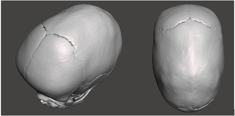
Figure 1
Head CT of a 4-month-old child with congenital craniosynostosis.
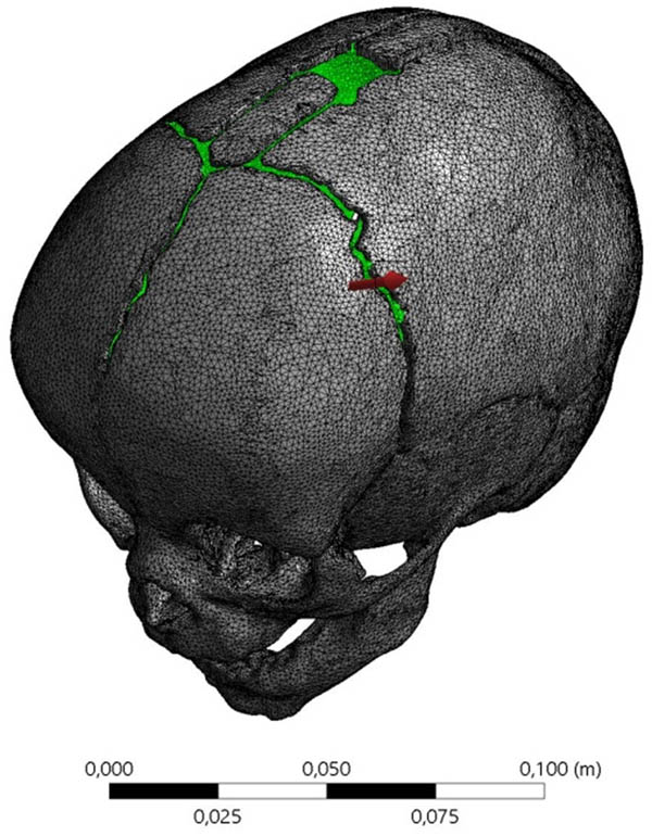
Figure 2
Geometric model of the child’s skull along with the applied mesh.
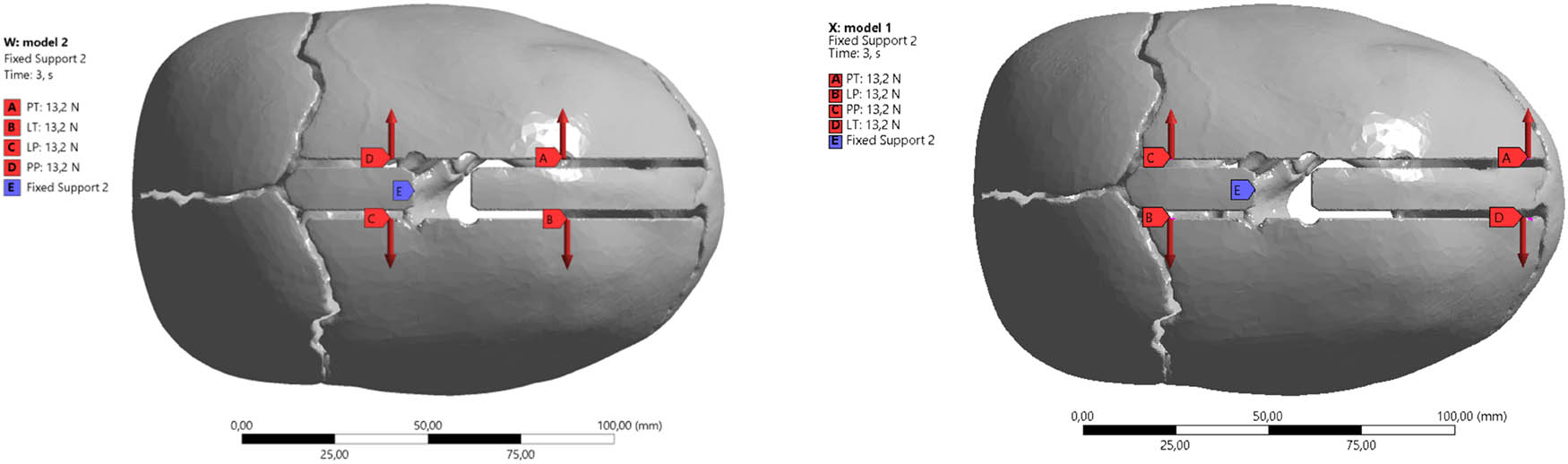
Figure 3
Diagram of the placement of distraction springs: (a) according to the manufacturer’s guidelines (KLS) and (b) proprietary method developed by the authors (AUT).
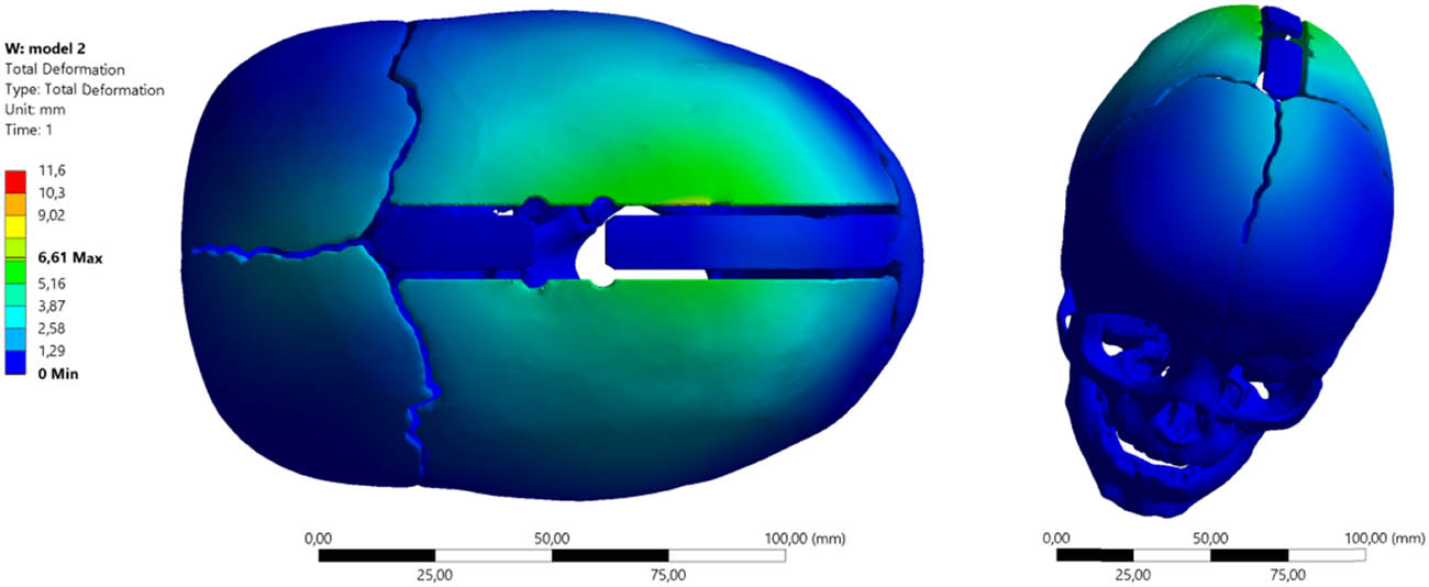
Figure 4
Total deformation of the skull with spring allocation according to the guidelines (KLS1) and the application of spring (S1) with force F1 = 4.8 N.
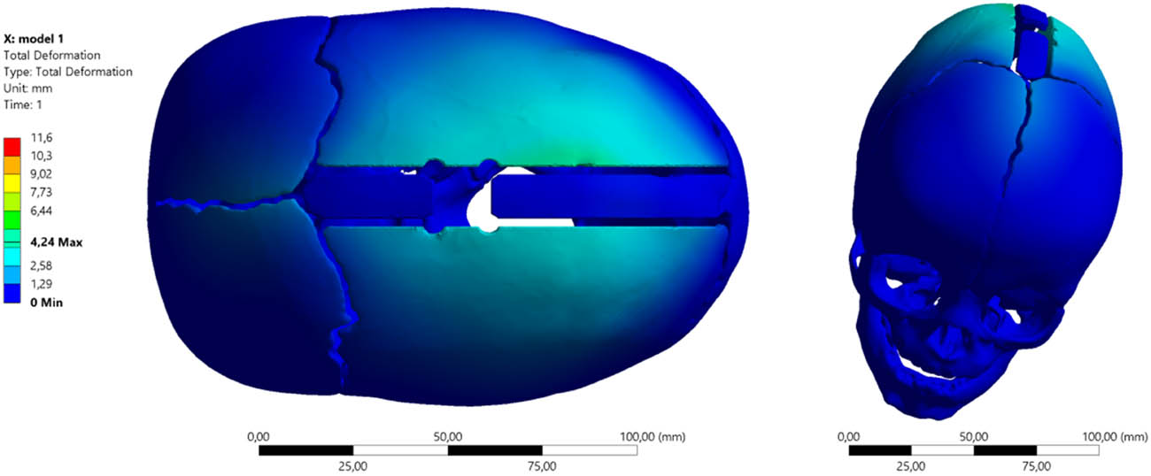
Figure 5
Total deformation of the skull with spring allocation according to the guidelines (AUT1) and the application of spring (S1) with force F1 = 4.8 N.
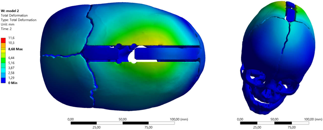
Figure 6
Total deformation of the skull with spring allocation according to the guidelines (KLS2) and the application of spring (S2) with force F2 = 8 N.
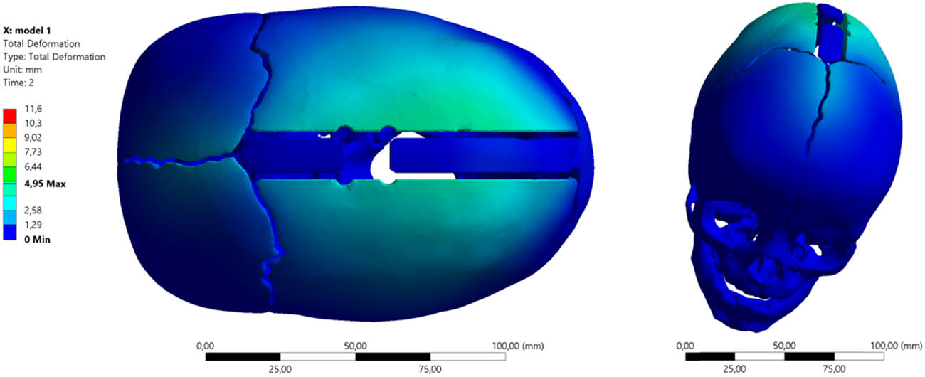
Figure 7
Total deformation of the skull with spring allocation according to the guidelines (AUT2) and the application of spring (S2) with force F2 = 8 N.
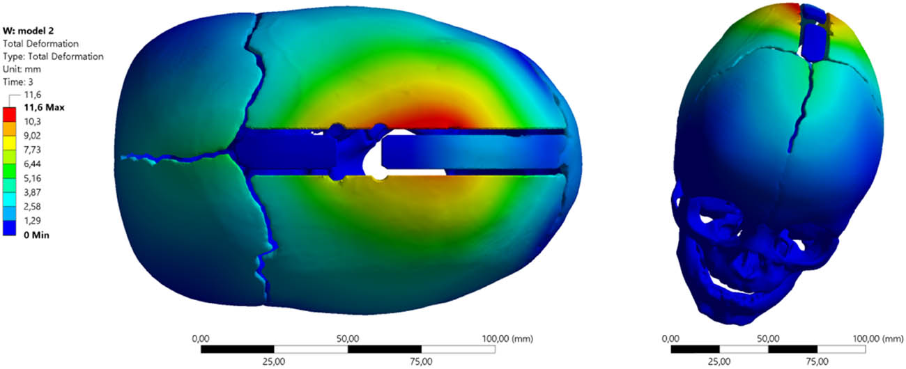
Figure 8
Total deformation of the skull with spring allocation according to the guidelines (KLS3) and the application of spring (S3) with force F3 = 13.2 N.
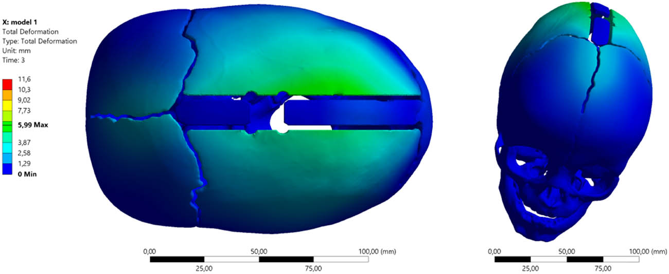
Figure 9
Total deformation of the skull with spring allocation according to the guidelines (AUT3) and the application of spring (S3) with force F3 = 13.2 N.
Table 1
Total deformation of the skull using various springs and two analyzed allocations
| Minimum (mm) | Maximum (mm) | Average (mm) | |
|---|---|---|---|
| KLS Martin spring placement scheme | |||
| (S1) 4.8 [N] | 0 | 6.6125 | 0.43141 |
| (S2) 8 [N] | 0 | 8.6769 | 0.58173 |
| (S3) 13.2 [N] | 0 | 11.587 | 0.80421 |
| Authors’ spring placement scheme | |||
| (S1) 4.8 [N] | 0 | 4.242 | 0.28828 |
| (S2) 8 [N] | 0 | 4.947 | 0.35126 |
| (S3) 13.2 [N] | 0 | 5.994 | 0.44944 |
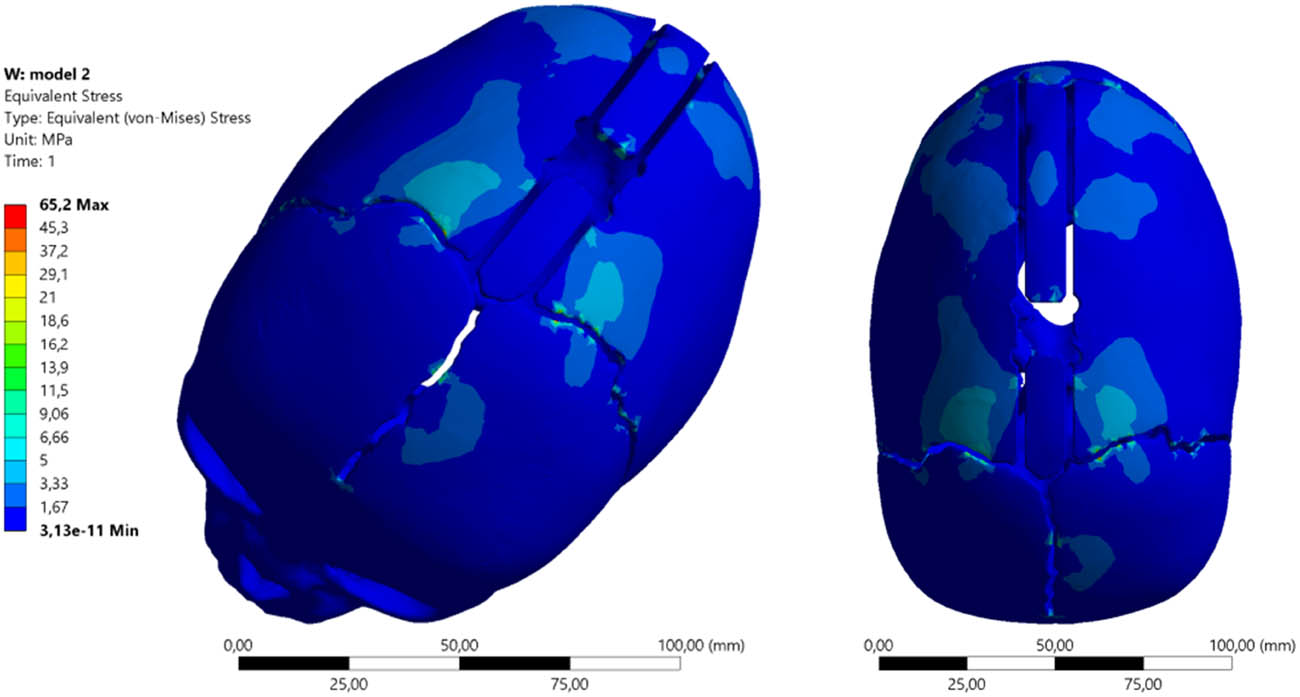
Figure 10
Equivalent von Mises stress maps distractor σzrKLS1 using springs (S1) and spring allocation (KLS1).
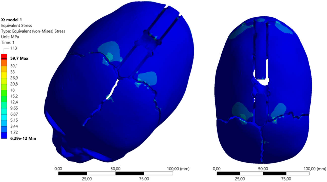
Figure 11
Equivalent von Mises stress maps distractor σzrAUT1 using springs (S1) and spring allocation (AUT1).
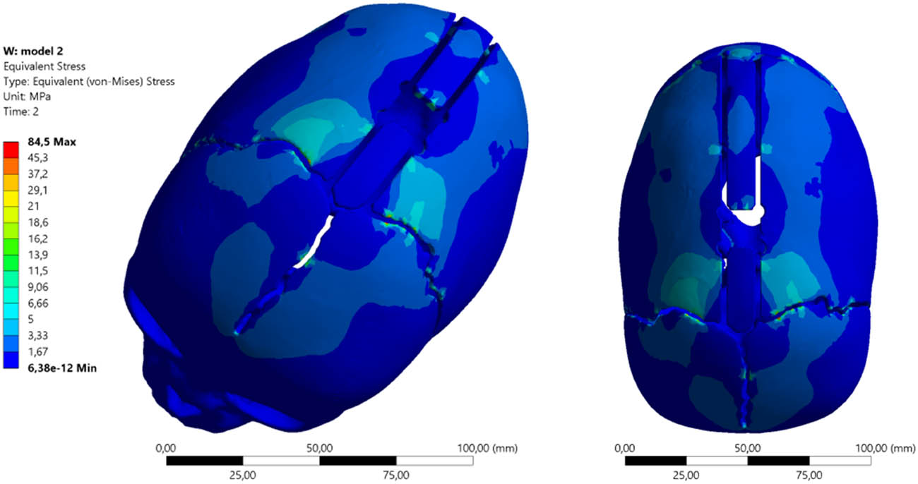
Figure 12
Equivalent von Mises stress maps distractor σzrKLS2 using springs (S2) and spring allocation (KLS2).
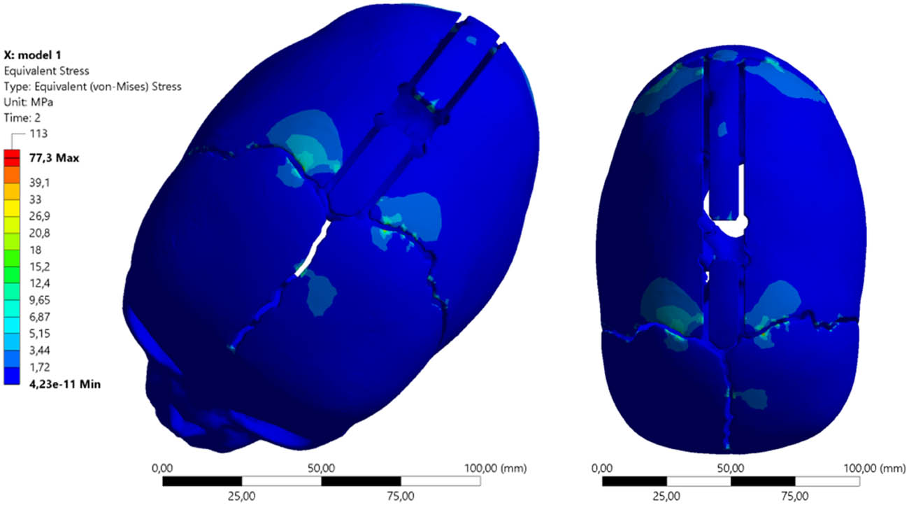
Figure 13
Equivalent von Mises stress maps distractor σzrAUT2 using springs (S2) and spring allocation (AUT2).
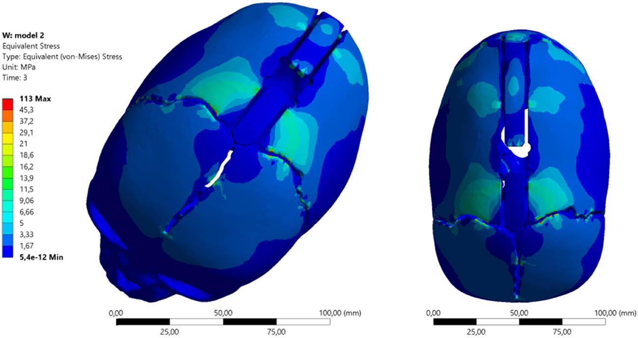
Figure 14
Equivalent von Mises stress maps distractor σzrKLS3 using springs (S3) and spring allocation (KLS3).
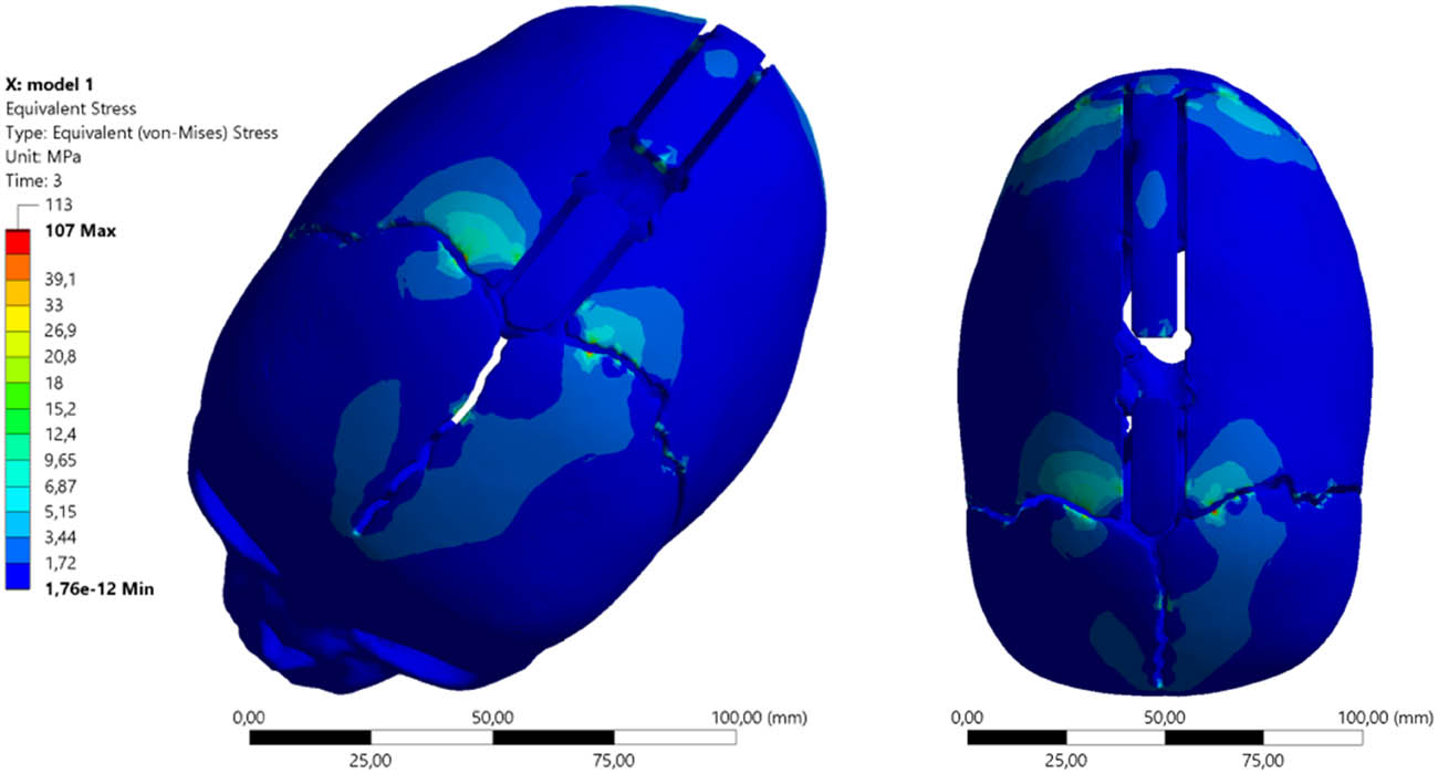
Figure 15
Equivalent von Mises stress maps distractor σzrAUT3 using springs (S3) and spring allocation (AUT3).
Table 2
Summary of numerical test results obtained for the analyzed model
| Minimum (MPa) | Maximum (MPa) | Average (MPa) | |
|---|---|---|---|
| KLS Martin spring placement scheme | |||
| (S1) 4.8 [N] | 3.1343 × 10⁻¹¹ | 65.152 | 0.37997 |
| (S2) 8 [N] | 6.3834 × 10⁻¹² | 84.487 | 0.50891 |
| (S3) 13.2 [N] | 5.4038 × 10⁻¹² | 113.33 | 0.70371 |
| Authors’ spring placement scheme | |||
| (S1) 4.8 [N] | 6.2886 × 10⁻¹² | 59.707 | 0.2639 |
| (S2) 8 [N] | 4.2252 × 10⁻¹¹ | 77.283 | 0.32232 |
| (S3) 13.2 [N] | 1.76e × 10–12 | 106.53 | 0.41685 |
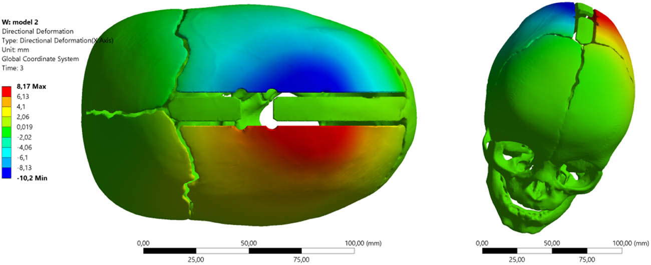
Figure 16
Cranial distraction using springs (S3) and allocation (KLS3).
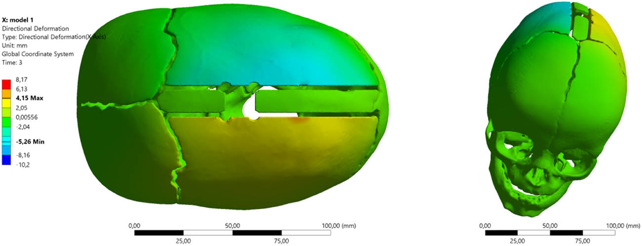
Figure 17
Cranial distraction using springs (S3) and allocation (AUT3).
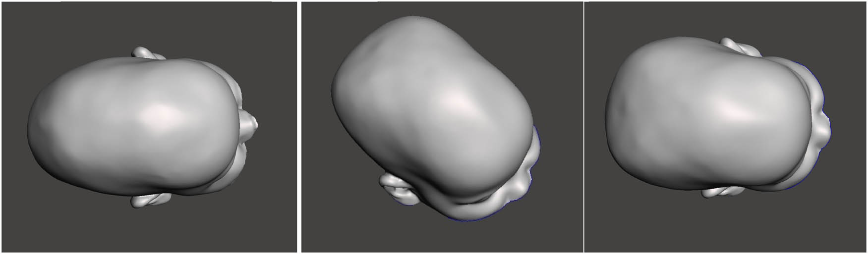
Figure 18
Simulated skull shape after the distraction process and spring allocation (AUT3): (a) skull before surgery, (b) application of distractor (S2), and (c) application of distractor (S3).
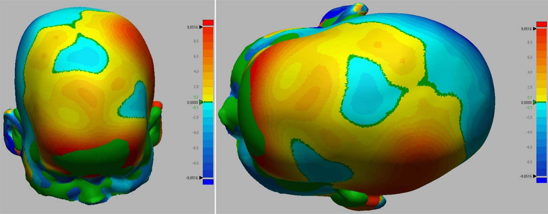
Figure 19
Skull shape deviation maps: (a) before surgery, and (b) after the treatment process.
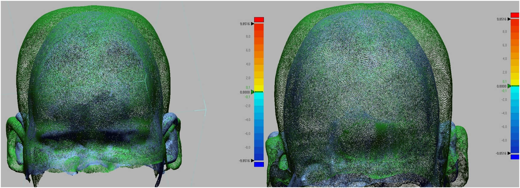
Figure 20
Change in skull shape as a result of the treatment process.