
1. Introduction
Contemporary pediatric craniofacial surgery is at a turning point, where traditional surgical techniques are being redefined through the integration of advanced computational systems, modern biomaterials, and an evolution in the understanding of the molecular biology of developmental defects [1–3].
The infant cranial vault consists of flat bones joined by cranial sutures [4], and membranous soft tissue that is important both at birth and for brain growth. Sutures close naturally over time; however, premature suture closure – called craniosynostosis – is a pathology with a prevalence of 1 in 1,700 live births [5]. Newborns affected by premature closure of the sagittal suture (sagittal craniosynostosis, SC) develop an elongated and narrow head because of compensatory growth of the skull in the direction parallel to the affected suture [6]. Pathology causes that up to 24% of patients affected by non-syndromic craniosynostosis also develop intracranial hypertension with cognitive, speech, and behavioral sequelae [7,8].
Previous studies have aimed to create population-based 3D head shape models for 0–2-year-old subjects to describe head shape variability within a normal population. Such approaches test combined normal and sagittal craniosynostosis (SAG) population models to provide reliable surgical outcome assessments [9]. 3D head shapes of patients with non-cranial pathologies and of SAG patients (pre- and post-op) were extracted from head Computed tomography (CT) or 3D stereophotography scans and processed.
In 2008, stainless steel spring-like distractors were introduced at Great Ormond Street Hospital for Children (London, UK) to support posterior vault expansion – spring-assisted posterior vault expansion – in patients with SC [10,11].
3D reconstructions of each patient’s skull anatomy, before and after surgery, were generated by processing CT images in Simpleware ScanIP. A fixed Hounsfield Unit range (pre-defined in Scan IP for bone segmentation) was used for all patients; artifacts were manually removed. For each patient, the pre- and post-operative intracranial volume (ICV) was measured using either an automatic or a semi-automatic approach [12], after extracting the skull shape as an STL file and post-processing it in MeshMixer (Autodesk Inc.) [13].
In addition, Borghi et al. [3] presented a SAC case study using patient-specific finite element (FE) modeling, which proved that the overall head shape change can be realistically modeled, provided the correct location of springs, as well as spring models, is recorded during surgery: the material properties needed patient-specific tuning to accurately capture spring/skull behavior over time [14]. The literature shows that numerical modeling of craniosynostosis repair can support surgical osteotomy planning and guide the selection of distraction devices [15].
Our fundamental understanding of the physico-mechanical forces that drive the size and shape changes of the cranium during ontogeny is limited. Biomechanical models based on the finite element method (FEM) present a significant opportunity to address this critical gap in our knowledge [16].
The analysis aims to develop a numerical model of a child’s skull that accounts for the location and characteristics of fused sutures and to investigate the effects of spring-assisted cranioplasty using the FEM in ANSYS, predicting biomechanical discrepancies across spring placement methods differing in force and cranial allocation.
2. Materials and methods
A head CT of a 4-month-old child with congenital craniosynostosis was used for the numerical studies. Additionally, to limit the radiation dose, an evaluation of the child’s head shape before and after the surgery was performed using a 3D scanner. The basis for developing the numerical model was a CT scan, which enabled the creation of a model including all the patient’s skull’s anthropometric details. The bone’s strength parameters were selected in accordance with the literature and verified intraoperatively. Based on the diagnostic model, a highly precise model was developed that replicates the shape of the child’s skull, the thickness of bone tissue throughout the entire volume, and the allocation of individual cranial sutures. This allowed planning the cutting line and the optimal allocation and force of the distractors.
Two methods of spring placement were compared: one following the KLS Martin manufacturer’s catalog scheme, “CranioXpand Cranial springs for the treatment of sagittal craniosynostoses,” and a second proposed by the authors, in which the springs were placed at a greater distance from each other.
The distribution of stresses and displacements within the cranial bone structure at the time of spring application was evaluated to minimize the risk of excessive stresses and to improve the corrective effect.
Thanks to the availability of a virtual 3D head model, it is possible to supplement standard surgical assessment methods and plan multiple variants of the procedure. Initially, the desired rectangular craniotomy is geometrically modeled; next, the model is meshed, and mechanical properties, boundary conditions, and forces are defined. The solution is obtained through FE analysis, and the resulting results are subjected to detailed analysis, leading to the selection of the optimal distractor placement for the planned skull expansion.
A three-dimensional model of the skull of a 4-month-old infant with sagittal craniosynostosis was developed. CT data were retrieved, processed, and exported as three-dimensional computational surface meshes in the stereolithography (.stl) format. Subsequently, they were post-processed to remove artifacts and isolate the cranial bones using Geomagic Design X and MeshMixer. Artifacts were manually cleaned, enabling highly precise development of the numerical model of the young patient’s skull. A solid model of the skull with a craniotomy was created and sent to ANSYS SpaceClaim, where it was checked and analyzed for model errors.
Anthropometric measurements of the patient’s skull were conducted immediately before surgery. The length of the skull model is L = 159.1 mm, while the width is B = 105.3 mm. The cephalic index in the skull model was 66.2, indicating that the selected model represents an extremely dolichocephalic head (Figure 1).
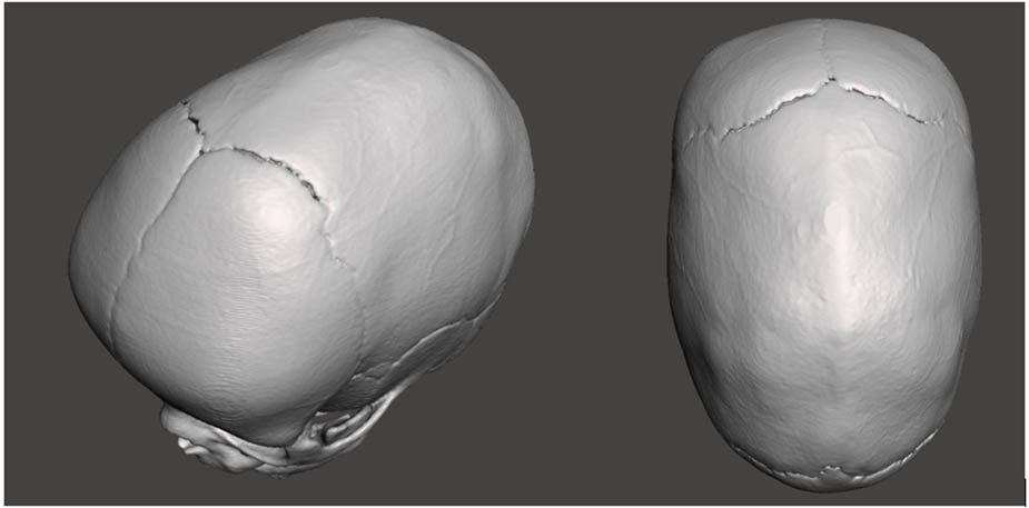
Figure 1
Head CT of a 4-month-old child with congenital craniosynostosis.
The mechanical properties of the cranial bone parts, skull thickness, and the width and length of the osteotomy were constant. In contrast, the spring’s position and diameter (i.e., the force of their interaction) were selected as variables in the simulations.
To prevent rigid body motion and accurately simulate anatomical constraints, a fixed support boundary condition (restricting all six degrees of freedom) was applied to the cranial base, specifically in the region of the occipital and sphenoid bones, mimicking the natural connection to the cervical spine. An additional local fixed support was applied near the sagittal suture. The internal surface of the cranial vault was loaded with an intracranial pressure of P = 2666.4 Pa.
To avoid non-physical stress singularities, the distraction forces were not applied as point loads. Instead, vector loads were uniformly distributed over specifically defined rectangular target faces (surface area of approximately 2 mm²) on the bone edges, strictly replicating the actual contact area of the distraction spring’s footplates. The interactions between continuous bone fragments and sutures were modeled using “Bonded” contact formulations to ensure complete load transfer without surface penetration or separation.
To ensure the reliability of the FE results, a mesh convergence study was performed. The global element size was sequentially refined (e.g., from a standard 5 mm body sizing down to 3 mm). The variation in the maximum equivalent von Mises stress between the accepted mesh (567,232 elements) and the highly refined mesh was found to be less than 4%. This confirmed that the adopted mesh density provided grid-independent and computationally robust results.
The elastic modulus of the parietal bones in skulls with sagittal craniosynostosis varies widely and is primarily determined by individual characteristics. The range of the bone’s elastic modulus can vary from 100 MPa to 3,000 MPa. Poisson’s ratio values can range from 0.2 to 0.3.
Based on data from the literature [17–19] and the authors’ experience, the cranial bone material was defined as isotropic and elastic, with Young’s modulus of 420 MPa and Poisson’s ratio of 0.21.
The thickness of the parietal bones in the constructed model varies in the range from 1.5 mm to 3.5 mm. The width of the osteotomy was 16 mm.
The osteotomy is performed between the coronal and lambdoid sutures to introduce the springs. The distance between the sutures determines the osteotomy length in the simulations.
The action of two distraction springs in different allocations was simulated. The first method, according to the KLS Martin spring manufacturer’s scheme [20], “CranioXpand Cranial springs for the treatment of sagittal craniosynostoses,” places the springs 25 mm from the coronal suture and 55 mm from the lambdoid suture. The second method, proposed by the authors, places the springs farther apart and approximately 10 mm from the lambdoid and coronal sutures.
The distractors used in clinical practice exhibit varying distraction forces, depending on the thickness of the wire from which they are made.
The effect of the forces of all available springs from a given manufacturer was numerically simulated. Numerical simulations were performed for force values: F1 = 4.8 N, F2 = 8 N, and F3 = 13.2 N, originating respectively from springs with diameters: (S1) d1 = 1 mm, (S2) d2 = 1.2 mm, and (S3) d3 = 1.6 mm.
The inner surface was loaded with an intracranial pressure of p = 2666.4 Pa, acting normal to the surface. The support was established in accordance with anatomical conditions, as shown in Figure 2. The FE mesh was generated automatically in the ANSYS Workbench Meshing module. Tetrahedral elements of the TET10 type (ten-node, quadratic shape functions) were used in the analysis, which enable precise mapping of complex geometries. The total number of elements was 567,232, and the number of nodes was 985,292. The mesh quality was assessed as satisfactory based on the quality metric [21–23].
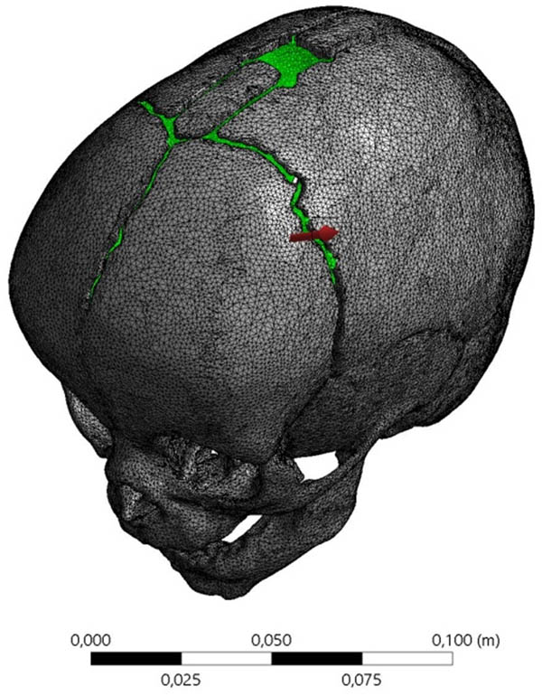
Figure 2
Geometric model of the child’s skull along with the applied mesh.
Numerical studies were conducted for commercial distraction springs, situated according to two concepts: position according to the KLS Martin surgical scheme (KLS), and (AUT) spring allocation proposed by the authors (AUT).
The spring allocation in accordance with the manufacturer’s requirements (KLS) is shown in Figure 3a, whereas the spring allocation (AUT) developed based on the authors’ own research is shown in Figure 3b.
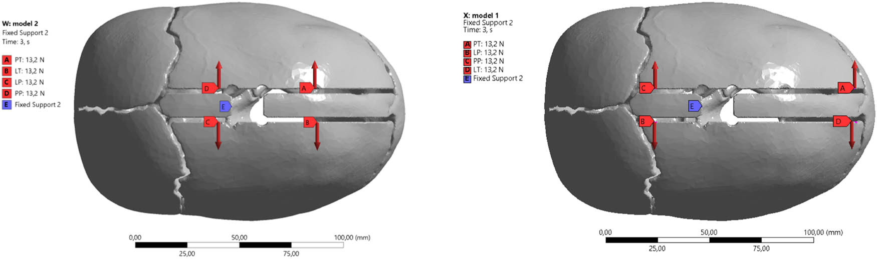
Figure 3
Diagram of the placement of distraction springs: (a) according to the manufacturer’s guidelines (KLS) and (b) proprietary method developed by the authors (AUT).
In ANSYS Workbench, deformation analysis is crucial for understanding how a model responds to applied loads. Total deformation is the complete displacement of a point in the model from its original position due to applied loads. It is a magnitude combining displacements in all directions. It provides a comprehensive view of how much the analyzed model has deformed, regardless of its direction, and is useful for understanding the maximum extent of the deformation.
3. Results
The use of the spring (S1) when situated according to the KLS guidelines causes total, maximum point displacements of the model under loads with a value ẟ KLS1 = 66.125 mm. In contrast, for the same spring, the displacement of the model points is 46% smaller and amounts to ẟ AUT1 = 4.242 mm. The application of springs (S2) and (S3) respectively results in displacements of ẟ KLS2 = 86.769 mm and ẟ KLS3 = 11.587 mm. In all analyzed cases, there was a reduction in the displacement of the analyzed areas of the model; thus, for spring (S2), this value decreased by 53% to ẟ AUT2 = 4.947 mm, while ẟ AUT3 = 5.994 mm, which constitutes 51% of the baseline value.
The total deformation of the skull with the spring allocation according to KLS Martin guidelines, using springs (S1) with a spring force value of F1 = 4.8 N, is shown in Figure 4.
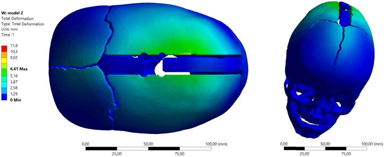
Figure 4
Total deformation of the skull with spring allocation according to the guidelines (KLS1) and the application of spring (S1) with force F1 = 4.8 N.
The total deformation maps confirm the reduction in the values of the analyzed parameters for the skull with the spring allocation proposed by the authors (AUT1). The characteristics of using springs (S1) with a spring force of F1 = 4.8 N are presented in Figure 5.
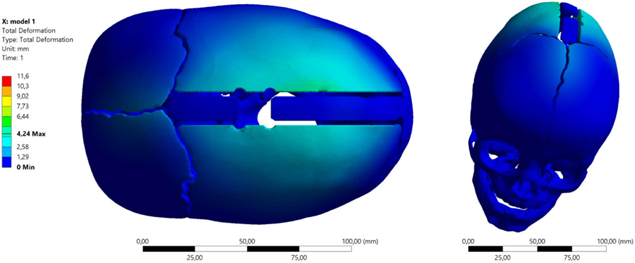
Figure 5
Total deformation of the skull with spring allocation according to the guidelines (AUT1) and the application of spring (S1) with force F1 = 4.8 N.
The total deformation values are respectively ẟ KLS1max = 6.61 mm (average 0.43 mm), while ẟ AUT1max = 4.24 mm (average 0.28 mm).
The total deformation of the skull with spring allocation (S2) according to the KLS Martin guidelines, generating a distraction force with a value of F2 = 8 N, is shown in Figure 6, while with the arrangement of distractors according to the authors’ concept, the characteristics are presented in Figure 7.
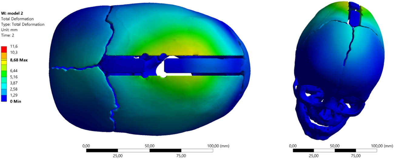
Figure 6
Total deformation of the skull with spring allocation according to the guidelines (KLS2) and the application of spring (S2) with force F2 = 8 N.
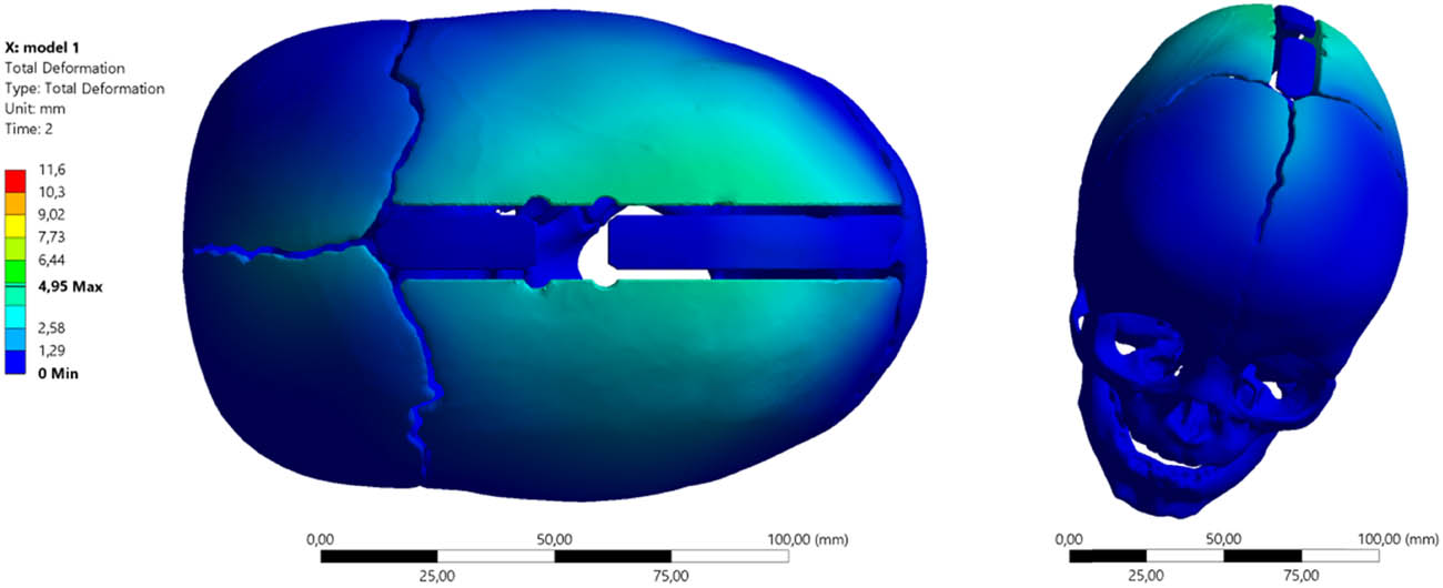
Figure 7
Total deformation of the skull with spring allocation according to the guidelines (AUT2) and the application of spring (S2) with force F2 = 8 N.
The application of springs (S2) and (S3) results in corresponding displacements of ẟ KLS2 = 86.769 mm and ẟ KLS3 = 11.587 mm. In all analyzed cases, there was a reduction in the displacement of the analyzed model areas; thus, for spring (S2), this value dropped by 53%, i.e., ẟ AUT2 = 4.947 mm, whereas ẟ AUT3 = 5.994 mm, which is 51% of the baseline value.
The state of total deformation when using springs (S3) that generate a force of F3 = 13.2 N, with spring allocation according to the guidelines (KLS3), is shown in Figure 8. In contrast, the total deformation characteristic of the cranial bones with spring allocation, as per the guidelines (AUT3), is presented in Figure 9.
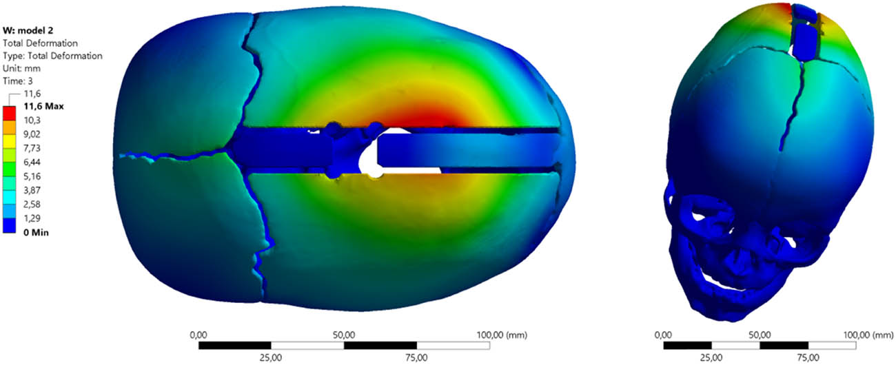
Figure 8
Total deformation of the skull with spring allocation according to the guidelines (KLS3) and the application of spring (S3) with force F3 = 13.2 N.
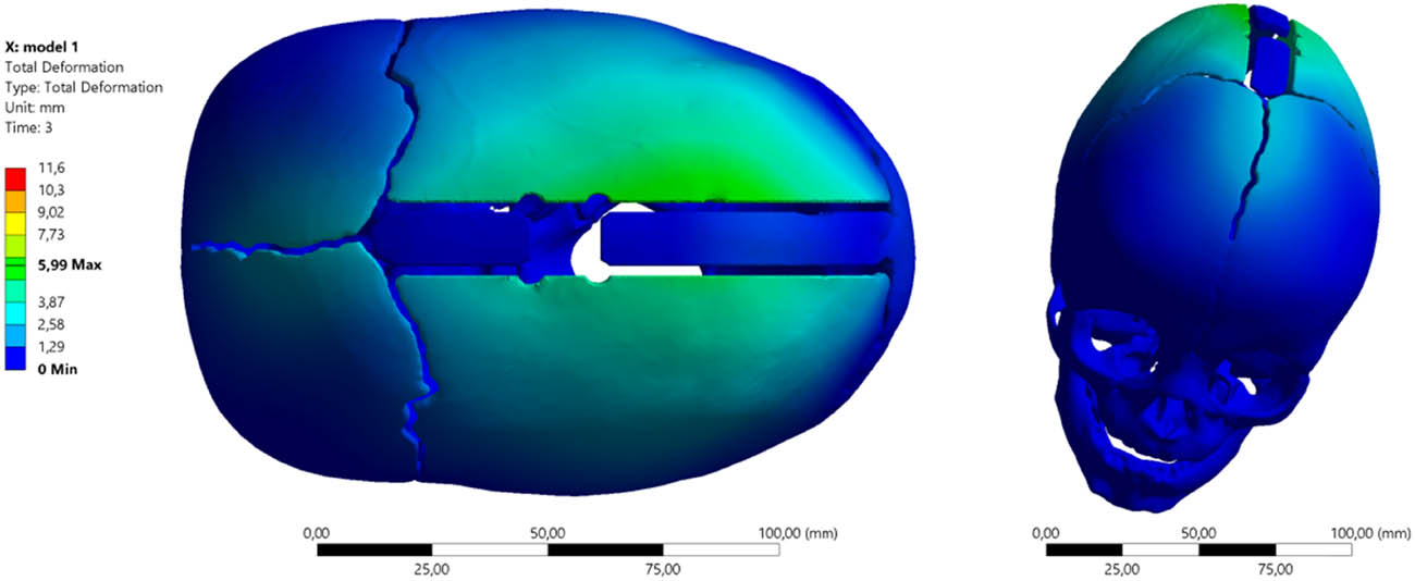
Figure 9
Total deformation of the skull with spring allocation according to the guidelines (AUT3) and the application of spring (S3) with force F3 = 13.2 N.
A summary of the obtained numerical study results is presented in Table 1.
Table 1
Total deformation of the skull using various springs and two analyzed allocations
| Minimum (mm) | Maximum (mm) | Average (mm) | |
|---|---|---|---|
| KLS Martin spring placement scheme | |||
| (S1) 4.8 [N] | 0 | 6.6125 | 0.43141 |
| (S2) 8 [N] | 0 | 8.6769 | 0.58173 |
| (S3) 13.2 [N] | 0 | 11.587 | 0.80421 |
| Authors’ spring placement scheme | |||
| (S1) 4.8 [N] | 0 | 4.242 | 0.28828 |
| (S2) 8 [N] | 0 | 4.947 | 0.35126 |
| (S3) 13.2 [N] | 0 | 5.994 | 0.44944 |
Total deformation combines displacements in all directions, providing a comprehensive picture of the extent of model deformation under loads.
The analysis shows that placing springs according to the KLS scheme generates significantly higher total deformations than the AUT at each force level.
The application of the FEM revealed drastic differences in the spatial distribution of bone tissue displacements. For the highest tested force (13.2 N), the KLS scheme induces a peak displacement of 11.587 mm. For the same force, the AUT arrangement reduces the maximum deformation by almost half, to 5.994 mm.
The above results indicate a phenomenon of strong, localized “bulging” of the bone flap in the KLS scheme. Centrally placed springs act like a point load applied to the center of an elastic plate, causing unnatural, localized deformation. The AUT method (in which the springs are closer to the ends of the osteotomy) distributes energy more evenly across the entire surface of the bone flap. This prevents extreme bending at a single point.
The AUT arrangement results in a more moderate and uniform spatial deformation of the cranial bones, reducing the maximum localized displacements by nearly half at the highest force.
3.1. Equivalent von Mises stress
The distractor (S1) spring allocation (KLS1) results in the skull bones being loaded according to the von Mises equivalent stress maps shown below. The maximum stress value is σ zrKLS1 = 65.152 MPa (Figure 10) and is greater than the values obtained in the distractor system (AUT1) by about 9%, for which the values of reduced stresses are σzrAUT1 = 59.707 MPa (Figure 11).
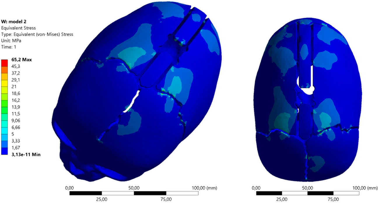
Figure 10
Equivalent von Mises stress maps distractor σzrKLS1 using springs (S1) and spring allocation (KLS1).
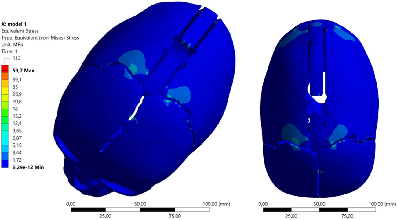
Figure 11
Equivalent von Mises stress maps distractor σzrAUT1 using springs (S1) and spring allocation (AUT1).
The use of distractors (S2) causes an increase in the equivalent stress values σzr(2) in both distractor positions. The nature and magnitude of the equivalent stresses occurring in the cranial bone are shown in Figures 12 and 13. The stress value is σzrKLS2 = 84.487 MPa and is approximately 30% higher than the equivalent stresses when using springs (S1), both for allocation (KLS2) and for allocation (AUT2), where σzrAUT2 = 77.283 MPa.
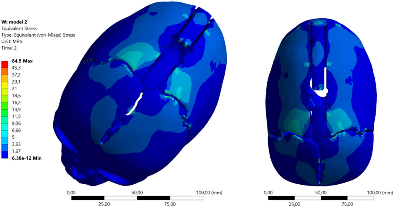
Figure 12
Equivalent von Mises stress maps distractor σzrKLS2 using springs (S2) and spring allocation (KLS2).
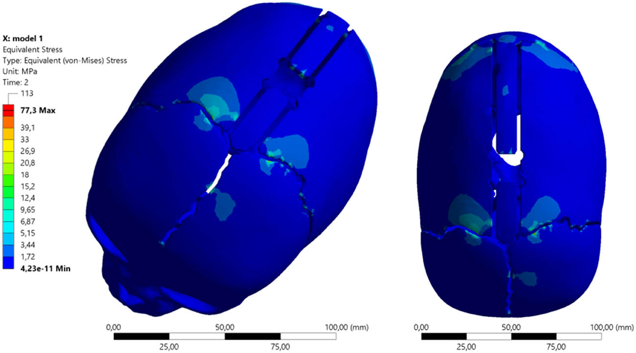
Figure 13
Equivalent von Mises stress maps distractor σzrAUT2 using springs (S2) and spring allocation (AUT2).
The cranial bone stress values across different allocations with the same spring (S2) differ significantly; they are about 9% higher with the allocation recommended by the spring manufacturer.
By analyzing the stress σzr(3) and displacement values, it was determined that the obtained clinical effect would be optimal when using distractors (S3).
The distractor (S3) spring allocation (KLS3) causes cranial bone loads in accordance with the equivalent von Mises stress maps presented below. The maximum stress value is σzrKLS3 = 113.33 MPa and is higher than the values obtained in the distractor arrangement (AUT3) by approximately 6 MPa, for which the equivalent stress values are σzrAUT3 = 106.53 MPa.
The distractor (S3) spring allocation (KLS3) causes cranial bone loads according to the equivalent von Mises stress maps as shown in Figure 14.
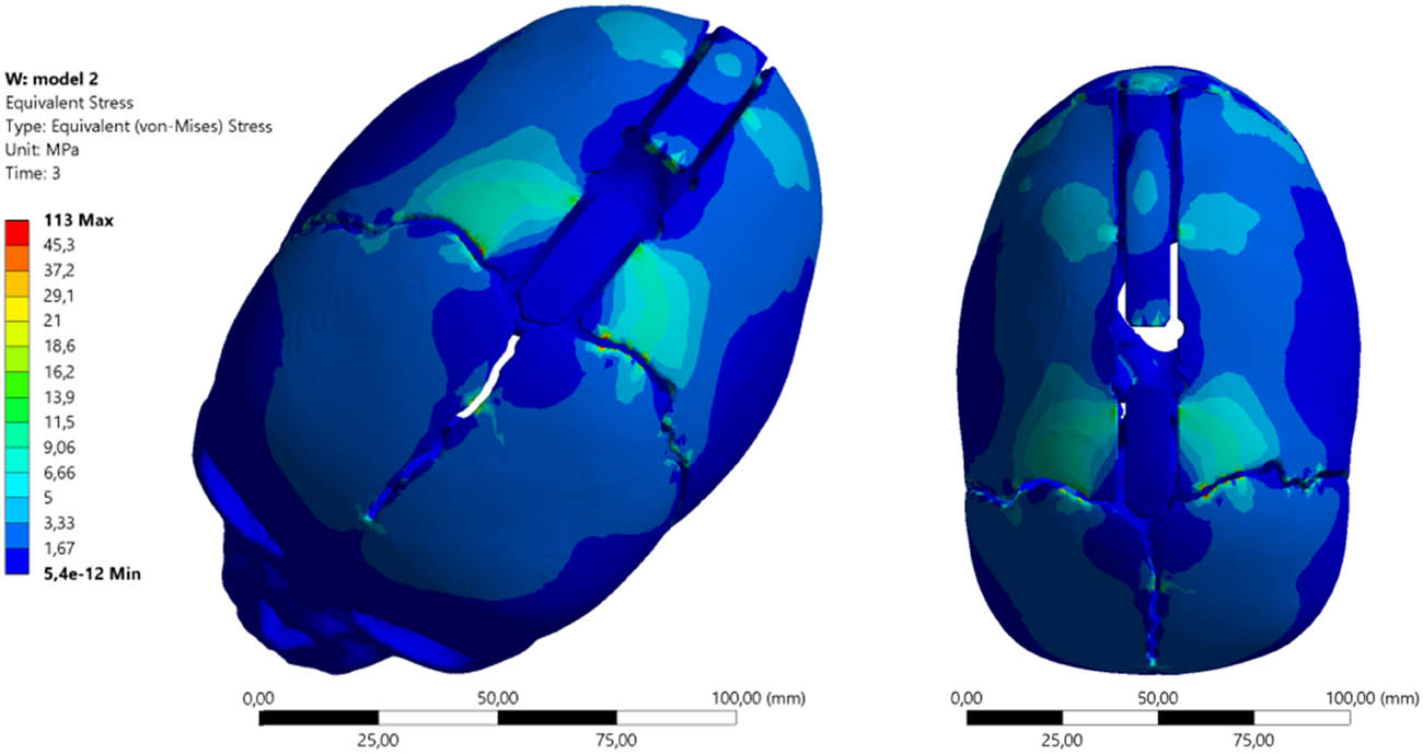
Figure 14
Equivalent von Mises stress maps distractor σzrKLS3 using springs (S3) and spring allocation (KLS3).
The distractor (S3) spring allocation (AUT3) causes cranial bone loads according to the equivalent von Mises stress maps as shown in Figure 15.
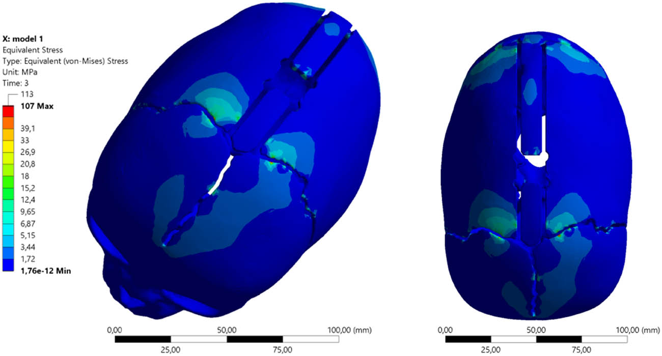
Figure 15
Equivalent von Mises stress maps distractor σzrAUT3 using springs (S3) and spring allocation (AUT3).
A summary of the numerical test results obtained for the analyzed model is presented in Table 2.
Table 2
Summary of numerical test results obtained for the analyzed model
| Minimum (MPa) | Maximum (MPa) | Average (MPa) | |
|---|---|---|---|
| KLS Martin spring placement scheme | |||
| (S1) 4.8 [N] | 3.1343 × 10⁻¹¹ | 65.152 | 0.37997 |
| (S2) 8 [N] | 6.3834 × 10⁻¹² | 84.487 | 0.50891 |
| (S3) 13.2 [N] | 5.4038 × 10⁻¹² | 113.33 | 0.70371 |
| Authors’ spring placement scheme | |||
| (S1) 4.8 [N] | 6.2886 × 10⁻¹² | 59.707 | 0.2639 |
| (S2) 8 [N] | 4.2252 × 10⁻¹¹ | 77.283 | 0.32232 |
| (S3) 13.2 [N] | 1.76e × 10–12 | 106.53 | 0.41685 |
Equivalent stress analysis is critical because comparing them with the bone’s yield strength values allows for predicting areas of potential fracture or damage. The authors’ placement consistently exhibits lower maximum and average stress values in the bone structure.
In FEM analysis, von Mises stresses are a direct indicator of the risk of material structure failure. The simulation showed that at the maximum force of 13.2 N, the KLS Martin method produces peak bone stresses of 113.33 MPa. The AUT method clearly lowers these values to 106.53 MPa.
The solution proposed by the authors (springs placed closer to the coronal and lambdoid sutures) appears to be more biomechanically advantageous in the analyzed case. It suggests the potential for significantly smaller localized deformations (both total and directional) and lower stresses in the parietal bones when applying the same forces. This provides higher procedural safety and a lower risk of bone damage (fracture) at the sites of force application.
The numerical studies performed also allowed for determining the change in skull shape that can be achieved as a result of applying individual springs in various allocations. This phenomenon is essential for optimizing the process of cranial distraction and brain decompression, as well as obtaining an optimal visual effect. In order to select the optimal treatment process, directional displacements were analyzed.
3.2. Directional deformation results for (S3) and spring allocation (KLS3)
The complex shape of the cranial bones implies that the application of distractors will induce an asymmetrical spreading of the bones. Applying the springs in the central part of the skull, according to the scheme (KLS3), would cause the cranial vault to stretch in the range of 8.17–10.2 mm. In the frontal and occipital regions, the deformations would not be as pronounced, meaning the neurosurgeon’s intended skull shape would not be optimal (Figure 16).
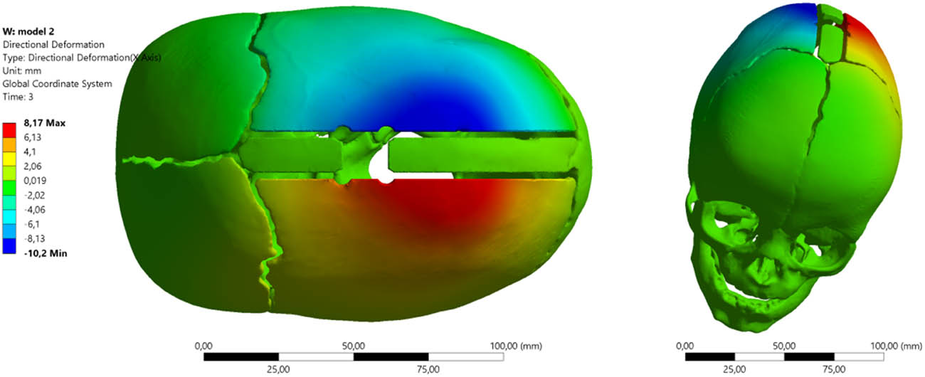
Figure 16
Cranial distraction using springs (S3) and allocation (KLS3).
The use of distractors (S3) allocated closer to the coronal and lambdoid sutures changes the shaping characteristics of the young patient’s skull (Figure 17). Directional deformation X is not as large as in the case of (KLS3); however, in such an arrangement, greater stretching occurs not in the central part of the skull, but in the region of the sutures, making the head rounder. With the allocation (AUT3) of spring (S3), cranial distraction occurs within the range from 4.15–5.26 mm.
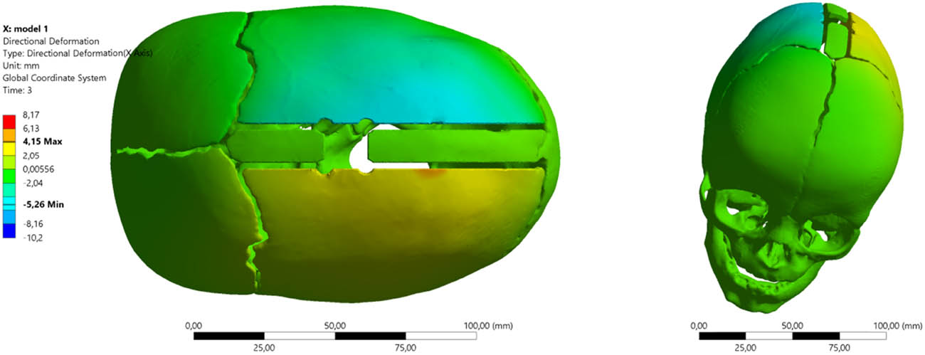
Figure 17
Cranial distraction using springs (S3) and allocation (AUT3).
Intraoperative measurements are significant, and the database developed over years of implementing the treatment process enables proper programming of numerical studies.
It should be noted that a child’s cranial bones are very thin (in the analyzed model, from 1.5 to 3.5 mm) and are characterized by relatively low stiffness (Young’s modulus assumed at 420 MPa). Infant bone, despite its elasticity, has a specific strength limit. Exceeding the local yield point can result in microfractures, bone resorption under metal pressure, or dangerous penetration of the spring through the bone into the intracranial space. The significant reduction in maximum stresses by the authors’ arrangement drastically increases the safety margin of the procedure.
By analyzing the stress and displacement values and taking into account the young patient’s extremely dolichocephalic head, it was determined that the clinical effect achieved would be too small when using distractors (S1). Optimization of the skull shape should, according to the planned treatment process, shape the skull toward brachycephaly. Numerical simulations allowed for determining that, as a result of the undertaken treatment utilizing distractors allocated closer to the coronal and lambdoid sutures, the skull shape should be formed as shown in Figure 18.
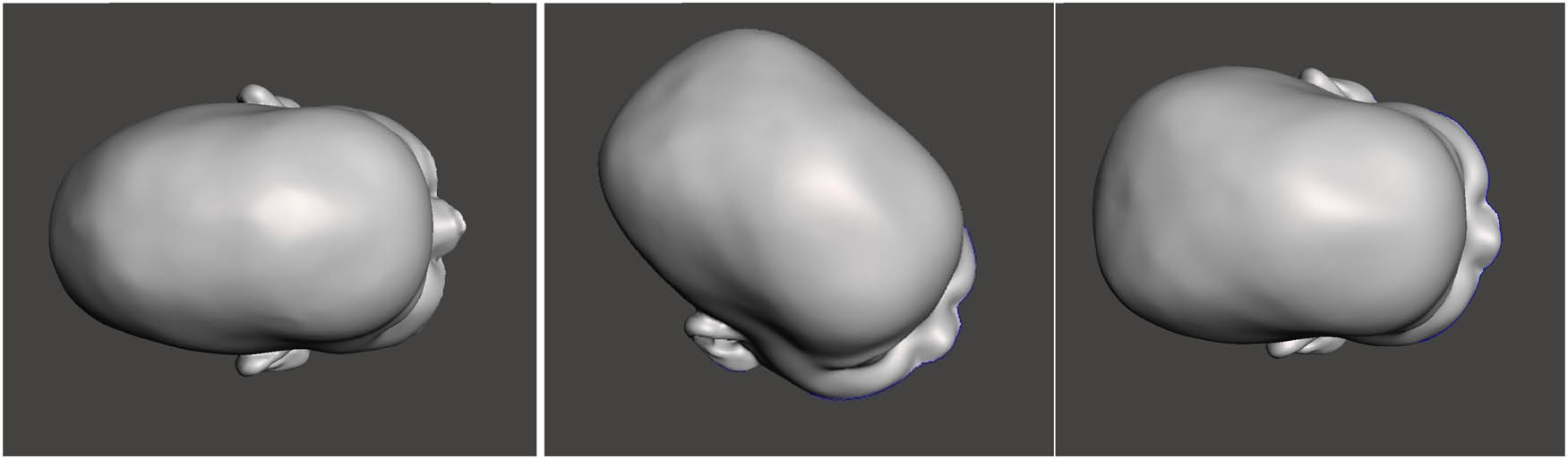
Figure 18
Simulated skull shape after the distraction process and spring allocation (AUT3): (a) skull before surgery, (b) application of distractor (S2), and (c) application of distractor (S3).
3.3. Verification of numerical studies against clinical trials
As a result of the numerical analysis, the Operating Team, led by Prof. D. Larysz, decided to use distraction springs (S3) with a distraction force of F3 = 13.2 N and a spring allocation according to the (AUT3) scheme. The treatment process lasted 24 weeks and proceeded without complications.
As a result of the distraction process, the planned change in skull shape occurred. Clinical results were verified against three-dimensional images using a 3D scanner. Adopting this diagnostic method allows for genuinely determining the skull shape after the treatment. It does not expose the patient to the need for ionizing examinations, which is particularly important in such a young organism after a severe bone remodeling process.
3.3.1. Comparative analysis of cranial geometry before and after surgery
The analysis was performed in the Geomagic Design X reverse engineering environment using the Accuracy Analyzer tool. Two 3D models (surface scans) were superimposed: the reference model (preoperative state) and the tested model (postoperative state).
The generated color map (heatmap) illustrates the geometric deviations between the two surfaces.
Interpreting the deviation map allows for isolating the areas that underwent correction, with individual colors presenting the intensity of the change and the deviation map with color gradation, where
− Green color: Indicates areas of geometric conformity (within the specified tolerance). These are the base points that did not undergo significant displacement (visible mainly at the base of the skull, around the ears, and on the neck).
− Colors from yellow to red: Indicate areas where the geometry increased in volume following distraction.
− Colors from blue to dark blue: Indicate areas where the geometry following the treatment process is below the reference geometry (reduction/flattening).
3.3.2. Detailed analysis of anatomical changes
Parietal zone and top of the head – intense red and yellow colors dominate in the upper and posterolateral parts of the skull. This indicates a significant increase in the cranial vault’s height and volume. This is a typical effect of craniosynostosis correction, which aims to create space for brain development. The postoperative model is clearly convex in this area relative to the flattened preoperative model.
Frontal and occipital zone – blue zones are visible. This suggests a remodeling of the curvature in these areas. Depending on the adopted alignment (basing), this may signify a relative retraction of these surfaces or a change in their inclination angle to achieve a more spherical head shape.
The overall shape was significantly corrected; a transformation from an elongated shape (e.g., scaphocephaly) to a more rounded, proportional shape is evident.
Based on measurements verified by clinical trials, the maximum deviation was approximately 28.2 mm, demonstrating a significant scale of surgical intervention and a substantial extent of geometric cranial remodeling (Figure 19).
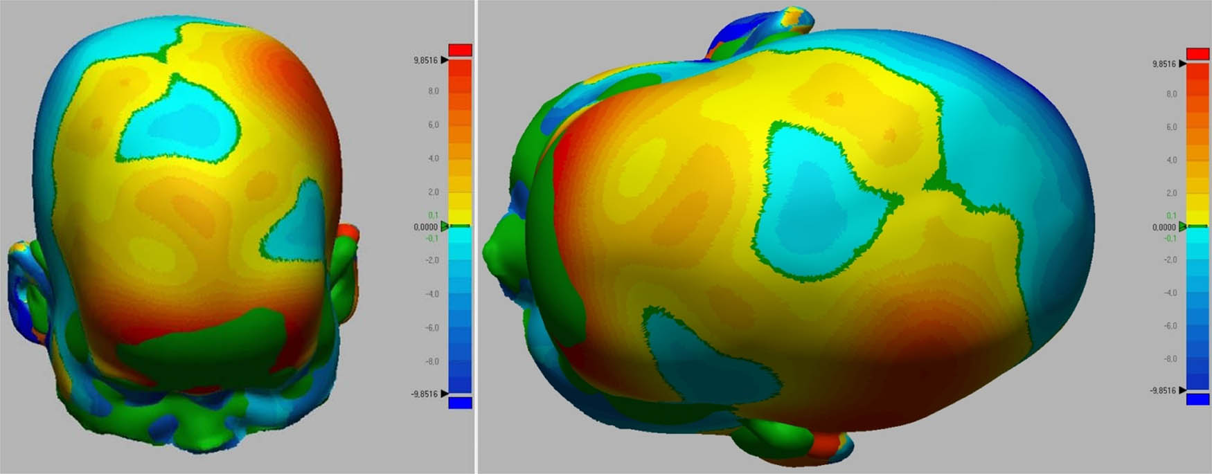
Figure 19
Skull shape deviation maps: (a) before surgery, and (b) after the treatment process.
The surgical procedure led to a significant volumetric correction. The greatest changes (volume increase) occurred within the parietal bones, which resulted in an improvement of the cephalic index and the achievement of a more correct curvature of the cranial vault, as shown in Figure 20.
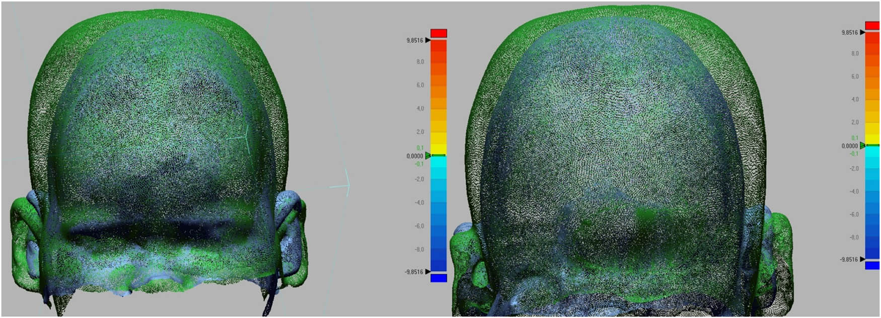
Figure 20
Change in skull shape as a result of the treatment process.
It should be noted that while the primary goal of the surgery is to increase ICV for brain development, direct post-operative measurement of the brain or ICV was not performed. To strictly limit the infant’s exposure to ionizing radiation, post-operative CT scanning was deliberately omitted in favor of non-invasive 3D optical surface scanning. Therefore, the significant increase in external cranial vault volume and the positive geometric remodeling captured by the 3D scanner serve as a safe and reliable clinical proxy indicating successful spatial decompression of the cranial cavity.
4. Conclusion
The application of the novel method proposed by the authors (AUT), which involves wider spacing of the distraction springs, results in a different cranial shape compared with springs positioned according to the manufacturer’s guidelines (KLS). Cranial distraction occurs near the coronal and lambdoid sutures, making the patient’s head rounder, and the cephalic vault asymmetry index falls within the brachycephalic range, which is more beneficial for proper brain development and aesthetic qualities. The wider spring spacing in the authors’ scheme results in significantly smaller asymmetric directional displacements (less “stretching” on the X-axis) than in the (KLS) scheme. Changing the spring spacing reduces the equivalent stress during the critical stretching period, thereby limiting the risk of bone tissue damage, bone fractures, and overload osteolysis.
The skull-stretching process is extended over time, which is also beneficial from a treatment perspective. Sudden decompression of the brain and rapid stretching of bone tissues can cause various adverse phenomena, as well as very intense pain sensations. Spreading the cranial bone stretching process over time and the slow separation of the cranial bones do not affect the rate of bone cell proliferation or the speed of fusion in any way.
Based on the conducted numerical studies, it was also concluded that the design of craniosynostosis treatment planning can be configured to introduce personalized force into areas that are critical from the perspective of shaping the cranial bones; this allows for the offloading of areas with bone defects or complex tissue anomalies, while increasing loads in areas where the bone must be displaced to achieve the planned clinical effect. The allocation of springs and the distraction force should be tailored to the skull shape, accounting for a highly complex and often pathologically altered bone structure. Achieving a clinical effect that is sustained over time by reducing stress values can also be significant, because the bone remodeling process can be designed so that bones multiply along the direction of principal stresses, thereby allowing for the optimization of the skull shape envisioned by the neurosurgeon.
The use of a personalized skull model derived from the patient’s CT, reflecting the shape and size of the skull and accounting for bone strength parameters and intracranial pressure, enables highly precise planning of the final outcome – the result of the treatment process.
The team’s planning for further research focuses on evaluating the magnitude and nature of bone deformations and stresses in various allocations along the cutting line, using different spring configurations. The current state of the art does not allow for the use of springs with a personalized, highly precisely selected distraction force, which constitutes another design and technological challenge that could significantly improve the treatment process for children with this severe congenital disease.
4.1. Limitations
While the developed patient-specific numerical model provides significant clinical insights, certain methodological limitations must be acknowledged. The cranial bone was assumed to be a homogeneous, isotropic, and linearly elastic material (E = 420 MPa, ν = 0.21). In reality, infant cranial bone is a thin-walled, anisotropic, and biologically variable structure with distinct cortical and cancellous layers. However, this simplification is a widely accepted standard in macro-scale biomechanical modeling, primarily because extracting patient-specific microstructural data (such as collagen fiber orientation) from routine clinical CT scans is not feasible.
To address this uncertainty, a material sensitivity analysis was conducted. Varying the Young’s modulus over a wide physiological range (e.g., from 200 to 800 MPa) resulted in proportional scaling of total deformations and localized stress concentrations. Most importantly, the comparative biomechanical trends – specifically, that the authors’ proposed spring allocation (AUT) consistently reduces peak stresses and yields a more favorable clinical shape compared to the manufacturer’s scheme (KLS) – remained stable and independent of the exact elastic modulus value.
The most significant limitation of this study is that it is based on a single patient-specific numerical model and one corresponding clinical case. Therefore, the findings regarding the biomechanical advantages, increased safety margin, and shape optimization of the proposed spring allocation (AUT) must be interpreted as a proof-of-concept and a biomechanical hypothesis rather than definitive proof of widespread clinical superiority. While the initial results are highly promising, further clinical trials involving a larger cohort of patients are necessary to statistically validate these observations and establish generalized clinical guidelines.
Author contributions
Arkadiusz Szarek: Preparation of the research program, execution of research, statistical analysis, interpretation of data, preparation of the manuscript, and obtain financing; Piotr Paszta: Execution of research, interpretation of data, and preparation of the manuscript; Dawid Larysz: Preparation of the research program, interpretation of data, clinical trials, and obtain financing; Patrycja Larysz: Preparation of the research program, interpretation of data, clinical trials, and carrying out this work.