
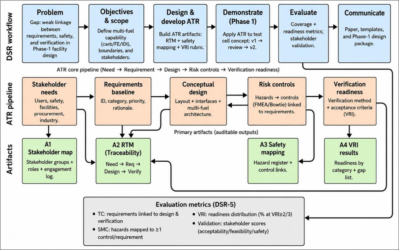
Fig. 1.
Assurance–Traceability–Risk (ATR) conceptual model embedded within the Design Science Research (DSR) workflow for Phase 1 development of a multi-fuel aircraft reciprocating engine test cell.
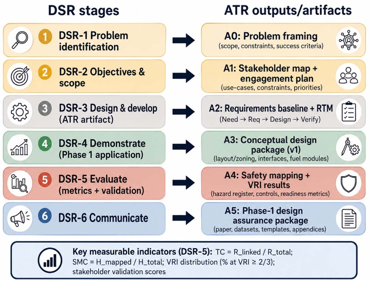
Fig. 2.
Design Science Research (DSR) stages and corresponding Assurance–Traceability–Risk (ATR) outputs/artifacts for Phase 1 of the multi-fuel reciprocating engine test cell project.
Table 1.
Stakeholder-Driven Requirements Baseline by Category, Priority, and Source.
| Requirement category | No. of requirements | Main priority level | Main contributing source groups | Typical requirement focus |
|---|---|---|---|---|
| Multi-configuration fuel architecture | 7 | P1–P2 | Test-cell operators; engine-shop personnel; external training/industry experts | Carb/EFI/DI compatibility, modular/separate fuel routing, supply/return lines, filters, regulators, selectors, shutoff, compartmentalized fuel systems |
| Controls/interlocks and operational safety | 7 | P1 | Test-cell operators; engine-shop personnel; external experts | E-stop, fuel shutoff, master switch, fire response, safety barriers, signage, configuration safety controls |
| Instrumentation/DAQ and calibration | 8 | P1–P2 | Instrumentation/calibration personnel; electrical/avionics personnel; external experts | RPM, oil pressure/temperature, CHT, EGT, fuel pressure/flow, MAP, analog/digital display, logging, calibration control |
| Facility ventilation/exhaust/noise control | 7 | P1–P2 | Test-cell operators; external experts; safety/compliance contributors | Fresh-air supply, exhaust routing, negative pressure, CO/fire considerations, heat protection, muffler/silencer, noise control |
| Structural/layout and utilities | 5 | P1–P2 | Engine-shop personnel; test-cell operators; electrical support | Engine geometry, structural loads, engine mounting, high ceiling, propeller guard, grounding, electrical readiness |
| Operations/human factors and maintenance procedures | 5 | P2–P3 | Operators; maintenance personnel; quality/compliance contributors | Checklists, routine inspection, pre-start procedures, standard run-in profile, cable/harness marking, coordination protocols |
| Verification/compliance readiness | 3 | P1 | Test-cell operators; external experts; quality/compliance contributors | Frozen requirements, final drawings/calculations, safety/compliance review, design-ready acceptance criteria |
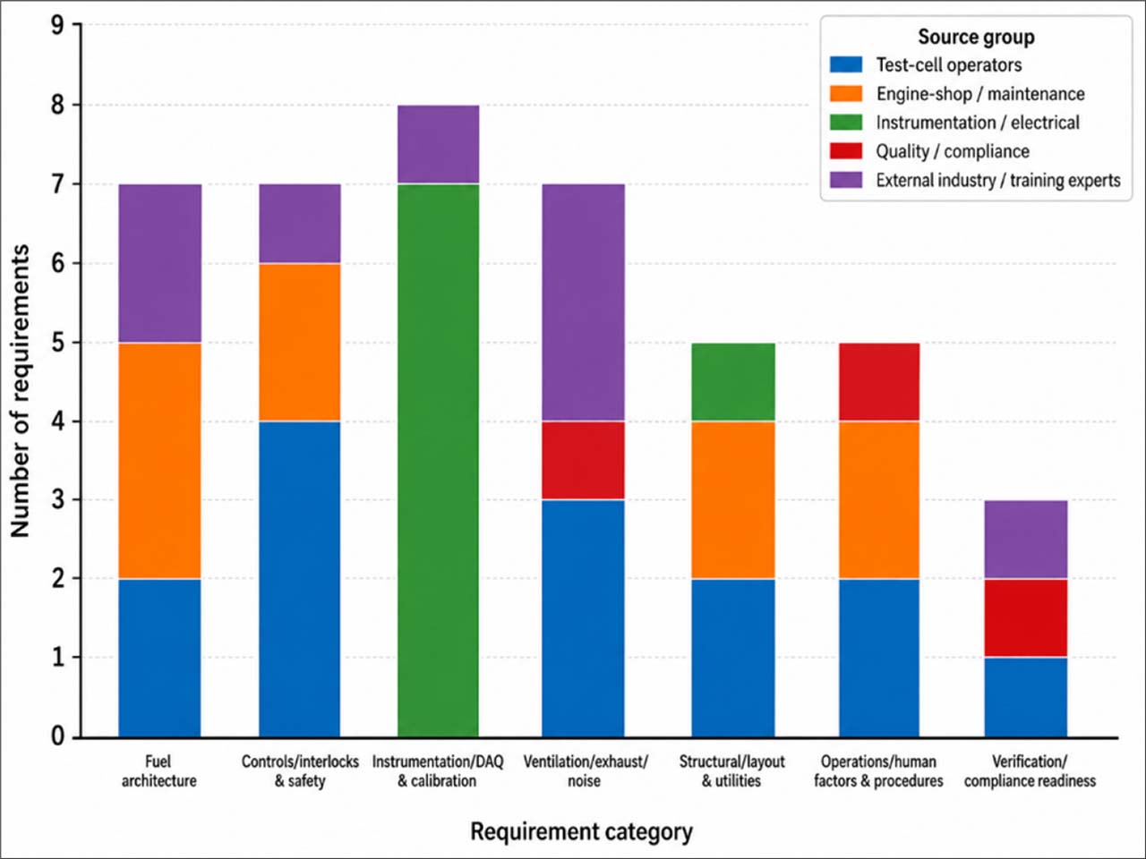
Fig. 3.
Distribution of stakeholder-derived requirements by category and source group.
Table 2.
Conceptual Design Outputs for Multi-Fuel Compatibility.
| Design area | Carbureted configuration | EFI configuration | DI configuration | Conceptual design output |
|---|---|---|---|---|
| Fuel routing | Gravity/feed line, pump, filter, selector, shutoff | Pump, filter, supply/return line, pressure regulation, shutoff | Reserved high-pressure routing provision, fittings, barriers, inspection points | Modular/compartmentalized fuel-routing panel with separated paths per configuration |
| Instrumentation/DAQ | RPM, oil pressure/temp, CHT, EGT, MAP | RPM, oil pressure/temp, CHT, EGT, MAP, fuel pressure/flow | Expanded fuel pressure/flow monitoring and configuration-specific DAQ points | Hybrid analog–digital instrumentation with calibration-ready DAQ and logging |
| Safety interlocks | E-stop, fuel shutoff, master switch, fire response | E-stop, fuel shutoff, electrical isolation, checklist control | E-stop, fuel shutoff, pressure-related safeguards, enhanced inspection control | Common safety-interlock layer with configuration specific permissives |
| Purge/venting | Ventilation for fumes, heat, and exhaust | Ventilation for fuel vapor, heat, and exhaust | Enhanced purge/venting provision before DI adoption | Dedicated ventilation/exhaust system with negative-pressure and backpressure considerations |
| Utilities | Engine mounting, basic electrical supply, grounding | Electrical/DAQ support, grounding, sensor wiring | Reserved utility capacity for advanced controls and higher monitoring demand | Utility-ready layout for power, grounding, DAQ, cooling, ventilation, and maintenance access |
| Layout logic | Engine bay + fuel panel + operator control | Engine bay + fuel/control panel + DAQ interface | Engine bay with reserved DI-safe routing and control provisions | Separated zones for engine bay, modular fuel/control panels, DAQ/control room, exhaust path, and safety access |
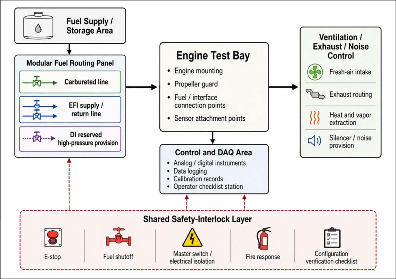
Fig. 4.
Conceptual layout logic for multi-fuel compatibility showing separated fuel-routing paths, engine test bay, DAQ/control area, ventilation/exhaust system, and shared safety-interlock layer.
Table 3.
RTM Traceability Coverage by Requirement Category.
| Requirement category | Total requirements | With source link | With design-feature link | With verification-method link | Trace-complete requirements | Trace-complete (%) |
|---|---|---|---|---|---|---|
| Multi-configuration fuel architecture | 7 | 7 | 7 | 6 | 6 | 85.70 |
| Controls/interlocks and operational safety | 7 | 7 | 7 | 7 | 7 | 100.00 |
| Instrumentation/DAQ and calibration | 8 | 8 | 8 | 7 | 7 | 87.50 |
| Facility ventilation/exhaust/noise control | 7 | 7 | 6 | 6 | 6 | 85.70 |
| Structural/layout and utilities | 5 | 5 | 5 | 4 | 4 | 80.00 |
| Operations/human factors and maintenance procedures | 5 | 5 | 4 | 3 | 3 | 60.00 |
| Verification/compliance readiness | 3 | 3 | 2 | 2 | 1 | 33.30 |
| Total | 42 | 42 | 39 | 35 | 34 | 81.00 |
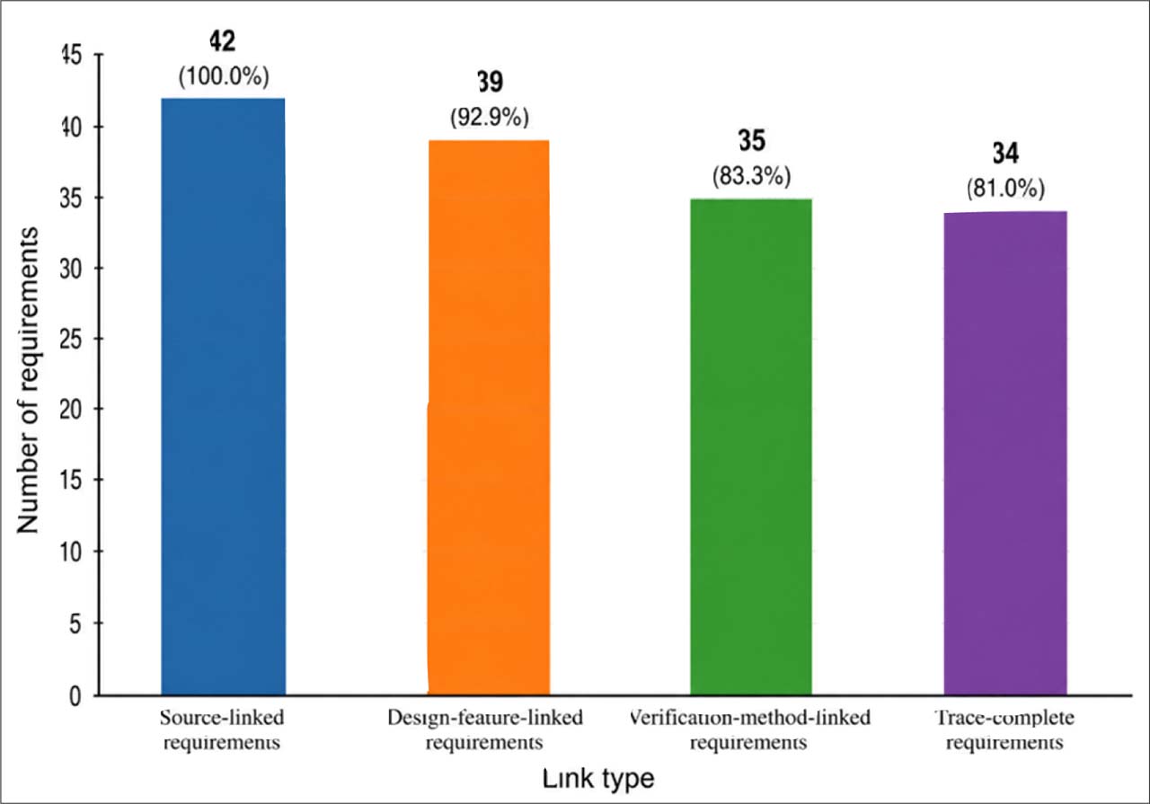
Fig. 5.
RTM Coverage by Link Type.
Table 4.
Hazard-Control Mapping Summary.
| Hazard category | No. of hazard scenarios | Main hazards identified | Preventive controls mapped | Mitigative controls mapped | Coverage status | High-priority gaps |
|---|---|---|---|---|---|---|
| Fuel handling and configuration changeover | 4 | Leakage, contamination, incorrect configuration, fuel-routing mismatch | Modular/separated routing, fuel selector, filters, pressure regulator, shutoff valve, configuration checklist | Immediate repair/maintenance response, routine inspection, isolation of affected line | Strong | DI high-pressure routing, fittings, barriers, and inspection protocol require further verification |
| Electrical/control-system faults | 3 | Short circuit, control malfunction, unsafe start/run condition | Master switch, electrical isolation, harness marking, checklist verification | E-stop, fuel shutoff, emergency response | Strong | Detailed E-stop logic and interlock verification still needed |
| Instrumentation, DAQ, and calibration | 3 | Inaccurate readings, limited sensor coverage, poor data traceability | Calibration schedule, in-date instrument checks, minimum sensor suite, analog/digital display | Reasonableness checks, maintenance of instruments, data review | Moderate to strong | Alarm thresholds, DAQ logging, and traceable digital records require refinement |
| Ventilation, exhaust, heat, and noise | 4 | Fuel vapor accumulation, poor exhaust routing, heat exposure, excessive noise | High-capacity ventilation, fresh-air intake, exhaust routing, silencer/noise provision, CO/fire consideration | Fire guard, heat/vapor extraction, community/safety consultation | Moderate | Negative pressure, backpressure limits, CO monitoring, and noise-control design need formal calculation |
| Mechanical/structural hazards | 2 | Engine mounting failure, propeller exposure, vibration/structural load risk | Engine geometry checks, structural load review, propeller guard, high-ceiling provision | Physical guarding, controlled test bay access | Moderate to strong | Structural calculations and propeller-guard dimensions require Phase 2 confirmation |
| Human-factor/procedural risks | 2 | Checklist omission, poor contractor–proponent coordination, setup error | Pre-start checklist, standard run-in procedure, stakeholder coordination, configuration marking | Review/correction through disposition log and design review | Moderate | Formal configuration-control procedure and responsibility matrix needed |
| Total | 18 | — | 16 hazards with preventive/mitigative control linkage | 14 hazards with both preventive and mitigative controls | 88.9% mapped; 77.8% dual-control coverage | DI, ventilation/exhaust, DAQ alarms, and verification criteria remain priority gaps |
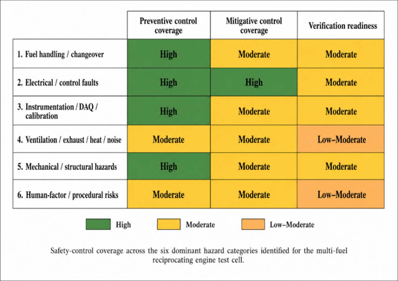
Fig. 6.
Safety-control coverage heat map.
Table 5.
Verification Readiness Index Results by Requirement Category.
| Requirement category | Total requirements | High readiness | Moderate readiness | Low readiness | Mean VRI score | Readiness interpretation |
|---|---|---|---|---|---|---|
| Multi-configuration fuel architecture | 7 | 5 | 2 | 0 | 82.9 | High |
| Controls/interlocks and operational safety | 7 | 6 | 1 | 0 | 90.0 | High |
| Instrumentation/DAQ and calibration | 8 | 5 | 3 | 0 | 83.8 | High |
| Facility ventilation/exhaust/noise control | 7 | 2 | 4 | 1 | 72.9 | Moderate |
| Structural/layout and utilities | 5 | 2 | 2 | 1 | 76.0 | Moderate |
| Operations/human factors and maintenance procedures | 5 | 1 | 3 | 1 | 66.0 | Moderate |
| Verification/compliance readiness | 3 | 0 | 2 | 1 | 61.7 | Moderate–low |
| Total / Overall | 42 | 21 | 17 | 4 | 78.2 | Moderate–high |
Table 6.
VRI Sensitivity Analysis Under Alternative Weighting Scenarios.
| Scenario | Verification method | Acceptance criterion | Evidence source | Responsibility | Stage/timing | Overall VRI | Readiness band | Interpretation |
|---|---|---|---|---|---|---|---|---|
| Baseline equal weights | 0.2 | 0.2 | 0.2 | 0.2 | 0.2 | 78.2 | Moderate–high | Primary reported equal-weight VRI |
| Verification-execution emphasis | 0.3 | 0.3 | 0.15 | 0.15 | 0.1 | 77.6 | Moderate–high | Tests emphasis on verification method and acceptance criteria |
| Evidence-assurance emphasis | 0.15 | 0.15 | 0.3 | 0.2 | 0.2 | 80.2 | High | Tests emphasis on evidence source and assurance support |
| Governance emphasis | 0.15 | 0.15 | 0.2 | 0.25 | 0.25 | 77.7 | Moderate–high | Tests emphasis on responsibility and verification timing maturity |
| Method-and-criteria reduced | 0.15 | 0.15 | 0.25 | 0.25 | 0.2 | 78.8 | Moderate–high | Tests reduced dependence on method and criteria |
[i] Note. The baseline equal-weight scenario uses the same requirement-level VRI calculation reported in Table 5; therefore, both tables report the same overall VRI of 78.2/100. Alternative scenarios apply different attribute weights for sensitivity analysis.
Table 7.
Verification Readiness Gaps and Phase 2 Action Priorities.
| Readiness gap | Affected requirement area | Reason for lower readiness | Required Phase 2 action |
|---|---|---|---|
| DI-specific fuel-system provisions | Multi-configuration fuel architecture | Limited direct DI test-cell experience among experts; high-pressure routing and fittings not yet technically specified | Conduct supplier/technical consultation, pressure-rating review, and DI-specific safety validation |
| Ventilation/exhaust performance | Facility ventilation/exhaust/noise control | Ventilation need was strongly identified, but airflow, negative pressure, heat load, and backpressure values remain uncalculated | Perform ventilation/exhaust engineering calculations and define acceptance criteria |
| Noise and heat control | Facility ventilation/exhaust/noise control | Noise and heat concerns were identified, but control performance remains conceptual | Specify silencer/muffler, heat shielding, and noise-control performance targets |
| E-stop and interlock logic | Controls/interlocks and operational safety | Safety functions were identified as critical, but logic sequence and response criteria remain preliminary | Develop interlock logic diagram and verification test procedure |
| DAQ alarms and digital logging | Instrumentation/DAQ and calibration | Sensor suite was identified, but alarm thresholds, sampling/logging, and traceability rules need refinement | Define DAQ specification, calibration traceability, alarm thresholds, and data-recording protocol |
| Structural and propeller-guard confirmation | Structural/layout and utilities | Mounting, high ceiling, and propeller guard were identified, but dimensions and load calculations remain pending | Complete structural/load review and guard-spacing verification |
| Configuration-control procedure | Operations/human factors and maintenance procedures | Checklist use was emphasized, but formal responsibility and configuration-change workflow remain incomplete | Develop configuration-control checklist, responsibility matrix, and changeover verification form |
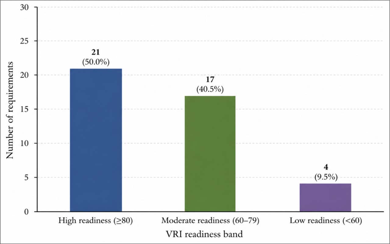
Fig. 7.
VRI Score Distribution by Readiness Band.
Table 8.
Technical Expert Feasibility Validation Results by Configuration.
| EFV metric | Carbureted | EFI | DI | Interpretation |
|---|---|---|---|---|
| EFV1. Feasibility rating | 4.5 / 5.0 | 4.3 / 5.0 | 2.8 / 5.0 | Carbureted and EFI are highly feasible; DI is conditionally feasible |
| EFV2. Inter-expert convergence | High | High | Low–moderate | Agreement was strongest for existing carb/EFI capability and weaker for DI |
| EFV3. Critical issue density | Low | Moderate | High | DI generated the most unresolved technical concerns |
| EFV4. Comment closure | 7/7 comments closed 100%) | 6/7 comments closed (86%) | 4/7 comments closed (57%) | Carbureted and EFI comments were mostly resolved; DI retained more unresolved issues requiring Phase 2 verification |
| Overall readiness judgment | Ready for detailed design | Ready for detailed design | Requires further technical validation | DI should remain a reserved/future-compatible provision |
[i] Note. EFV1 values are mean expert feasibility ratings based on a five-point scale: 1 = not feasible; 2 = weak feasibility; 3 = conditionally feasible; 4 = feasible; 5 = highly feasible. EFV4 reports the number of expert comments closed out of the total expert comments recorded for each configuration; percentages are rounded to whole numbers because the denominator is small.
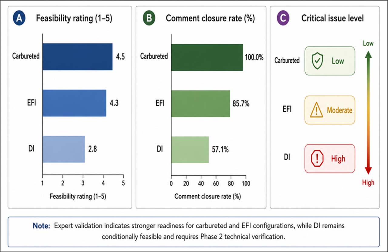
Fig. 8.
Technical Expert Feasibility Profile by Configuration.
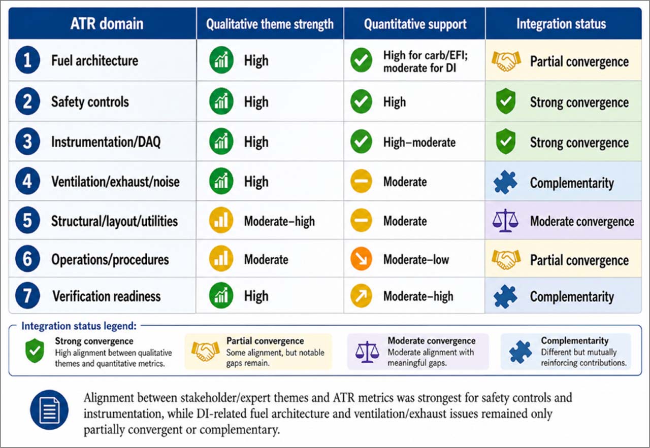
Fig. 9.
Integrated ATR Convergence Matrix.
Appendix Table A1.
Positioning of ATR Relative to Established Systems Engineering Approaches
| How ATR complements it | Difference from ATR | Typical artifacts | Main purpose | Approach |
| ATR prepares early requirements, risks, and verification evidence that can later inform MBSE models. | ATR is not a full model-based engineering environment and does not create executable system models. | Architecture models, behavior diagrams, interface models, simulation or verification models. | Formal modeling of system architecture, behavior, interfaces, and verification logic. | Model-Based Systems Engineering (MBSE) |
| ATR provides accessible Phase 1 traceability before detailed SysML modeling is practical. | ATR uses an RTM-centered traceability structure rather than a formal SysML model. | SysML requirement diagrams, block diagrams, and <<satisfy>>, <<verify>>, and <<trace>> links. | Formal linking of requirements, blocks, interfaces, constraints, and test cases. | SysML-based traceability |
| ATR creates an initial evidence spine that can later become part of a digital thread. | ATR is limited to pre-construction evidence organization and does not yet span the full lifecycle. | Connected lifecycle data, configuration records, design evidence, and operational records. | Lifecycle data continuity from requirements to design, production, operation, and maintenance. | Digital Thread |
| ATR defines the requirements, controls, and verification evidence needed before a future test-cell twin can be developed. | ATR is not a digital twin because no operational test cell or live data stream exists in Phase 1. | Virtual model, sensor feeds, simulation outputs, and operational feedback. | Dynamic digital representation linked to physical system data or simulation. | Digital Twin |
| ATR operationalizes assurance-case logic for early-stage test-cell design governance. | ATR is broader than a safety argument because it also includes traceability, hazard-control mapping, EFV, VRI, and Phase 2 verification planning. | Claims, arguments, evidence, defeaters, and review checklists. | Structured safety or dependability claims supported by evidence. | Conventional assurance case |
| ATR integrates assurance, traceability, and risk evidence into a practical verification readiness method. | ATR is context-specific and does not replace broader systems engineering frameworks. | Requirements baseline, RTM, hazard register, safety mapping, EFV, VRI, and verification plan. | Phase 1 pre-construction assurance for test-cell design. | ATR framework |
Appendix Table A2.
Stakeholder and Technical Expert Profile
| Contribution to ATR outputs | Data source generated | Relevant expertise | Number of individual participants | Role/domain | Anonymized site/source context represented | Participant group |
|---|---|---|---|---|---|---|
| Defined operational use cases, E-stop and fuel-shutoff needs, ventilation/exhaust concerns, and verification readiness inputs. | Semi-structured interview responses and operational baseline comments. | Engine testing, operational safety, run procedures, and configuration changeover. | 3 | Engine-run operation, troubleshooting, and test-cell use. | Site A/Site B operational maintenance contexts | Test-cell operations personnel |
| Informed requirements for engine mounting, modular fuel routing, separated cable/wire arrangements, inspection routines, and maintainability provisions. | Interview/workshop responses and technical constraint comments. | Carbureted/EFI engine support, engine mounting, cable/harness arrangement, and routine inspection. | 3 | Engine repair, overhaul, mounting, and fuel-system setup. | Site A/Site B engine maintenance contexts | Engine shop and maintenance personnel |
| Supported DAQ/sensor requirements, calibration traceability, instrumentation readiness, and VRI scoring inputs. | Technical feasibility interview responses and instrumentation/calibration comments. | CHT/EGT, RPM, oil pressure/temperature, fuel flow, MAP, calibration control, and electrical fault prevention. | 3 | DAQ, sensors, calibration, and electrical reliability. | Site A/Site B technical support contexts | Instrumentation, calibration, avionics, and electrical personnel |
| Strengthened evidence provenance, documentation requirements, compliance assumptions, and comment/disposition tracking. | Design-review comments and documentation/coordination recommendations. | Test-cell documentation, quality control, and stakeholder/contractor coordination. | 1 | Documentation, configuration control, and coordination. | Cross-site/project compliance context | Quality control/compliance support |
| Provided external validation of modular architecture, separate fuel/control systems, cost constraints, and Phase 1 design-ready criteria. | Expert interview responses and feasibility/design-readiness comments. | Training use, modular test-cell design, feasibility of carbureted/EFI/DI integration, cost, and layout implications. | 2 | Aircraft maintenance and training-provider leadership. | Site C aviation training provider and external industry/training context | External industry/training experts |
| Supported the requirements baseline, RTM, safety mapping, EFV, VRI, and Phase 2 verification planning. | Stakeholder, expert, workshop, and design-review evidence. | Cross-role coverage for Phase 1 design assurance. | 12 | Five role/domain groups | All anonymized site/source contexts | Total |
[i] Note. Counts refer to individual participants grouped by primary role/domain. The final panel comprised 12 individual participants. The site/source context column indicates the anonymized source categories represented by each role group and is not intended to identify individual participants or organizations. Site labels and organization-type descriptors were used to preserve confidentiality
Appendix Table A3.
Planned Phase 2 and Commissioning Verification Metrics for ATR Validation
| Evidence source | Expected verification metric | What will be evaluated | Validation area |
|---|---|---|---|
| Updated RTM, inspection checklist, and commissioning report. | Percentage of requirements verified; unresolved requirement gaps. | Whether Phase 1 requirements are physically implemented. | Requirements closure |
| Revised RTM, change log, and design-review records. | Requirement-to-design-to-test trace completeness; change-impact closure rate. | Whether ATR links remain valid after design changes. | Traceability performance |
| Fuel-system inspection, supplier data, and pressure/leak test records. | Leak-test pass/fail; pressure-rating confirmation; shutoff function test. | Carbureted, EFI, and DI routing, shutoff, leakage, and pressure integrity. | Fuel-system safety |
| Functional test records and interlock logic diagram. | E-stop response time; interlock test pass rate; unsafe-start prevention result. | Emergency shutdown and permissive logic. | E-stop and interlocks |
| Engineering calculations and commissioning measurements. | Airflow rate; negative-pressure verification; backpressure value; heat-extraction result. | Airflow, exhaust routing, heat removal, vapor control, and backpressure. | Ventilation and exhaust |
| Sensor test records and safety drill log. | Alarm activation test; CO monitoring result; emergency-response drill outcome. | Fire response and carbon monoxide control assumptions. | Fire/CO monitoring |
| Calibration certificates, DAQ logs, and test records. | Calibration compliance rate; data completeness; alarm-threshold accuracy; logging uptime. | Accuracy, calibration, logging, and alarm performance. | Instrumentation and DAQ |
| Structural review and inspection records. | Load calculation completion; vibration observation; propeller-guard spacing verification. | Engine mounting, vibration, guarding, and access control. | Structural and mechanical safety |
| Run checklist, operator log, and observation form. | Checklist compliance rate; configuration-changeover error count; aborted-run frequency. | Operator ability to follow procedures safely. | Operational usability |
| Engine-run logs, DAQ data, and commissioning report. | Successful run completion rate; parameter stability across repeated runs; abnormal event count. | Repeatability and stability of test-cell operation. | Controlled engine-run performance |
Appendix Table A4.
Integrated Joint Display of ATR Findings
| Design/Phase 2 implication | Integration result | Quantitative ATR indicator | Source evidence summarized | Qualitative theme |
|---|---|---|---|---|
| Retain the modular fuel-routing panel and treat DI as reserved/future-compatible pending supplier and pressure-system verification. | Convergent for carbureted/EFI; partial for DI. | 6 of 7 fuel-architecture requirements were trace-complete (86%). EFV feasibility ratings were 4.5/5.0 for carbureted, 4.3/5.0 for EFI, and 2.8/5.0 for DI. | Interview and technical review data identified the need for fuel pump, filter, supply/return, selector, shutoff, and separated fuel/control paths. DI was treated as feasible only with additional provisions. | Modular fuel architecture |
| Prioritize E-stop sequence logic, fuel isolation, electrical isolation, and fire-response verification in detailed design. | Strong convergence. | 7 of 7 controls/interlocks requirements were trace-complete (100%). Overall safety mapping linked 16 of 18 hazards to at least one control (89%) and 14 of 18 hazards to both preventive and mitigative controls (78%). | Interview and design-review data identified E-stop, fuel shutoff, master switch, fire response, and checklist control as critical safeguards. | Safety interlocks and emergency controls |
| Define DAQ specifications, calibration traceability, alarm thresholds, and data-logging rules. | Convergent with minor gaps. | 7 of 8 instrumentation/DAQ requirements were trace-complete (88%). Instrumentation/DAQ VRI was 83.8/100. | Interview and technical review evidence identified RPM, oil pressure/temperature, CHT, EGT, fuel flow, MAP, analog/digital display, calibration, and routine inspection as needed capabilities. | Instrumentation, DAQ, and calibration |
| Conduct airflow, heat-load, negative-pressure, backpressure, CO, and noise-control calculations before construction. | Complementary evidence with unresolved verification needs. | 6 of 7 ventilation/exhaust/noise requirements were trace-complete (86%). Ventilation/exhaust/noise VRI was 72.9/100. | Technical evidence identified ventilation, exhaust routing, fresh-air intake, fuel-vapor extraction, heat control, and silencer/noise provisions as necessary for safe operation. | Ventilation, exhaust, heat, and noise |
| Complete structural load review, propeller-guard spacing, ceiling clearance, and utility-load confirmation. | Moderate convergence. | 4 of 5 structural/layout requirements were trace-complete (80%). Structural/layout VRI was 76.0/100. | Evidence identified engine geometry, mounting, high ceiling, propeller guard, grounding, and electrical/DAQ readiness as critical facility-design considerations. | Structural/layout and utilities |
| Formalize the configuration-change checklist, responsibility matrix, labeling/marking system, and contractor coordination protocol. | Partial convergence. | 3 of 5 operations/procedures requirements were trace-complete (60%). Operations/procedures VRI was 66.0/100. | Interview and review data identified checklist use, harness marking, routine inspection, contractor-proponent coordination, and configuration-change control as important operational controls. | Human factors and configuration control |
| Use ATR outputs as Phase 2 gate criteria before fabrication, procurement, commissioning, or live engine testing. | Complementary evidence supporting Phase 2 gate criteria. | Overall VRI was 78.2/100. Overall trace completeness was 34 of 42 requirements (81%). | Expert and design-review evidence indicated that requirements, drawings, calculations, safety provisions, DAQ, ventilation, and permitting must be complete before construction. | Verification and compliance readiness |