
1. INTRODUCTION
Reciprocating engine test cells are important infrastructure for aviation training and applied research because they support controlled, repeatable, instrumented, and safety-managed engine runs. In aviation education, a test cell enables learners and instructors to define test objectives, configure sensors, manage hazards, document evidence, and interpret engine behavior against technical requirements. This is relevant to technology-supported maintenance training because repeatability, measurable outcomes, and standard procedures support skills development [1], [2]. Contemporary maintenance practice also depends on data-centric diagnostics and trend-based monitoring, reinforcing the need for calibrated measurement and consistent baselining across engine configurations [2].
Design complexity increases when a single test cell is expected to support carbureted, electronic fuel injection (EFI), and direct injection (DI) systems. Each configuration introduces distinct requirements for fuel routing, controls, instrumentation, interfaces, and failure modes. Aircraft piston-engine technologies continue to evolve, requiring modular and configurable test infrastructure supported by stronger verification logic [3]. DI prior work reports that injection strategy and parameter settings can influence combustion behavior, efficiency, and knock tendency, making configuration-specific controls and measurement fidelity necessary [4]. A multi-fuel reciprocating engine test cell is therefore a systems-integration challenge involving fuel architecture, control interfaces, instrumentation, procedures, and hazard controls.
A recurring weakness in early-stage test-cell development is that Phase 1 conceptual outputs are often limited to layouts, narratives, and procurement lists, while requirements traceability, safety-case linkage, and verification maturity remain insufficiently defined. Requirements may lack clear links to stakeholder needs, design features, and verification methods, weakening completeness checks and change-impact analysis. Hazards may also be listed without auditable mapping to preventive and mitigative controls. Verification planning is often deferred until fabrication or commissioning, increasing redesign risk and reducing confidence that Phase 1 outputs are mature enough for implementation. Reliability engineering literature supports early verification and validation planning because deliberate V&V selection and sequencing can reduce uncertainty and improve reliability outcomes [5].
The research gap arises from the mismatch between conventional Phase 1 outputs and the need for a reproducible, auditable, and verification-aware facility development process. Existing studies on test environments commonly focus on test-stand implementation, performance, or monitoring after capability has been established. They do not fully address the pre-construction problem faced by aviation training and research institutions: how to integrate stakeholder-driven requirements, safety-case-style mapping, and verification readiness planning before construction begins. This gap is critical for multi-configuration test cells because feasibility depends on fuel-system integration constraints, instrumentation practicality, purge and ventilation requirements, and configuration-specific failure modes.
Assurance-case, traceability, and verification readiness literature provides the theoretical basis for addressing this gap. These bodies of work emphasize structured evidence, explicit links among requirements and design decisions, and early verification planning to support defensible engineering decisions [6,7,8]. For the present study, these principles justify a Phase 1 approach in which requirements, risk controls, and verification methods are linked before fabrication or commissioning.
This study develops and applies an Assurance–Traceability–Risk (ATR) modeling approach for the Phase 1 conceptual design of a single multi-fuel aircraft reciprocating engine test cell intended to accommodate carbureted, EFI, and DI configurations. It incorporates technical expert interviews to strengthen feasibility assessment and identify configuration-specific constraints. The study was guided by five research questions:
RQ1: What stakeholder-driven requirements define the proposed multi-fuel aircraft reciprocating engine test cell?
RQ2: How does the Phase 1 conceptual design address these requirements through links to design features and planned verification methods?
RQ3: What hazards dominate multi-fuel test-cell operation, and how are preventive and mitigative controls mapped to requirements and design features?
RQ4: What verification readiness profile emerges from the Phase 1 artifact set using the Verification Readiness Index?
RQ5: How do technical experts assess the feasibility of carbureted, EFI, and DI compatibility, and what unresolved issues require Phase 2 validation?
The contribution is an integrated artifact set consisting of an ATR framework and pipeline, Requirements Traceability Matrix, coded requirements dataset, hazard register with safety mapping, and verification readiness scoring method. The intended novelty of ATR is not to replace established systems engineering approaches, but to operationalize selected principles from traceability, assurance-case thinking, hazard-control mapping, and verification readiness assessment into a practical Phase 1 artifact set for test-cell development. The framework supports a defensible pre-construction process by linking stakeholder needs, expert feasibility assessments, safety controls, and verification planning prior to fabrication or commissioning. This is consistent with barrier-management thinking [9] and aviation maintenance safety-culture research on technician competence, procedural clarity, and safety outcomes [10].
The study is bounded to Phase 1 conceptual design and pre-construction assurance planning. Therefore, the ATR framework is evaluated as a design-assurance and verification readiness artifact, not as an operational system. At this stage, the framework is used to test whether stakeholder needs, feasibility judgments, hazard controls, design features, and verification methods can be linked in an auditable structure. Claims regarding operational effectiveness, safety performance, measurement reliability, and educational usability require Phase 2 detailed engineering, commissioning checks, and controlled engine-run validation.
2. LITERATURE REVIEW AND THEORETICAL AND CONCEPTUAL BASIS
2.1. Requirements, traceability, and design assurance in safety-critical systems
Requirements engineering is central to safety-critical system development because incomplete, inconsistent, or unverifiable requirements can create downstream design errors and operational risks [11]. In complex engineering environments involving multiple subsystems and interfaces, requirements must be clear, controlled, and traceable. Consistency management is also important because heterogeneous documents, models, and design artifacts can introduce conflicts when relationships among stakeholder needs, requirements, and design decisions are not explicitly maintained [12]. For a multi-fuel aircraft reciprocating engine test cell, this is especially relevant because carbureted, electronic fuel injection (EFI), and direct injection (DI) configurations impose different fuel-routing, instrumentation, control, and safety requirements.
Traceability provides the mechanism for linking stakeholder needs to formal requirements, design features, technical assumptions, and evidence sources. Requirements traceability supports lifecycle alignment, design accountability, and change-impact analysis in complex systems [13]. It also improves transparency by making dependencies between requirements and technical artifacts visible [14]. In this study, traceability is operationalized through a Requirements Traceability Matrix (RTM), which serves as the structural backbone for linking stakeholder inputs, expert comments, conceptual design provisions, and requirement-level evidence.
2.2. Design Science Research as the methodological foundation
Design Science Research (DSR) is appropriate when the purpose of a study is to develop and evaluate a practical artifact, such as a model, framework, design method, or decision-support tool. Rather than merely describing a problem, DSR produces an artifact that is iteratively refined and evaluated for relevance, usability, and rigor [15]. Prior DSR applications demonstrate that artifact quality can be strengthened through mixed evaluation methods, including stakeholder feedback, thematic analysis, validation activities, and measurable performance indicators [16], [17].
In infrastructure-related and applied technical contexts, DSR is useful because design decisions are shaped by practical constraints, stakeholder expectations, and implementation risks. Studies using DSR and co-design approaches show that stakeholder engagement improves artifact relevance and supports iterative refinement in complex settings [18,19,20]. DSR evaluation may also combine qualitative feedback with quantitative assessment, which is appropriate for facility-linked research where stakeholder judgment, expert validation, and measurable readiness indicators must be integrated [21], [22]. Accordingly, DSR provides the methodological foundation for developing and evaluating the Assurance–Traceability–Risk (ATR) model in this study.
2.3. Safety case thinking and hazard-control mapping
Safety case thinking treats safety as a structured argument supported by evidence. It requires safety claims to be linked to credible justification, documented controls, and reviewable evidence. Evidence from high-hazard technical environments shows that safety case preparation can integrate hazard analysis, consequence evaluation, and safety-limit justification to support readiness decisions [23]. Although the context differs, the principle is relevant to reciprocating engine test cells, where fuel handling, ignition sources, rotating machinery, exhaust heat, ventilation, and human operation create multiple hazard pathways.
Hazard analysis methods provide structured support for identifying threats, failure modes, safeguards, and residual concerns. HAZOP is widely used for identifying deviations and safeguards in process systems [24], while FMEA supports systematic identification and prioritization of failure modes [25], [26]. Bowtie-based approaches further clarify the relationship among threats, unwanted events, consequences, and preventive or mitigative controls [27]. These methods support the Risk component of ATR by ensuring that hazards are mapped to credible controls rather than treated as isolated checklist items.
2.4. Verification readiness and maturity assessment
Verification readiness concerns whether a requirement is sufficiently prepared for later checking, testing, inspection, analysis, or review. Verification and validation studies emphasize that method selection, scenario definition, acceptance criteria, and evidence planning should be established early rather than deferred until late-stage testing [28], [29]. This is especially important for a multi-fuel test cell because carbureted, EFI, and DI configurations may require different verification methods, evidence sources, acceptance criteria, and implementation stages.
Readiness and maturity frameworks provide a basis for assessing whether a design is prepared for the next development phase. Technology readiness research shows that readiness scoring can support planning, communication, and governance, although complex systems require careful interpretation of readiness levels [30]. Similar readiness models have been used to evaluate implementation capability and guide improvement priorities across technical and industrial contexts [31,32,33]. In this study, verification readiness is measured through the Verification Readiness Index (VRI), which assesses whether requirements have defined verification methods, acceptance criteria, evidence sources, responsibility assignments, and verification timing.
2.5. Reciprocating engine test cells and test-bench design considerations
Literature on reciprocating-engine test stands emphasizes that reliable engine testing depends on the integration of mounting, instrumentation, data acquisition, load control, and safety provisions. [34] showed that aircraft piston-engine mounting on a dynamometer test bench affects vibration behavior and measurement reliability. [35] demonstrated that upgrading a piston-engine teaching bench from analogue to digital instrumentation improves sensor-based monitoring, repeatability, and educational usability. Experimental studies also emphasize the importance of controlled operating conditions and robust measurement systems; [36] examined intake-pressure effects in an aircraft opposed-piston engine, while [37] showed that aircraft piston-engine knock analysis is sensitive to pressure-signal processing and data-reduction methods.
Technical guidance also supports the need to define test-bench boundaries, dynamometer interfaces, and measurement conditions before testing begins [38]. However, most available studies focus on performance testing, instrumentation upgrades, or diagnostics after a test bench already exists. Limited attention is given to the pre-construction assurance problem: how to define stakeholder requirements, trace design decisions, map safety controls, and assess verification readiness before fabrication or commissioning. This gap supports the present study’s use of ATR as a structured approach for early-stage design assurance.
2.6. ATR conceptual basis and conceptual model
The ATR model integrates three complementary literature streams into a single Phase 1 design-assurance logic. Requirements engineering and traceability support the capture of stakeholder needs and their linkage to requirements, design features, and verification evidence [11], [13], [39]. Safety-case and hazard-analysis literature supports the mapping of hazards, controls, and evidence into a defensible assurance structure [23], [27], [40]. Verification readiness and maturity literature supports the use of measurable indicators to assess whether Phase 1 outputs are sufficiently prepared for downstream engineering work [30], [41].
ATR therefore addresses a common Phase 1 gap: requirements and conceptual layouts may exist, but verification intent, safety evidence, and change-control logic often remain weakly connected. In this study, ATR links stakeholder need, requirement, design feature, risk control, and verification evidence for the Figure 1 presents this conceptual model within the Design Science Research workflow. It shows how stakeholder needs are translated into verification-aware requirements, linked to conceptual design features and evidence, mapped to preventive and mitigative controls, and assessed through VRI scoring. The model also shows the main Phase 1 artifacts—stakeholder map, RTM, safety mapping, and VRI results—while keeping the study bounded to conceptual design assurance rather than operational validation. conceptual design of a multi-fuel aircraft reciprocating engine test cell.
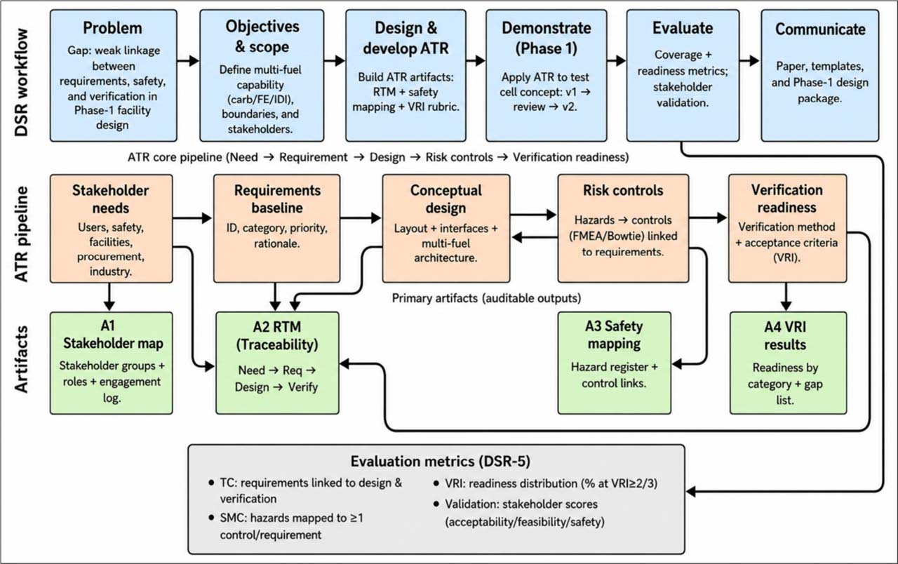
Fig. 1.
Assurance–Traceability–Risk (ATR) conceptual model embedded within the Design Science Research (DSR) workflow for Phase 1 development of a multi-fuel aircraft reciprocating engine test cell.
2.7. Positioning ATR Relative to Established Systems Engineering Approaches
ATR is positioned as a lightweight Phase 1 design-assurance framework, not as a replacement for established systems engineering approaches. Unlike MBSE, which supports formal architecture, interface, behavior, and verification modeling but may require substantial model maturity and resources [43], ATR does not create an executable system model. Instead, it organizes stakeholder needs, requirements, design features, hazard controls, expert comments, and verification evidence into an auditable pre-construction artifact set. ATR also differs from SysML-based traceability because it does not require formal modeling of requirements, system blocks, constraints, interfaces, or verification links within a dedicated modeling environment. Although SysML-based methods strengthen formal traceability, they require modeling tools, expertise, and sufficient design maturity [44]. ATR therefore uses a more accessible RTM-centered structure to establish evidence provenance, design accountability, hazard-control linkage, and verification readiness before detailed engineering begins.
ATR is also related to Digital Thread and Digital Twin approaches but operates at an earlier maturity level. Digital Thread methods connect lifecycle data across design, production, operation, and maintenance [45], while Digital Twins require a physical asset, virtual representation, and continuous physical–digital data exchange [46], [47]. Because the proposed test cell has not yet been fabricated, instrumented, commissioned, or connected to live operational data, ATR functions as a pre-digital-thread evidence structure rather than a Digital Twin. Finally, ATR adapts assurance-case logic by linking claims, evidence, hazards, controls, expert validation, VRI scoring, and Phase 2 action planning [48]. Its contribution is the integration of assurance, traceability, and risk-control evidence into a practical Phase 1 design-governance workflow for a multi-fuel reciprocating engine test cell. A detailed comparison of ATR with MBSE, SysML-based traceability, Digital Thread, Digital Twin, and conventional assurance-case approaches is provided in Appendix Table A1.
3. METHODOLOGY
3.1. Research Design
This study used Design Science Research (DSR) to develop and evaluate a Phase 1 engineering artifact set for a multi-fuel aircraft reciprocating engine test cell. DSR was appropriate because the study aimed not only to describe a test-cell concept, but to produce a usable, evidence-based design-assurance package consisting of an Assurance–Traceability–Risk (ATR) model, requirements baseline, safety mappings, and verification readiness outputs [48]. The artifact was developed for a single conceptual test cell intended to accommodate carbureted, electronic fuel injection (EFI), and direct injection (DI) configurations.
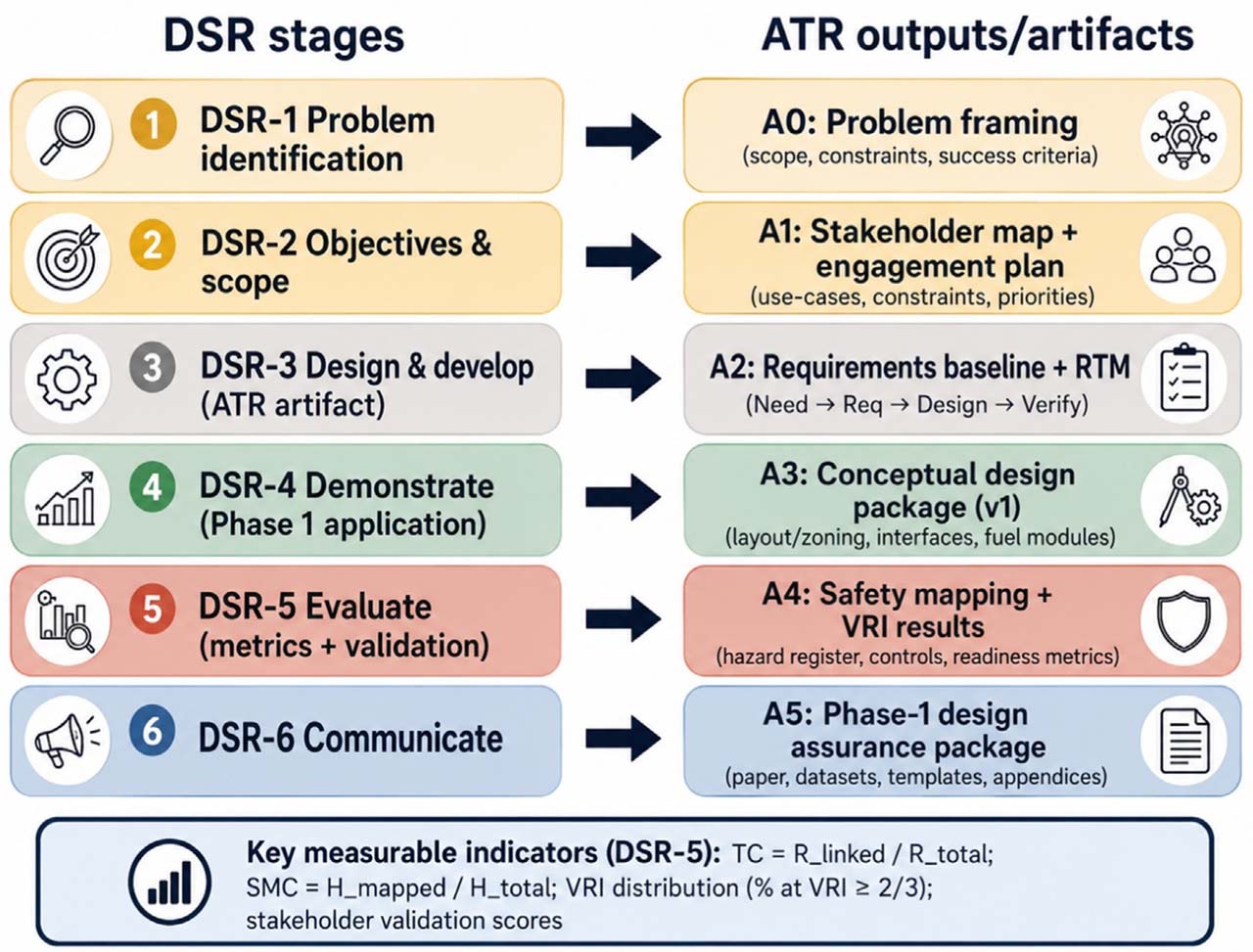
Fig. 2.
Design Science Research (DSR) stages and corresponding Assurance–Traceability–Risk (ATR) outputs/artifacts for Phase 1 of the multi-fuel reciprocating engine test cell project.
Evaluation followed a convergent mixed-methods design. Qualitative evidence from stakeholder interviews, technical expert interviews, expert validation, and design-review deliberations was analyzed alongside quantitative indicators, including traceability coverage, safety mapping coverage, Expert Feasibility Validation (EFV) metrics, and Verification Readiness Index (VRI) scores. The two evidence strands were integrated through joint displays to identify convergence, complementarity, and unresolved discrepancies [49], [50]. As shown in Figure 2, the DSR workflow linked each research stage to a corresponding ATR output: problem identification to problem framing, objective and scope definition to stakeholder mapping, design and development to the requirements baseline and RTM, demonstration to the conceptual design package, evaluation to safety mapping and VRI results, and communication to the Phase 1 design-assurance package. This stage-to-output structure provided an explicit evidence trail from problem framing to artifact communication and supported the study’s replication, auditability, and reviewer transparency [51].
3.2. Study Setting, Scope, and Evaluation Boundary
The study was conducted in an aviation education and applied research context, where the proposed reciprocating engine test cell is intended to support controlled, repeatable, instrumented, and safety-managed engine runs. The system scope covered carbureted, electronic fuel injection (EFI), and direct injection (DI) configurations, with emphasis on fuel routing, control and instrumentation interfaces, safety interlocks, purge/venting provisions, utilities, and configuration-specific hazards. This scope reflects the technical sensitivity of piston-engine fuel and injection systems and treats the test cell as a systems-integration problem at the requirements and conceptual design stage [2], [3].
The study was bounded to Phase 1 pre-construction conceptual design and assurance planning. Phase 1 produced a stakeholder- and expert-reviewed conceptual facility design, requirements baseline, safety mapping, traceability outputs, EFV metrics, VRI scoring, and verification-planning artifacts. It excluded detailed fabrication design, procurement, construction, commissioning, and live engine testing. Therefore, the ATR framework was evaluated as a document-based design-assurance and verification readiness artifact, not as an implemented operational system. Phase 2 will be required to compare planned verification evidence with actual implementation evidence through supplier specifications, engineering calculations, installation records, commissioning tests, and controlled operational runs.
3.3. Participants, Data Sources, and Procedure
Stakeholders were identified through role-based mapping of actors who could influence, validate, implement, operate, or be affected by the Phase 1 outputs. Participants included institutional decision-makers, facilities personnel, faculty, laboratory instructors, student representatives, safety/compliance personnel, and engineering/operations contributors. Technical experts were selected through purposive, criterion-based sampling, supplemented by targeted referrals for expertise in reciprocating engines, carbureted/EFI/DI fuel systems, instrumentation, controls, facilities integration, and test-cell safety. Experts were required to have at least five years of relevant experience, with preference for ten or more years and cross-configuration or interface-integration exposure. This sampling approach supported early requirements development, role diversity, and expert-informed Phase 1 design evidence rather than statistical representativeness [52,53,54]. Information sufficiency was assessed through diminishing new themes across role groups [55]. The final panel comprised 12 individual participants across five role/domain groups: test-cell operations personnel, engine-shop and maintenance personnel, instrumentation/calibration/electrical personnel, quality-control/compliance support, and external industry/training experts. The detailed anonymized profile is provided in Appendix Table A2.
Data were collected using a structured instrument set consisting of stakeholder interview/workshop guides, technical feasibility interview guides, requirements worksheets, rating forms, a design-review checklist, and an expert comment/disposition log. The stakeholder guide captured instructional, operational, safety, infrastructure, and usability requirements, while the expert guide focused on fuel-system interfaces, controls, instrumentation, hazards, maintainability, and implementation constraints for carbureted, EFI, and DI configurations. Semi-structured interviews were used to elicit technical requirements, feasibility concerns, hazards, maintainability issues, and safeguards [56]. The worksheets and checklists standardized requirement capture, prioritization, review, and revision tracking, while the comment/disposition log recorded expert comments, affected artifacts, decision status, rationale, and revision actions [57].
Phase 1 followed an eight-step DSR workflow: (1) stakeholder and context analysis, (2) benchmarking and document review, (3) concept and alternative sketching, (4) requirements enumeration and coding, (5) initial conceptual design development, (6) integrated stakeholder and technical expert review, (7) revision and consolidation of ATR artifacts and conceptual design, and (8) final packaging and communication of Phase 1 outputs. This staged build–evaluate process is consistent with DSR’s emphasis on iterative artifact development and evaluation rather than one-pass descriptive design [48]. Stakeholder and expert review was concentrated in Step 6 to reconcile user needs, operational constraints, and technical feasibility judgments before finalizing the Phase 1 artifact set.
3.4. ATR Model Construction
The ATR model was constructed as an integrated Phase 1 design-governance artifact. Its Assurance component defined the claim-evidence logic used to justify feasibility, safety readiness, and verification readiness. Evidence sources included stakeholder inputs, design-review outputs, technical expert interviews, and disposition records. This claim-evidence structure reflects assurance-case thinking, where design claims must be supported by explicit and reviewable evidence [5]. The Traceability component linked stakeholder needs, derived requirements, conceptual design features, hazard controls, expert comments, and planned verification methods. This was implemented through a coded requirements baseline and RTM-centered linkage structure. The RTM preserved evidence provenance by documenting the source, date/version, analyst notes, linked design feature, hazard/control item, configuration relevance, and verification method. This linkage structure draws on digital-thread and pre-requirements traceability literature concerning connected lifecycle artifacts and early evidence capture [6], [13].
The Risk component captured hazard categories, control mappings, and residual concerns related to fuel-system integration, ignition/fire risk, exhaust and ventilation, mechanical exposure, and human/procedural factors. Hazards were not treated as a standalone list; they were cross-linked to requirements, design provisions, and verification plans. Expert comments were processed through an accept, revise, defer, or reject-with-rationale workflow, then linked to affected RTM entries. This strengthened the auditability of design decisions and aligned with barrier-management thinking, where hazards, controls, and design updates are managed as connected assurance evidence [40]. ATR was implemented as a lightweight Phase 1 assurance framework rather than as a full MBSE, SysML, Digital Thread, or Digital Twin environment. This decision reflected the project’s pre-construction maturity. The framework therefore prioritized evidence provenance, RTM completeness, hazard-control linkage, expert comment disposition, and verification readiness scoring. These outputs prepare the project for later detailed engineering and possible model-based or digital-thread integration, but they do not replace those approaches.
3.5. Operational Definitions and Metrics
This study evaluated Phase 1 outputs using traceability coverage, safety mapping coverage, the Verification Readiness Index (VRI), and Expert Feasibility Validation (EFV). These metrics assessed whether the conceptual test-cell package was complete, traceable, safety-linked, and verification-ready for downstream engineering. The emphasis on evidence links and provenance follows traceability literature on connecting stakeholder inputs, design decisions, requirements, and later engineering artifacts [13], [39]. Traceability coverage was defined as the proportion of approved requirements with complete links to: (a) stakeholder/source origin, (b) mapped design feature, and (c) planned verification method. A requirement was classified as trace-complete only when all three links were present in the RTM and supported by evidence-provenance entries.
Safety mapping coverage was defined as the proportion of identified hazards linked to at least one preventive and/or mitigative control and to the relevant requirement or design element. A hazard was considered mapped only when the control logic and implementation location were documented. This reflects barrier-management logic, where control credibility depends on coordinated and traceable safety barriers rather than isolated hazard lists [58]. The VRI was computed at the requirement level using five attributes: verification method identified, acceptance criterion specified, evidence source defined, verification responsibility assigned, and verification stage/timing indicated. Each attribute was scored as 0 = absent, 1 = partially defined, or 2 = fully defined. The requirement-level VRI was calculated as:
where VRIi is the readiness score for requirement i, Aij is the score for attribute j, and 10 is the maximum raw score. Category-level VRI was calculated as the mean score of all requirements within a category. Readiness bands were defined as High = ≥ 80, Moderate = 60–79, and Low = < 60. Equal weighting was used as the baseline VRI scheme because the five attributes represent minimum necessary conditions for Phase 1 verification readiness. A requirement cannot be considered fully verification-ready if it lacks a method, acceptance criterion, evidence source, responsible party, or verification stage. Equal weighting therefore, preserved transparency and avoided assigning unsupported priority to one attribute before commissioning or operational evidence was available. Alternative schemes, including expert-derived, analytic hierarchy process, and data-driven weighting, were considered but not adopted because the study did not yet include implementation outcomes. For sensitivity analysis, the weighted VRI was computed as: where wj is the assigned weight for attribute j, Σwj = 1, and Aij is the 0–2 attribute score for requirement i.EFV summarized technical expert judgments for carbureted, EFI, and DI compatibility. EFV1 measured feasibility agreement using a five-point scale from 1 = not feasible to 5 = highly feasible. EFV2 summarized inter-expert convergence across fuel routing, instrumentation/control interfaces, safety interlocks, purge/venting, and maintainability. EFV3 counted unresolved high-priority technical issues requiring design revision, engineering calculation, supplier consultation, or Phase 2 verification. EFV4 measured comment disposition closure: EFV4 = (closed expert comments / total expert comments) × 100. A comment was considered closed if accepted, modified, rejected with rationale, or deferred with a defined Phase 2 action. All VRI and EFV scores were linked to the RTM, expert interview summaries, and comment/disposition log to preserve traceability between evidence, design decisions, and reported metrics.
For Phase 2 and commissioning, ATR performance will be evaluated by comparing planned verification evidence with actual implementation evidence. Post-implementation indicators will include requirement verification closure rate, unresolved nonconformity count, safety-control test pass rate, interlock and E-stop test results, fuel-system leak and pressure-test outcomes, ventilation and exhaust performance, instrumentation calibration status, DAQ logging completeness, alarm-threshold performance, configuration-changeover compliance, and controlled engine-run repeatability.
3.6. Data Analysis
Qualitative and quantitative data were analyzed in parallel and integrated during interpretation. Qualitative data from stakeholder and technical expert interviews/workshops were compiled, familiarized, and coded using a structured codebook aligned with ATR domains, while allowing emergent subcodes for unanticipated constraints or hazards. Theme development followed a transparent thematic analysis process involving coding, grouping, review, and refinement [59]. Information sufficiency was assessed through diminishing new codes and themes across role groups [55]. Quantitative analysis used descriptive summaries of traceability coverage, safety mapping coverage, VRI, and EFV metrics. Counts, proportions, means/medians, and dispersion indicators were used as appropriate to compare completeness, feasibility agreement, issue density, and closure status across configurations and subsystems. The quantitative strand was evaluative rather than inferential and was used to identify weakly supported requirements, lower-coverage hazards, and verification gaps requiring revision before finalizing Phase 1 outputs.
A deterministic sensitivity analysis was conducted for the VRI to examine whether the overall readiness interpretation depended on the equal-weighting assumption. The baseline equal-weight model was compared with alternative weighting scenarios emphasizing verification execution, evidence strength, governance responsibility, and verification timing. Overall VRI scores, category-level VRI scores, readiness-band changes, and rank-order changes across requirement categories were compared to determine whether the interpretation remained stable. Mixed-methods integration was conducted through joint displays aligning qualitative themes with quantitative ATR indicators and disposition outcomes. These displays made convergence, complementarity, and discrepancies visible, such as strong feasibility ratings paired with unresolved critical issues. Joint displays were used as both analytic and reporting tools to strengthen transparency in how integrated conclusions were derived [50], [57].
3.7. Trustworthiness and Ethical Considerations
Trustworthiness was strengthened through triangulation, audit trail documentation, and selective member checking. Triangulation compared stakeholder interviews, technical expert interviews, design-review outputs, and ATR metrics to confirm, refine, or challenge emerging interpretations, reducing reliance on a single evidence source and supporting credibility [60]. An audit trail documented codebook revisions, requirement changes, expert comment dispositions, ATR artifact versions, and rationales for accepting, deferring, or rejecting proposed changes. Selective member checking was conducted when feasible by returning summarized interpretations to relevant participants to verify feasibility constraints, requirement clarifications, and safety-control concerns.
Ethical safeguards included informed consent, voluntary participation, optional artifact review, and the right to withdraw without penalty. No sensitive personal data were intentionally collected. Participants were anonymized by role category, and participating organizations were identified only by site labels and organization type. Recordings, transcripts, RTM/ATR files, and comment/disposition logs were stored in password-protected files with access limited to the research team. Because the study was limited to pre-construction conceptual design and did not involve live engine testing, instructional intervention, student assessment, or student academic data, it was treated as minimal risk.
4. RESULTS
4.1. Participant Profile and Evidence Sources
The Phase 1 evidence base was drawn from 12 individual participants across test-cell operations, aircraft maintenance, engine-shop supervision, instrumentation/calibration, electrical/avionics support, quality/compliance, and aviation training perspectives. To preserve confidentiality, participants were grouped under three anonymized organization types: Site A, a military aircraft maintenance organization; Site B, a general aviation maintenance/service provider; and Site C, an aviation training provider. The detailed anonymized participant profile, organized by primary role/domain and corresponding site/source context, is provided in Appendix Table A2.
These sources generated evidence on existing carbureted/EFI capability, DI feasibility limitations, modular fuel-routing needs, instrumentation and DAQ requirements, ventilation and exhaust constraints, safety interlocks, documentation controls, and pre-construction verification requirements. The panel provided cross-role technical coverage for Phase 1 design assurance, particularly in multi-fuel compatibility, instrumentation readiness, safety-control mapping, and verification planning. However, it was not intended to represent all aviation maintenance organizations, MROs, engine test-cell operators, or aviation training institutions. The findings therefore support analytic transferability to similar aviation education or applied research facilities, but not statistical generalization.
4.2. Stakeholder-Driven Requirements Baseline
The stakeholder-driven requirements baseline addressed RQ1 by translating interview, workshop, and benchmarking evidence into Phase 1 requirements for the proposed multi-fuel reciprocating engine test cell. As shown in Table 1 and Figure 3, 42 requirements were identified across seven categories, with the largest clusters in instrumentation/DAQ and calibration, fuel architecture, controls/interlocks, and ventilation/exhaust/noise control. The results indicate that stakeholders viewed the test cell as a safety-managed, configurable, and instrumented training/research system rather than a simple engine-run enclosure.
Table 1.
Stakeholder-Driven Requirements Baseline by Category, Priority, and Source.
| Requirement category | No. of requirements | Main priority level | Main contributing source groups | Typical requirement focus |
|---|---|---|---|---|
| Multi-configuration fuel architecture | 7 | P1–P2 | Test-cell operators; engine-shop personnel; external training/industry experts | Carb/EFI/DI compatibility, modular/separate fuel routing, supply/return lines, filters, regulators, selectors, shutoff, compartmentalized fuel systems |
| Controls/interlocks and operational safety | 7 | P1 | Test-cell operators; engine-shop personnel; external experts | E-stop, fuel shutoff, master switch, fire response, safety barriers, signage, configuration safety controls |
| Instrumentation/DAQ and calibration | 8 | P1–P2 | Instrumentation/calibration personnel; electrical/avionics personnel; external experts | RPM, oil pressure/temperature, CHT, EGT, fuel pressure/flow, MAP, analog/digital display, logging, calibration control |
| Facility ventilation/exhaust/noise control | 7 | P1–P2 | Test-cell operators; external experts; safety/compliance contributors | Fresh-air supply, exhaust routing, negative pressure, CO/fire considerations, heat protection, muffler/silencer, noise control |
| Structural/layout and utilities | 5 | P1–P2 | Engine-shop personnel; test-cell operators; electrical support | Engine geometry, structural loads, engine mounting, high ceiling, propeller guard, grounding, electrical readiness |
| Operations/human factors and maintenance procedures | 5 | P2–P3 | Operators; maintenance personnel; quality/compliance contributors | Checklists, routine inspection, pre-start procedures, standard run-in profile, cable/harness marking, coordination protocols |
| Verification/compliance readiness | 3 | P1 | Test-cell operators; external experts; quality/compliance contributors | Frozen requirements, final drawings/calculations, safety/compliance review, design-ready acceptance criteria |
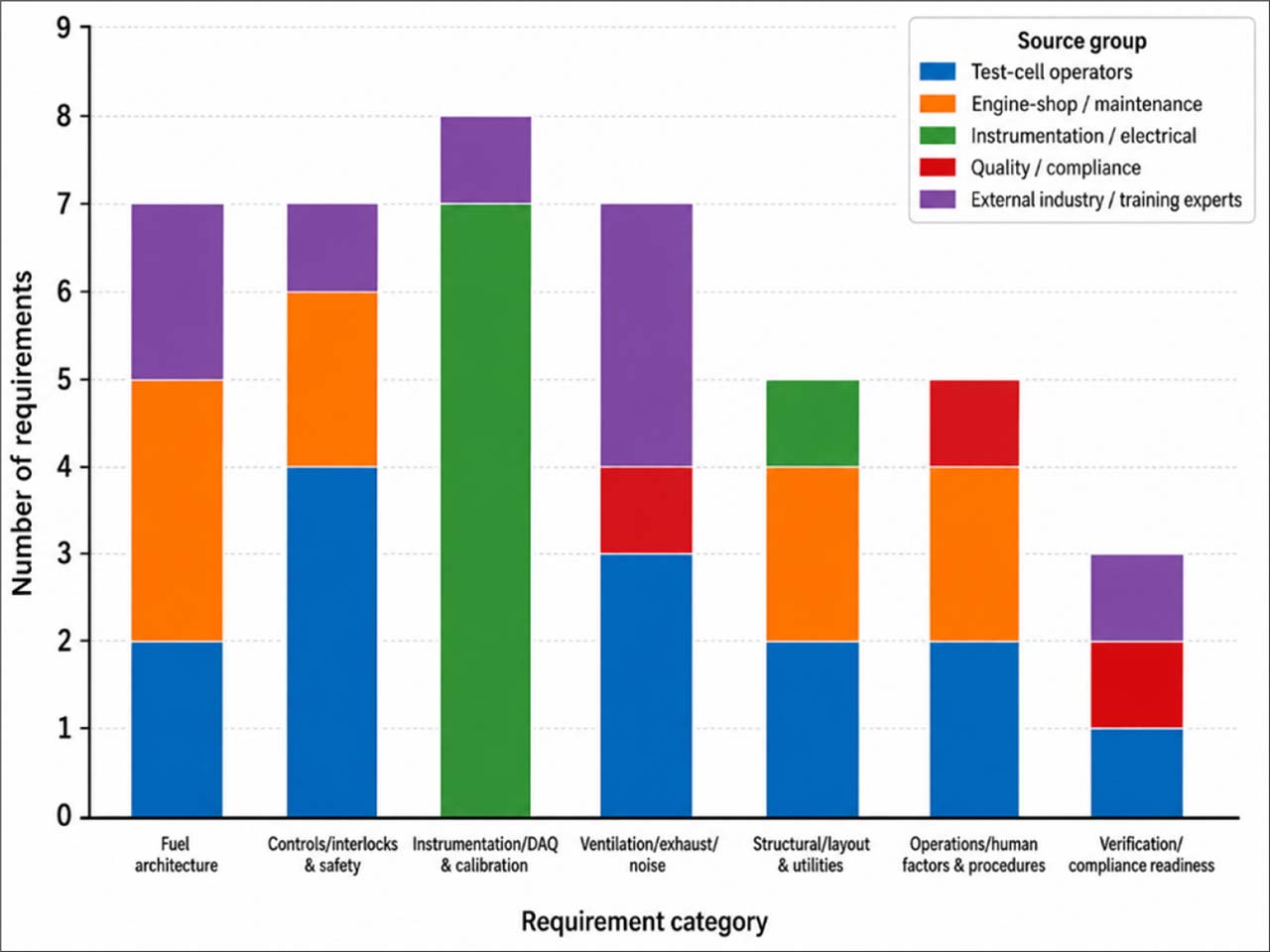
Fig. 3.
Distribution of stakeholder-derived requirements by category and source group.
4.3. Conceptual Design Outputs for Multi-Fuel Compatibility
The conceptual design outputs addressed the design-feature component of RQ2 by showing how carbureted, EFI, and DI compatibility were translated into modular layout, fuel-routing, instrumentation, safety, purge/venting, utility, and zoning provisions. As summarized in Table 2 and Figure 4, carbureted and EFI provisions were more fully specified, while DI was retained as a reserved future-compatible capability through high-pressure routing provisions, configuration-specific fittings, enhanced inspection points, pressure safeguards, and additional safety barriers. This confirms that the Phase 1 design supports carbureted and EFI readiness more strongly, whereas DI remains dependent on Phase 2 technical verification.
Table 2.
Conceptual Design Outputs for Multi-Fuel Compatibility.
| Design area | Carbureted configuration | EFI configuration | DI configuration | Conceptual design output |
|---|---|---|---|---|
| Fuel routing | Gravity/feed line, pump, filter, selector, shutoff | Pump, filter, supply/return line, pressure regulation, shutoff | Reserved high-pressure routing provision, fittings, barriers, inspection points | Modular/compartmentalized fuel-routing panel with separated paths per configuration |
| Instrumentation/DAQ | RPM, oil pressure/temp, CHT, EGT, MAP | RPM, oil pressure/temp, CHT, EGT, MAP, fuel pressure/flow | Expanded fuel pressure/flow monitoring and configuration-specific DAQ points | Hybrid analog–digital instrumentation with calibration-ready DAQ and logging |
| Safety interlocks | E-stop, fuel shutoff, master switch, fire response | E-stop, fuel shutoff, electrical isolation, checklist control | E-stop, fuel shutoff, pressure-related safeguards, enhanced inspection control | Common safety-interlock layer with configuration specific permissives |
| Purge/venting | Ventilation for fumes, heat, and exhaust | Ventilation for fuel vapor, heat, and exhaust | Enhanced purge/venting provision before DI adoption | Dedicated ventilation/exhaust system with negative-pressure and backpressure considerations |
| Utilities | Engine mounting, basic electrical supply, grounding | Electrical/DAQ support, grounding, sensor wiring | Reserved utility capacity for advanced controls and higher monitoring demand | Utility-ready layout for power, grounding, DAQ, cooling, ventilation, and maintenance access |
| Layout logic | Engine bay + fuel panel + operator control | Engine bay + fuel/control panel + DAQ interface | Engine bay with reserved DI-safe routing and control provisions | Separated zones for engine bay, modular fuel/control panels, DAQ/control room, exhaust path, and safety access |
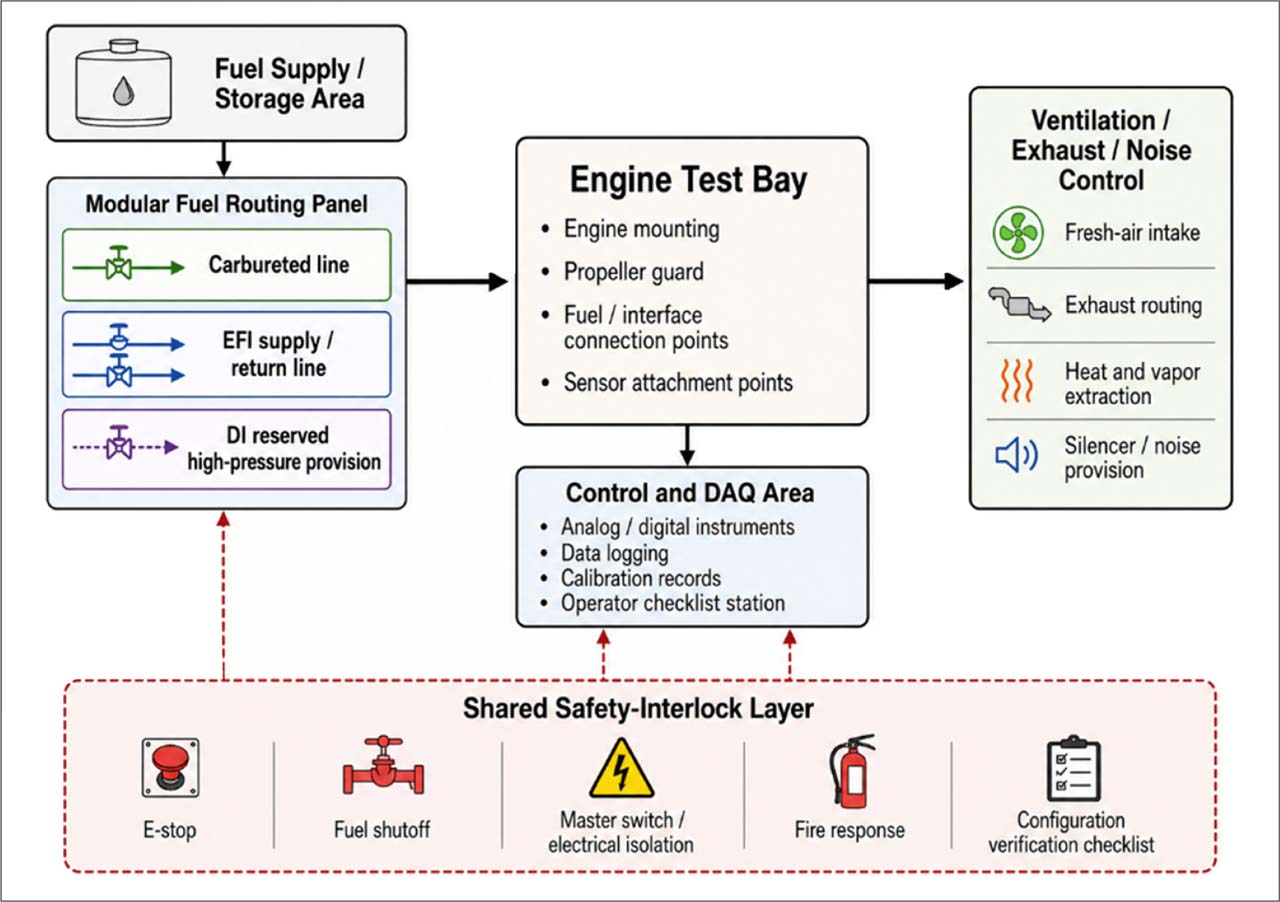
Fig. 4.
Conceptual layout logic for multi-fuel compatibility showing separated fuel-routing paths, engine test bay, DAQ/control area, ventilation/exhaust system, and shared safety-interlock layer.
4.4. Traceability Coverage Results
The RTM coverage analysis further addressed RQ2 by assessing whether the 42 requirements were linked to source evidence, design features, and planned verification methods. As shown in Table 3 and Figure 5, all requirements were source-linked, 39 requirements were design-feature-linked, 35 were verification-method-linked, and 34 were trace-complete, producing an overall trace-complete rate of 81.0%. The main traceability gaps involved operations/procedures, verification/compliance readiness, and DI-related verification pathways that still require Phase 2 definition.
Table 3.
RTM Traceability Coverage by Requirement Category.
| Requirement category | Total requirements | With source link | With design-feature link | With verification-method link | Trace-complete requirements | Trace-complete (%) |
|---|---|---|---|---|---|---|
| Multi-configuration fuel architecture | 7 | 7 | 7 | 6 | 6 | 85.70 |
| Controls/interlocks and operational safety | 7 | 7 | 7 | 7 | 7 | 100.00 |
| Instrumentation/DAQ and calibration | 8 | 8 | 8 | 7 | 7 | 87.50 |
| Facility ventilation/exhaust/noise control | 7 | 7 | 6 | 6 | 6 | 85.70 |
| Structural/layout and utilities | 5 | 5 | 5 | 4 | 4 | 80.00 |
| Operations/human factors and maintenance procedures | 5 | 5 | 4 | 3 | 3 | 60.00 |
| Verification/compliance readiness | 3 | 3 | 2 | 2 | 1 | 33.30 |
| Total | 42 | 42 | 39 | 35 | 34 | 81.00 |
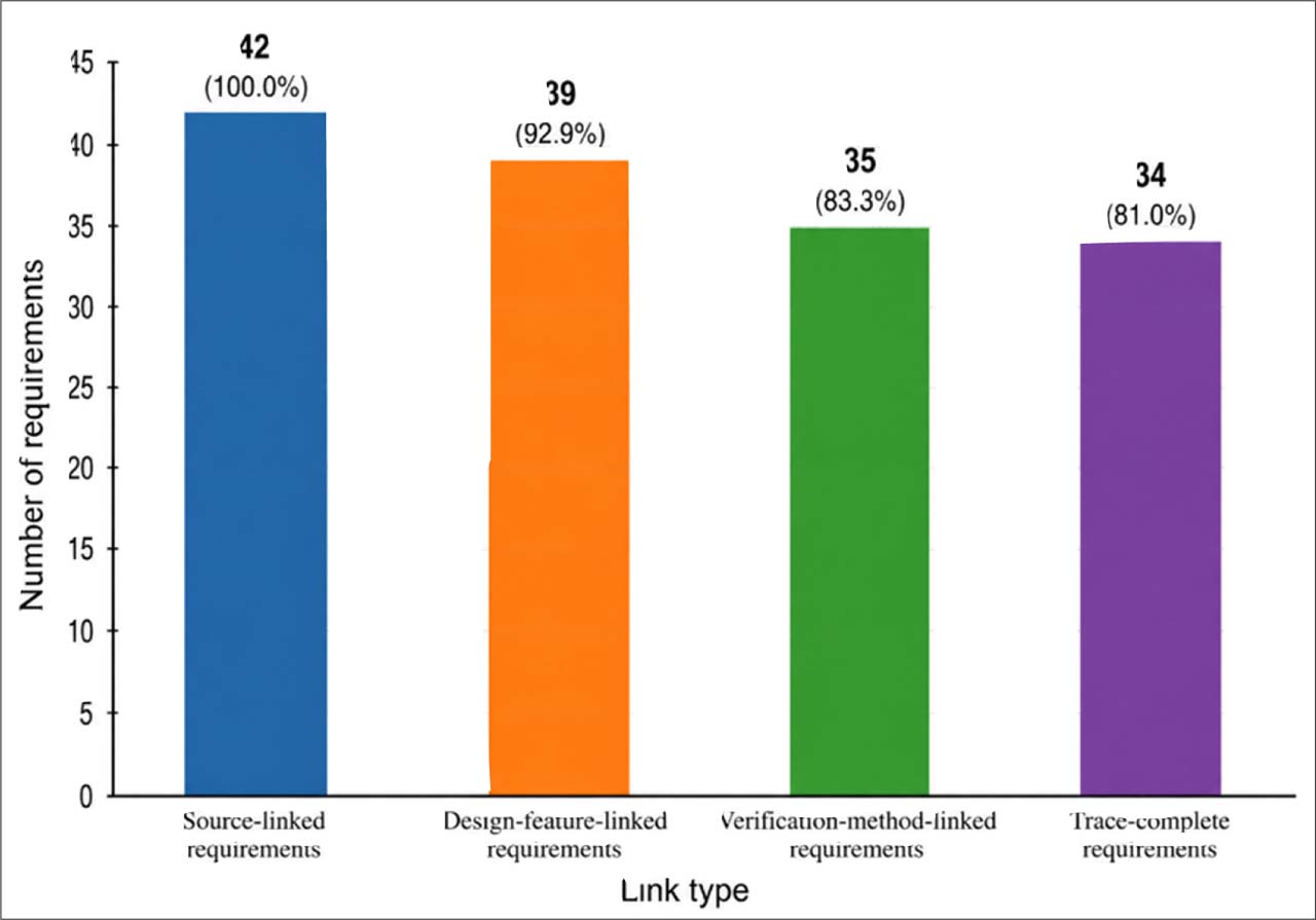
Fig. 5.
RTM Coverage by Link Type.
4.5. Safety Mapping Results
The safety mapping results addressed RQ3 by identifying dominant hazard scenarios and linking them to preventive controls, mitigative controls, design features, and verification actions. As summarized in Table 4 and Figure 6, 18 hazard scenarios were identified, 16 hazards were mapped to at least one control, and 14 had both preventive and mitigative controls, corresponding to 88.9% mapping coverage and 77.8% dual-control coverage. Remaining priority gaps involved DI high-pressure provisions, ventilation/exhaust criteria, CO/fire monitoring assumptions, DAQ alarm/logging functions, and formal verification of heat, noise, and exhaust-control performance.
Table 4.
Hazard-Control Mapping Summary.
| Hazard category | No. of hazard scenarios | Main hazards identified | Preventive controls mapped | Mitigative controls mapped | Coverage status | High-priority gaps |
|---|---|---|---|---|---|---|
| Fuel handling and configuration changeover | 4 | Leakage, contamination, incorrect configuration, fuel-routing mismatch | Modular/separated routing, fuel selector, filters, pressure regulator, shutoff valve, configuration checklist | Immediate repair/maintenance response, routine inspection, isolation of affected line | Strong | DI high-pressure routing, fittings, barriers, and inspection protocol require further verification |
| Electrical/control-system faults | 3 | Short circuit, control malfunction, unsafe start/run condition | Master switch, electrical isolation, harness marking, checklist verification | E-stop, fuel shutoff, emergency response | Strong | Detailed E-stop logic and interlock verification still needed |
| Instrumentation, DAQ, and calibration | 3 | Inaccurate readings, limited sensor coverage, poor data traceability | Calibration schedule, in-date instrument checks, minimum sensor suite, analog/digital display | Reasonableness checks, maintenance of instruments, data review | Moderate to strong | Alarm thresholds, DAQ logging, and traceable digital records require refinement |
| Ventilation, exhaust, heat, and noise | 4 | Fuel vapor accumulation, poor exhaust routing, heat exposure, excessive noise | High-capacity ventilation, fresh-air intake, exhaust routing, silencer/noise provision, CO/fire consideration | Fire guard, heat/vapor extraction, community/safety consultation | Moderate | Negative pressure, backpressure limits, CO monitoring, and noise-control design need formal calculation |
| Mechanical/structural hazards | 2 | Engine mounting failure, propeller exposure, vibration/structural load risk | Engine geometry checks, structural load review, propeller guard, high-ceiling provision | Physical guarding, controlled test bay access | Moderate to strong | Structural calculations and propeller-guard dimensions require Phase 2 confirmation |
| Human-factor/procedural risks | 2 | Checklist omission, poor contractor–proponent coordination, setup error | Pre-start checklist, standard run-in procedure, stakeholder coordination, configuration marking | Review/correction through disposition log and design review | Moderate | Formal configuration-control procedure and responsibility matrix needed |
| Total | 18 | — | 16 hazards with preventive/mitigative control linkage | 14 hazards with both preventive and mitigative controls | 88.9% mapped; 77.8% dual-control coverage | DI, ventilation/exhaust, DAQ alarms, and verification criteria remain priority gaps |
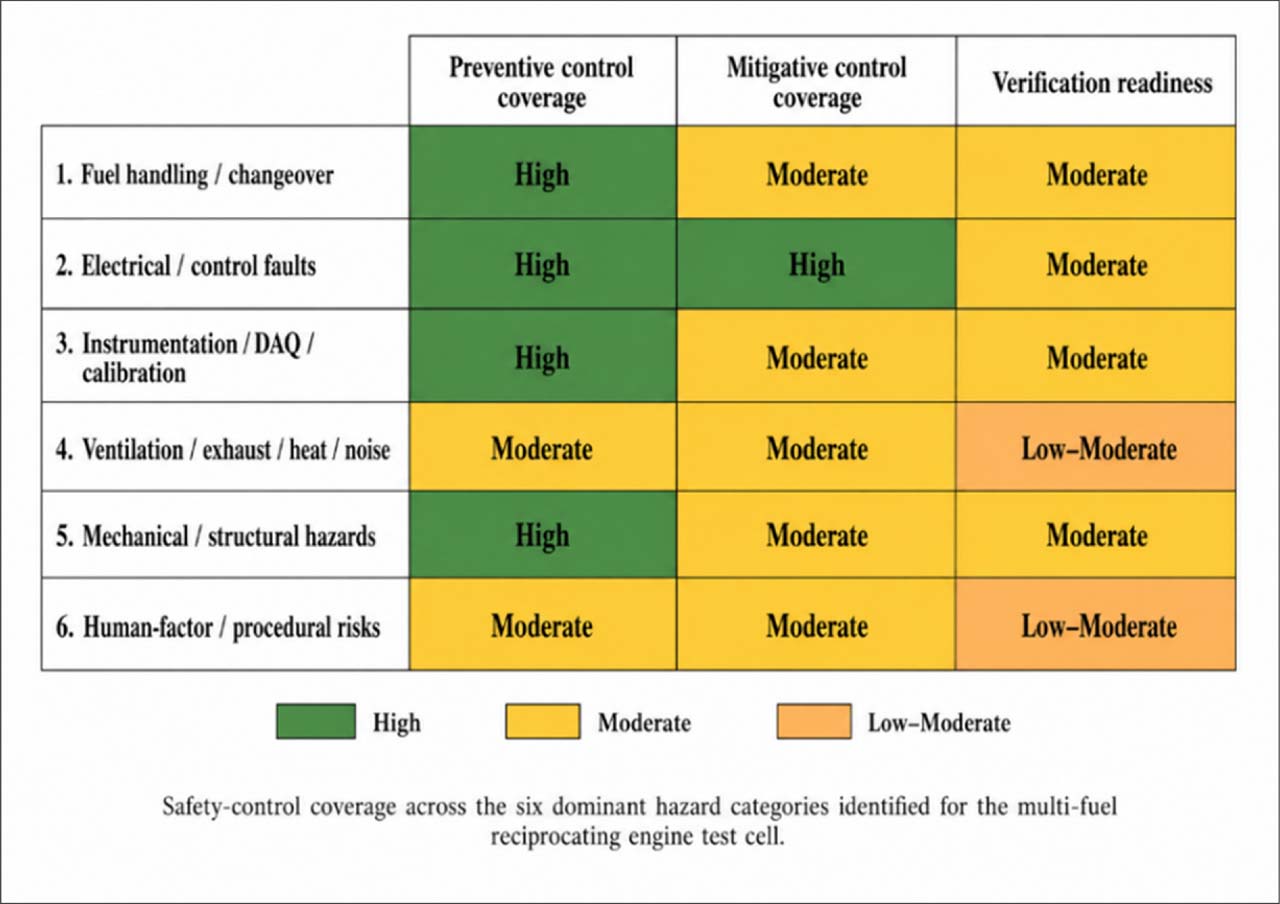
Fig. 6.
Safety-control coverage heat map.
4.6. Verification Readiness Index Results
The VRI addressed RQ4 by assessing how prepared the Phase 1 requirements were for downstream verification planning. As shown in Table 5 and Figure 7, the overall VRI was 78.2/100, indicating moderate-to-high verification readiness; 21 requirements reached the high-readiness band, 17 were moderate, and 4 remained low. The strongest readiness scores were observed in controls/interlocks and operational safety, instrumentation/DAQ and calibration, and multi-configuration fuel architecture, while lower readiness was concentrated in ventilation/exhaust/noise control, operations/procedures, verification/compliance readiness, and DI-specific provisions.
The sensitivity analysis confirmed that the VRI interpretation was stable under alternative weighting assumptions. As shown in Table 6, the baseline equal-weight model reproduced the reported overall VRI of 78.2/100, while the alternative weighting scenarios ranged from 77.6 to 80.2. This indicates that the moderate-to-high readiness conclusion was not materially dependent on the equal-weighting assumption.
Table 5.
Verification Readiness Index Results by Requirement Category.
| Requirement category | Total requirements | High readiness | Moderate readiness | Low readiness | Mean VRI score | Readiness interpretation |
|---|---|---|---|---|---|---|
| Multi-configuration fuel architecture | 7 | 5 | 2 | 0 | 82.9 | High |
| Controls/interlocks and operational safety | 7 | 6 | 1 | 0 | 90.0 | High |
| Instrumentation/DAQ and calibration | 8 | 5 | 3 | 0 | 83.8 | High |
| Facility ventilation/exhaust/noise control | 7 | 2 | 4 | 1 | 72.9 | Moderate |
| Structural/layout and utilities | 5 | 2 | 2 | 1 | 76.0 | Moderate |
| Operations/human factors and maintenance procedures | 5 | 1 | 3 | 1 | 66.0 | Moderate |
| Verification/compliance readiness | 3 | 0 | 2 | 1 | 61.7 | Moderate–low |
| Total / Overall | 42 | 21 | 17 | 4 | 78.2 | Moderate–high |
The remaining readiness gaps define the Phase 2 validation agenda rather than evidence of completed implementation. As summarized in Table 7, the main gaps involve DI-specific fuel-system provisions, ventilation and exhaust performance, noise and heat control, E-stop/interlock logic, DAQ alarms and digital logging, structural and propeller-guard confirmation, and configuration-control procedures. Appendix Table A3 further specifies the post-implementation metrics needed to validate ATR during detailed engineering, commissioning, and controlled operation, including requirement verification closure, nonconformity resolution, safety-control test pass rate, leak/pressure-test outcomes, ventilation/exhaust performance, DAQ logging completeness, alarm-threshold performance, configuration-changeover compliance, and controlled engine-run repeatability. Therefore, the VRI results should be interpreted as a Phase 1 verification-planning baseline, not as proof of build readiness, commissioning success, or operational effectiveness.
Table 6.
VRI Sensitivity Analysis Under Alternative Weighting Scenarios.
| Scenario | Verification method | Acceptance criterion | Evidence source | Responsibility | Stage/timing | Overall VRI | Readiness band | Interpretation |
|---|---|---|---|---|---|---|---|---|
| Baseline equal weights | 0.2 | 0.2 | 0.2 | 0.2 | 0.2 | 78.2 | Moderate–high | Primary reported equal-weight VRI |
| Verification-execution emphasis | 0.3 | 0.3 | 0.15 | 0.15 | 0.1 | 77.6 | Moderate–high | Tests emphasis on verification method and acceptance criteria |
| Evidence-assurance emphasis | 0.15 | 0.15 | 0.3 | 0.2 | 0.2 | 80.2 | High | Tests emphasis on evidence source and assurance support |
| Governance emphasis | 0.15 | 0.15 | 0.2 | 0.25 | 0.25 | 77.7 | Moderate–high | Tests emphasis on responsibility and verification timing maturity |
| Method-and-criteria reduced | 0.15 | 0.15 | 0.25 | 0.25 | 0.2 | 78.8 | Moderate–high | Tests reduced dependence on method and criteria |
[i] Note. The baseline equal-weight scenario uses the same requirement-level VRI calculation reported in Table 5; therefore, both tables report the same overall VRI of 78.2/100. Alternative scenarios apply different attribute weights for sensitivity analysis.
Table 7.
Verification Readiness Gaps and Phase 2 Action Priorities.
| Readiness gap | Affected requirement area | Reason for lower readiness | Required Phase 2 action |
|---|---|---|---|
| DI-specific fuel-system provisions | Multi-configuration fuel architecture | Limited direct DI test-cell experience among experts; high-pressure routing and fittings not yet technically specified | Conduct supplier/technical consultation, pressure-rating review, and DI-specific safety validation |
| Ventilation/exhaust performance | Facility ventilation/exhaust/noise control | Ventilation need was strongly identified, but airflow, negative pressure, heat load, and backpressure values remain uncalculated | Perform ventilation/exhaust engineering calculations and define acceptance criteria |
| Noise and heat control | Facility ventilation/exhaust/noise control | Noise and heat concerns were identified, but control performance remains conceptual | Specify silencer/muffler, heat shielding, and noise-control performance targets |
| E-stop and interlock logic | Controls/interlocks and operational safety | Safety functions were identified as critical, but logic sequence and response criteria remain preliminary | Develop interlock logic diagram and verification test procedure |
| DAQ alarms and digital logging | Instrumentation/DAQ and calibration | Sensor suite was identified, but alarm thresholds, sampling/logging, and traceability rules need refinement | Define DAQ specification, calibration traceability, alarm thresholds, and data-recording protocol |
| Structural and propeller-guard confirmation | Structural/layout and utilities | Mounting, high ceiling, and propeller guard were identified, but dimensions and load calculations remain pending | Complete structural/load review and guard-spacing verification |
| Configuration-control procedure | Operations/human factors and maintenance procedures | Checklist use was emphasized, but formal responsibility and configuration-change workflow remain incomplete | Develop configuration-control checklist, responsibility matrix, and changeover verification form |
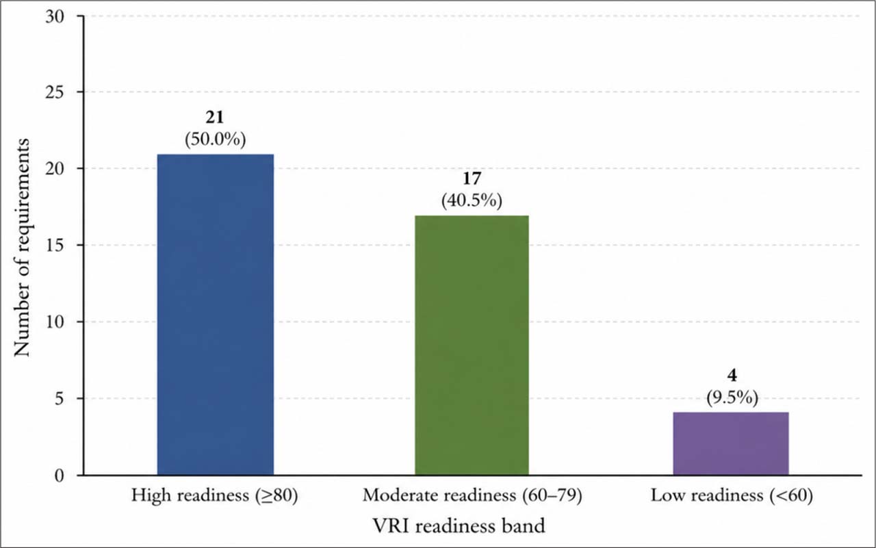
Fig. 7.
VRI Score Distribution by Readiness Band.
4.7. Technical Expert Feasibility Validation Results
The EFV results addressed RQ5 by assessing the technical feasibility of carbureted, EFI, and DI compatibility for the proposed multi-fuel reciprocating engine test cell. As shown in Table 8 and Figure 8, carbureted and EFI configurations received stronger feasibility support, with mean EFV1 ratings of 4.5/5.0 and 4.3/5.0, respectively, while DI received a lower rating of 2.8/5.0 and remained conditionally feasible. Expert convergence was high for carbureted and EFI configurations because their fuel-routing, instrumentation, safety, and operational requirements were familiar to the consulted sites. In contrast, DI showed low-to-moderate convergence, the highest critical issue density, and the lowest comment-closure result. EFV4 closure was 7 of 7 comments closed for carbureted provisions (100%), 6 of 7 comments closed for EFI provisions (86%), and 4 of 7 comments closed for DI provisions (57%), indicating that DI retained more unresolved items requiring Phase 2 technical validation.
The unresolved DI concerns involved high-pressure fuel routing, fittings, safety barriers, inspection requirements, control logic, DAQ monitoring, ventilation/exhaust assumptions, and configuration-control procedures. Overall, Table 8 indicates that carbureted and EFI provisions are ready for detailed design, whereas DI should remain a reserved future-compatible capability. Figure 8 visually reinforces this pattern by showing stronger feasibility for carbureted and EFI configurations and a lower technical-readiness profile for DI, confirming that DI requires further Phase 2 technical validation before it can be treated as an operationally ready configuration.
Table 8.
Technical Expert Feasibility Validation Results by Configuration.
| EFV metric | Carbureted | EFI | DI | Interpretation |
|---|---|---|---|---|
| EFV1. Feasibility rating | 4.5 / 5.0 | 4.3 / 5.0 | 2.8 / 5.0 | Carbureted and EFI are highly feasible; DI is conditionally feasible |
| EFV2. Inter-expert convergence | High | High | Low–moderate | Agreement was strongest for existing carb/EFI capability and weaker for DI |
| EFV3. Critical issue density | Low | Moderate | High | DI generated the most unresolved technical concerns |
| EFV4. Comment closure | 7/7 comments closed 100%) | 6/7 comments closed (86%) | 4/7 comments closed (57%) | Carbureted and EFI comments were mostly resolved; DI retained more unresolved issues requiring Phase 2 verification |
| Overall readiness judgment | Ready for detailed design | Ready for detailed design | Requires further technical validation | DI should remain a reserved/future-compatible provision |
[i] Note. EFV1 values are mean expert feasibility ratings based on a five-point scale: 1 = not feasible; 2 = weak feasibility; 3 = conditionally feasible; 4 = feasible; 5 = highly feasible. EFV4 reports the number of expert comments closed out of the total expert comments recorded for each configuration; percentages are rounded to whole numbers because the denominator is small.
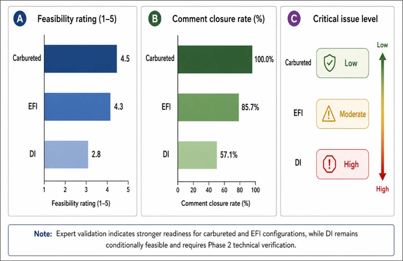
Fig. 8.
Technical Expert Feasibility Profile by Configuration.
4.8. Integrated Joint Display of ATR Findings
The integrated joint display synthesized findings across RQ1–RQ5 by combining qualitative themes from stakeholder and technical expert interviews with quantitative ATR indicators from the requirements baseline, conceptual design outputs, RTM coverage, safety mapping, VRI results, and EFV ratings. As shown in Figure 9, the strongest convergence was observed for carbureted/EFI compatibility, safety interlocks, instrumentation/DAQ, calibration readiness, and traceability completeness. These areas showed consistent alignment across participant evidence, design outputs, traceability coverage, safety-control mapping, verification readiness, and expert feasibility ratings.
Partial or complementary convergence was observed for DI provisions, ventilation/exhaust performance, human factors, and configuration-control procedures. In these areas, stakeholder and expert concerns were clearly identified, but readiness remained lower because some verification methods, acceptance criteria, engineering calculations, supplier specifications, and Phase 2 validation evidence were still pending. The detailed evidence integration, including qualitative themes, supporting indicators, integration results, and Phase 2 implications, is provided in Appendix Table A4. Overall, the integrated findings indicate that ATR provides a coherent Phase 1 evidence structure for conceptual feasibility and verification readiness. However, Figure 9 also highlights that the framework identifies unresolved technical priorities that must be addressed before fabrication, commissioning, controlled engine runs, or operational validation.
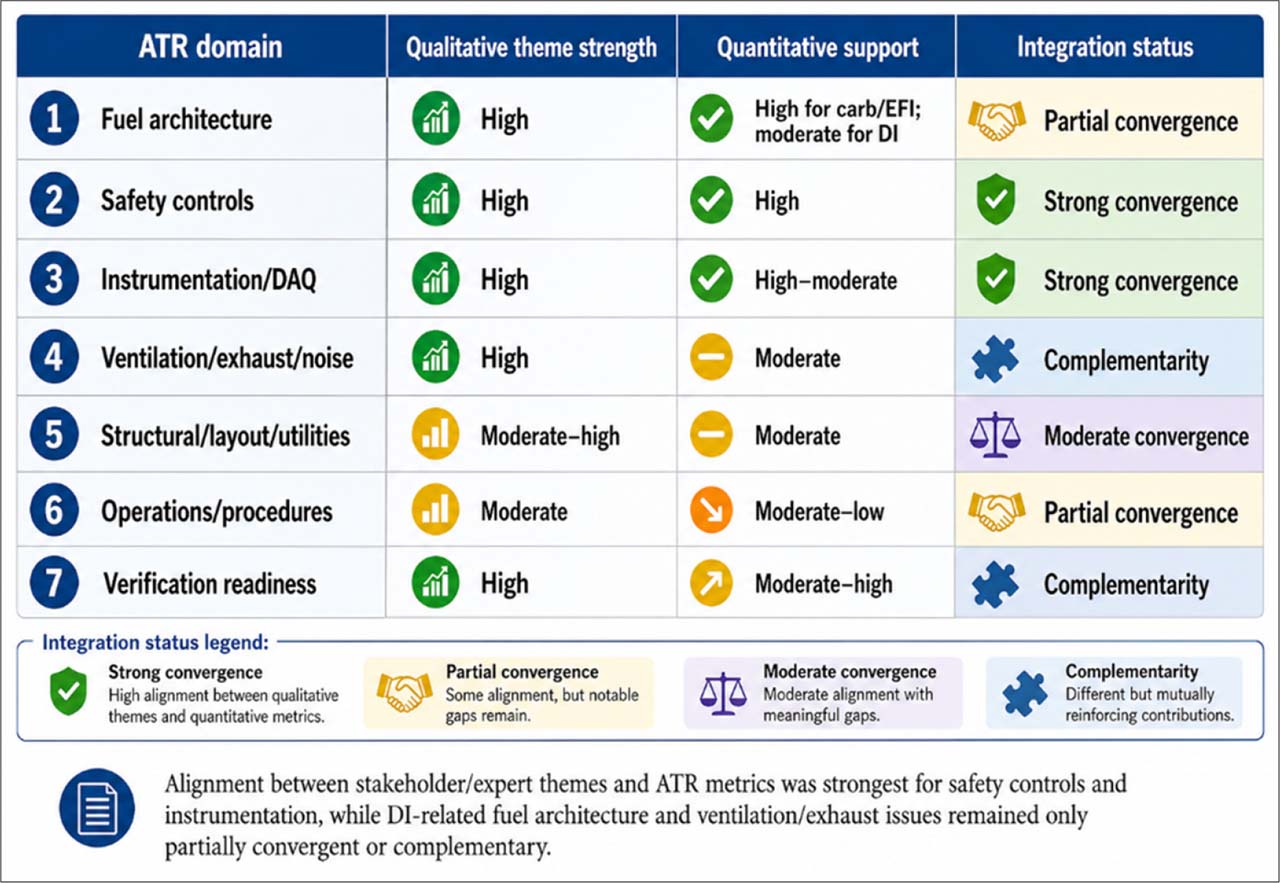
Fig. 9.
Integrated ATR Convergence Matrix.
5. DISCUSSION
5.1. Integrated interpretation of ATR findings
The findings show that Phase 1 development of a multi-fuel reciprocating engine test cell is not merely a facility-layout task but a systems-integration problem involving fuel architecture, instrumentation, safety controls, human procedures, and verification planning. The requirements baseline produced 42 stakeholder-derived requirements across seven categories, with the strongest clusters in fuel architecture, controls/interlocks, instrumentation/DAQ, and ventilation/exhaust/noise control. This indicates that stakeholders viewed the test cell as a controlled training and research infrastructure requiring configuration changeover, repeatability, calibration, and operational safety from the earliest design stage. Carbureted and EFI compatibility were supported more strongly by existing expertise and clearer design provisions, while DI remained a future-compatible capability requiring further technical validation.
ATR strengthened Phase 1 design assurance by linking requirements to source evidence, design features, hazard controls, and verification methods. The RTM showed that all 42 requirements were source-linked, 39 were linked to design features, 35 had verification-method links, and 34 were trace-complete, yielding an overall trace-complete rate of 81.0%. These results indicate that the study moved beyond descriptive concept design by producing an auditable design-assurance package. The strongest traceability appeared in fuel architecture, controls/interlocks, and instrumentation/DAQ, while weaker coverage in operations/procedures and verification/compliance readiness indicates the need for clearer ownership, acceptance criteria, and Phase 2 verification pathways.
The safety mapping results further show the value of treating hazards and controls as connected assurance evidence rather than isolated checklist items. Of the 18 hazard scenarios identified, 16 were linked to at least one preventive or mitigative control, and 14 had both preventive and mitigative controls. Stronger mapping was evident for fuel-system changeover and controls/interlocks, including E-stop logic, fuel shutoff, electrical isolation, fire response, routine inspection, and checklist use. Remaining safety gaps—DI high-pressure provisions, ventilation/exhaust calculations, CO/fire monitoring assumptions, DAQ alarm thresholds, and noise/heat-control performance—clarify the boundary between conceptual assurance and operational validation.
The VRI results indicate that the Phase 1 artifact package achieved moderate-to-high verification readiness, with an overall score of 78.2/100. Of the 42 requirements, 21 reached high readiness, 17 were moderate, and 4 remained low. Sensitivity analysis showed that the overall VRI remained stable under alternative weighting scenarios, ranging from 77.6 to 80.2, suggesting that the readiness interpretation was not dependent on the equal-weighting assumption. Overall, ATR’s integrated contribution lies in converting stakeholder needs, expert judgments, traceability evidence, hazard-control mapping, and verification readiness scoring into a coherent Phase 1 governance workflow. The framework supports defensible progression to detailed engineering, but its results should be interpreted as conceptual feasibility and verification readiness—not as evidence of fabrication readiness, commissioning success, or operational effectiveness.
5.2. DI compatibility and Phase 2 technical priorities
The technical expert validation results qualify the study’s multi-fuel compatibility claim. Carbureted and EFI configurations received stronger feasibility support, with mean ratings of 4.5/5.0 and 4.3/5.0, respectively, and higher comment closure: 7 of 7 comments closed for carbureted provisions (100%) and 6 of 7 comments closed for EFI provisions (86%). In contrast, DI received a lower feasibility rating of 2.8/5.0 and lower comment closure, with 4 of 7 comments closed (57%), reflecting unresolved concerns involving high-pressure fuel routing, fittings, safety barriers, inspection points, control logic, DAQ monitoring, ventilation/exhaust assumptions, and configuration-control procedures. Therefore, DI compatibility should be interpreted as conceptual accommodation and reserved future capability, not as operational readiness.
Although the Phase 1 concept includes DI provisions such as reserved high-pressure routing, configuration-specific fittings, pressure-related safeguards, expanded pressure/flow monitoring, and enhanced inspection points, these remain design assumptions requiring Phase 2 verification. Before DI can advance to detailed design or commissioning, supplier-confirmed specifications are needed for high-pressure pumps, rails, lines, fittings, regulators, relief devices, isolation points, pressure ratings, material compatibility, leak-test criteria, and safe depressurization procedures. DI-specific control logic must also define start permissives, pressure monitoring, emergency shutdown, fuel isolation, electrical isolation, and fault-response behavior.
Phase 2 should further validate DI-related instrumentation, DAQ, ventilation, exhaust, heat, fire/CO monitoring, and configuration-control requirements. This includes suitable pressure transducers, sampling rates, alarm thresholds, calibration traceability, data logging, abnormal-pressure detection, airflow and backpressure calculations, vapor extraction, heat-control provisions, and controlled changeover procedures. Configuration change from carbureted or EFI operation to DI-reserved operation should be governed by checklists, responsibility assignments, line-isolation checks, fitting verification, inspection hold points, and configuration-status documentation. Thus, ATR’s practical value is not that it proves DI effectiveness, but that it identifies the evidence needed to convert DI from conceptual accommodation into verified operating capability through supplier review, pressure-system validation, interlock testing, DAQ alarm validation, ventilation/exhaust verification, and controlled engine-run trials.
5.3. Positioning, novelty, and practical implications
The novelty of ATR lies in its integrated and context-specific use as a lightweight Phase 1 design-assurance workflow, not in replacing established systems engineering approaches. MBSE, SysML-based traceability, Digital Thread/Digital Twin methods, and assurance-case frameworks already provide mature principles for model consistency, traceability, lifecycle evidence management, and safety argumentation [42,43,44,45]; [47]. However, these approaches often require modeling maturity, software environments, operational data, or detailed system definitions that may not yet exist during early facility development. ATR addresses this gap by translating selected principles from these methods into a practical pre-construction artifact set linking stakeholder requirements, expert feasibility judgments, design features, hazard controls, and verification readiness evidence. It should therefore be understood as a bridge between informal conceptual design and later formal MBSE, SysML, Digital Thread, Digital Twin, or assurance-case implementation, rather than as a substitute for those approaches.
For aviation education and applied research facilities, the findings suggest that test-cell development should begin with a structured assurance package rather than layout drawings or procurement lists alone. A training-oriented test cell must support safe operation, repeatable measurement, student learning, instructor oversight, and research-grade documentation. ATR supports these needs by embedding requirements traceability, safety mapping, expert comment disposition, and verification planning into the earliest design stage. This is especially useful in resource-constrained educational settings, where unclear requirements, deferred verification, or weak safety-control linkage can lead to costly redesign or implementation delay. By identifying which requirements are mature and which remain verification-dependent, ATR helps institutions make more defensible decisions before committing to detailed engineering, procurement, fabrication, or commissioning.
5.4. Limitations and future work
This study was limited to Phase 1 conceptual design and pre-construction assurance planning. The ATR framework was evaluated through expert review, conceptual design assessment, traceability coverage, safety mapping, EFV metrics, VRI scoring, and sensitivity analysis. These methods are suitable for assessing conceptual feasibility and verification readiness, but they do not demonstrate fabrication readiness, commissioning success, operational safety performance, measurement reliability, or educational usability. No live engine runs, commissioning trials, fuel-system pressure tests, ventilation or exhaust measurements, E-stop response tests, DAQ reliability checks, or operator performance observations were conducted. Therefore, the findings should be interpreted as evidence of design-assurance readiness rather than operational effectiveness.
The expert sample also limits generalizability. Although the 12-member panel provided role diversity across operations, maintenance, instrumentation, electrical/avionics, quality/compliance, and aviation training perspectives, it was small and purposively selected. Selection bias may have occurred because participants were drawn from accessible organizations and targeted referrals, and their experience may have been stronger in carbureted and EFI systems than in implemented DI-capable test-cell operations. The expert findings therefore support analytic and contextual validation for the investigated Phase 1 design artifact, not statistical generalization to all aviation maintenance, MRO, or test-cell environments. The VRI should likewise be treated as a provisional verification-planning metric. Equal weighting was used for transparency because implementation evidence was not yet available to justify differential weights. Although the sensitivity analysis showed stable readiness interpretation across alternative weighting scenarios, future work should refine VRI weights using commissioning evidence, expert consensus, or outcome-based validation.
Phase 2 should apply ATR to the fabricated test cell and compare planned verification evidence with actual implementation evidence. Priority validation activities include supplier and engineering review, DI pressure-system verification, leak and pressure testing, ventilation/exhaust calculations and measurements, E-stop and interlock logic testing, DAQ alarm and logging validation, instrumentation calibration checks, structural and propeller-guard verification, configuration-changeover assessment, nonconformity tracking, and controlled live-run evaluation under defined safety conditions. These activities are needed to determine whether ATR improves verification closure, safety assurance, and operational reliability beyond the conceptual design stage.
6. CONCLUSION
This study developed and applied an Assurance–Traceability–Risk (ATR) framework for the Phase 1 conceptual design assurance of a multi-fuel aircraft reciprocating engine test cell. The findings show that early-stage test-cell development should not be treated as a layout or procurement exercise alone, particularly when the facility is expected to accommodate carbureted, EFI, and DI configurations. Instead, the results support the usefulness of a structured design-assurance process that links stakeholder requirements, expert feasibility judgments, safety controls, and verification planning into a coherent and auditable artifact set. The framework produced a structured requirements baseline, an RTM-based traceability matrix, a hazard-control mapping, and a verification readiness profile. These outputs helped identify which requirements were already well supported and which still required further technical validation. Stronger readiness was observed in carbureted and EFI-related fuel architecture, safety interlocks, instrumentation/DAQ, and calibration-related requirements. In contrast, DI compatibility, ventilation/exhaust performance, DAQ alarm logic, noise and heat control, and formal configuration-control procedures require further Phase 2 verification before they can be treated as operationally validated design features.
However, the results should be interpreted as evidence of conceptual feasibility and verification readiness, not operational effectiveness. Full validation requires Phase 2 detailed engineering, supplier and design verification, commissioning tests, controlled engine runs, and post-commissioning monitoring. Relative to established systems engineering approaches, ATR provides a lightweight pre-construction bridge that integrates traceability, assurance-case logic, hazard-control mapping, expert feasibility validation, and verification readiness scoring for early facility development. The main contribution of the study is therefore a reproducible pre-construction assurance method that prepares the test-cell project for implementation-based verification.
Appendices
Appendix Table A1.
Positioning of ATR Relative to Established Systems Engineering Approaches
| How ATR complements it | Difference from ATR | Typical artifacts | Main purpose | Approach |
| ATR prepares early requirements, risks, and verification evidence that can later inform MBSE models. | ATR is not a full model-based engineering environment and does not create executable system models. | Architecture models, behavior diagrams, interface models, simulation or verification models. | Formal modeling of system architecture, behavior, interfaces, and verification logic. | Model-Based Systems Engineering (MBSE) |
| ATR provides accessible Phase 1 traceability before detailed SysML modeling is practical. | ATR uses an RTM-centered traceability structure rather than a formal SysML model. | SysML requirement diagrams, block diagrams, and <<satisfy>>, <<verify>>, and <<trace>> links. | Formal linking of requirements, blocks, interfaces, constraints, and test cases. | SysML-based traceability |
| ATR creates an initial evidence spine that can later become part of a digital thread. | ATR is limited to pre-construction evidence organization and does not yet span the full lifecycle. | Connected lifecycle data, configuration records, design evidence, and operational records. | Lifecycle data continuity from requirements to design, production, operation, and maintenance. | Digital Thread |
| ATR defines the requirements, controls, and verification evidence needed before a future test-cell twin can be developed. | ATR is not a digital twin because no operational test cell or live data stream exists in Phase 1. | Virtual model, sensor feeds, simulation outputs, and operational feedback. | Dynamic digital representation linked to physical system data or simulation. | Digital Twin |
| ATR operationalizes assurance-case logic for early-stage test-cell design governance. | ATR is broader than a safety argument because it also includes traceability, hazard-control mapping, EFV, VRI, and Phase 2 verification planning. | Claims, arguments, evidence, defeaters, and review checklists. | Structured safety or dependability claims supported by evidence. | Conventional assurance case |
| ATR integrates assurance, traceability, and risk evidence into a practical verification readiness method. | ATR is context-specific and does not replace broader systems engineering frameworks. | Requirements baseline, RTM, hazard register, safety mapping, EFV, VRI, and verification plan. | Phase 1 pre-construction assurance for test-cell design. | ATR framework |
Appendix Table A2.
Stakeholder and Technical Expert Profile
| Contribution to ATR outputs | Data source generated | Relevant expertise | Number of individual participants | Role/domain | Anonymized site/source context represented | Participant group |
|---|---|---|---|---|---|---|
| Defined operational use cases, E-stop and fuel-shutoff needs, ventilation/exhaust concerns, and verification readiness inputs. | Semi-structured interview responses and operational baseline comments. | Engine testing, operational safety, run procedures, and configuration changeover. | 3 | Engine-run operation, troubleshooting, and test-cell use. | Site A/Site B operational maintenance contexts | Test-cell operations personnel |
| Informed requirements for engine mounting, modular fuel routing, separated cable/wire arrangements, inspection routines, and maintainability provisions. | Interview/workshop responses and technical constraint comments. | Carbureted/EFI engine support, engine mounting, cable/harness arrangement, and routine inspection. | 3 | Engine repair, overhaul, mounting, and fuel-system setup. | Site A/Site B engine maintenance contexts | Engine shop and maintenance personnel |
| Supported DAQ/sensor requirements, calibration traceability, instrumentation readiness, and VRI scoring inputs. | Technical feasibility interview responses and instrumentation/calibration comments. | CHT/EGT, RPM, oil pressure/temperature, fuel flow, MAP, calibration control, and electrical fault prevention. | 3 | DAQ, sensors, calibration, and electrical reliability. | Site A/Site B technical support contexts | Instrumentation, calibration, avionics, and electrical personnel |
| Strengthened evidence provenance, documentation requirements, compliance assumptions, and comment/disposition tracking. | Design-review comments and documentation/coordination recommendations. | Test-cell documentation, quality control, and stakeholder/contractor coordination. | 1 | Documentation, configuration control, and coordination. | Cross-site/project compliance context | Quality control/compliance support |
| Provided external validation of modular architecture, separate fuel/control systems, cost constraints, and Phase 1 design-ready criteria. | Expert interview responses and feasibility/design-readiness comments. | Training use, modular test-cell design, feasibility of carbureted/EFI/DI integration, cost, and layout implications. | 2 | Aircraft maintenance and training-provider leadership. | Site C aviation training provider and external industry/training context | External industry/training experts |
| Supported the requirements baseline, RTM, safety mapping, EFV, VRI, and Phase 2 verification planning. | Stakeholder, expert, workshop, and design-review evidence. | Cross-role coverage for Phase 1 design assurance. | 12 | Five role/domain groups | All anonymized site/source contexts | Total |
[i] Note. Counts refer to individual participants grouped by primary role/domain. The final panel comprised 12 individual participants. The site/source context column indicates the anonymized source categories represented by each role group and is not intended to identify individual participants or organizations. Site labels and organization-type descriptors were used to preserve confidentiality
Appendix Table A3.
Planned Phase 2 and Commissioning Verification Metrics for ATR Validation
| Evidence source | Expected verification metric | What will be evaluated | Validation area |
|---|---|---|---|
| Updated RTM, inspection checklist, and commissioning report. | Percentage of requirements verified; unresolved requirement gaps. | Whether Phase 1 requirements are physically implemented. | Requirements closure |
| Revised RTM, change log, and design-review records. | Requirement-to-design-to-test trace completeness; change-impact closure rate. | Whether ATR links remain valid after design changes. | Traceability performance |
| Fuel-system inspection, supplier data, and pressure/leak test records. | Leak-test pass/fail; pressure-rating confirmation; shutoff function test. | Carbureted, EFI, and DI routing, shutoff, leakage, and pressure integrity. | Fuel-system safety |
| Functional test records and interlock logic diagram. | E-stop response time; interlock test pass rate; unsafe-start prevention result. | Emergency shutdown and permissive logic. | E-stop and interlocks |
| Engineering calculations and commissioning measurements. | Airflow rate; negative-pressure verification; backpressure value; heat-extraction result. | Airflow, exhaust routing, heat removal, vapor control, and backpressure. | Ventilation and exhaust |
| Sensor test records and safety drill log. | Alarm activation test; CO monitoring result; emergency-response drill outcome. | Fire response and carbon monoxide control assumptions. | Fire/CO monitoring |
| Calibration certificates, DAQ logs, and test records. | Calibration compliance rate; data completeness; alarm-threshold accuracy; logging uptime. | Accuracy, calibration, logging, and alarm performance. | Instrumentation and DAQ |
| Structural review and inspection records. | Load calculation completion; vibration observation; propeller-guard spacing verification. | Engine mounting, vibration, guarding, and access control. | Structural and mechanical safety |
| Run checklist, operator log, and observation form. | Checklist compliance rate; configuration-changeover error count; aborted-run frequency. | Operator ability to follow procedures safely. | Operational usability |
| Engine-run logs, DAQ data, and commissioning report. | Successful run completion rate; parameter stability across repeated runs; abnormal event count. | Repeatability and stability of test-cell operation. | Controlled engine-run performance |
Appendix Table A4.
Integrated Joint Display of ATR Findings
| Design/Phase 2 implication | Integration result | Quantitative ATR indicator | Source evidence summarized | Qualitative theme |
|---|---|---|---|---|
| Retain the modular fuel-routing panel and treat DI as reserved/future-compatible pending supplier and pressure-system verification. | Convergent for carbureted/EFI; partial for DI. | 6 of 7 fuel-architecture requirements were trace-complete (86%). EFV feasibility ratings were 4.5/5.0 for carbureted, 4.3/5.0 for EFI, and 2.8/5.0 for DI. | Interview and technical review data identified the need for fuel pump, filter, supply/return, selector, shutoff, and separated fuel/control paths. DI was treated as feasible only with additional provisions. | Modular fuel architecture |
| Prioritize E-stop sequence logic, fuel isolation, electrical isolation, and fire-response verification in detailed design. | Strong convergence. | 7 of 7 controls/interlocks requirements were trace-complete (100%). Overall safety mapping linked 16 of 18 hazards to at least one control (89%) and 14 of 18 hazards to both preventive and mitigative controls (78%). | Interview and design-review data identified E-stop, fuel shutoff, master switch, fire response, and checklist control as critical safeguards. | Safety interlocks and emergency controls |
| Define DAQ specifications, calibration traceability, alarm thresholds, and data-logging rules. | Convergent with minor gaps. | 7 of 8 instrumentation/DAQ requirements were trace-complete (88%). Instrumentation/DAQ VRI was 83.8/100. | Interview and technical review evidence identified RPM, oil pressure/temperature, CHT, EGT, fuel flow, MAP, analog/digital display, calibration, and routine inspection as needed capabilities. | Instrumentation, DAQ, and calibration |
| Conduct airflow, heat-load, negative-pressure, backpressure, CO, and noise-control calculations before construction. | Complementary evidence with unresolved verification needs. | 6 of 7 ventilation/exhaust/noise requirements were trace-complete (86%). Ventilation/exhaust/noise VRI was 72.9/100. | Technical evidence identified ventilation, exhaust routing, fresh-air intake, fuel-vapor extraction, heat control, and silencer/noise provisions as necessary for safe operation. | Ventilation, exhaust, heat, and noise |
| Complete structural load review, propeller-guard spacing, ceiling clearance, and utility-load confirmation. | Moderate convergence. | 4 of 5 structural/layout requirements were trace-complete (80%). Structural/layout VRI was 76.0/100. | Evidence identified engine geometry, mounting, high ceiling, propeller guard, grounding, and electrical/DAQ readiness as critical facility-design considerations. | Structural/layout and utilities |
| Formalize the configuration-change checklist, responsibility matrix, labeling/marking system, and contractor coordination protocol. | Partial convergence. | 3 of 5 operations/procedures requirements were trace-complete (60%). Operations/procedures VRI was 66.0/100. | Interview and review data identified checklist use, harness marking, routine inspection, contractor-proponent coordination, and configuration-change control as important operational controls. | Human factors and configuration control |
| Use ATR outputs as Phase 2 gate criteria before fabrication, procurement, commissioning, or live engine testing. | Complementary evidence supporting Phase 2 gate criteria. | Overall VRI was 78.2/100. Overall trace completeness was 34 of 42 requirements (81%). | Expert and design-review evidence indicated that requirements, drawings, calculations, safety provisions, DAQ, ventilation, and permitting must be complete before construction. | Verification and compliance readiness |