
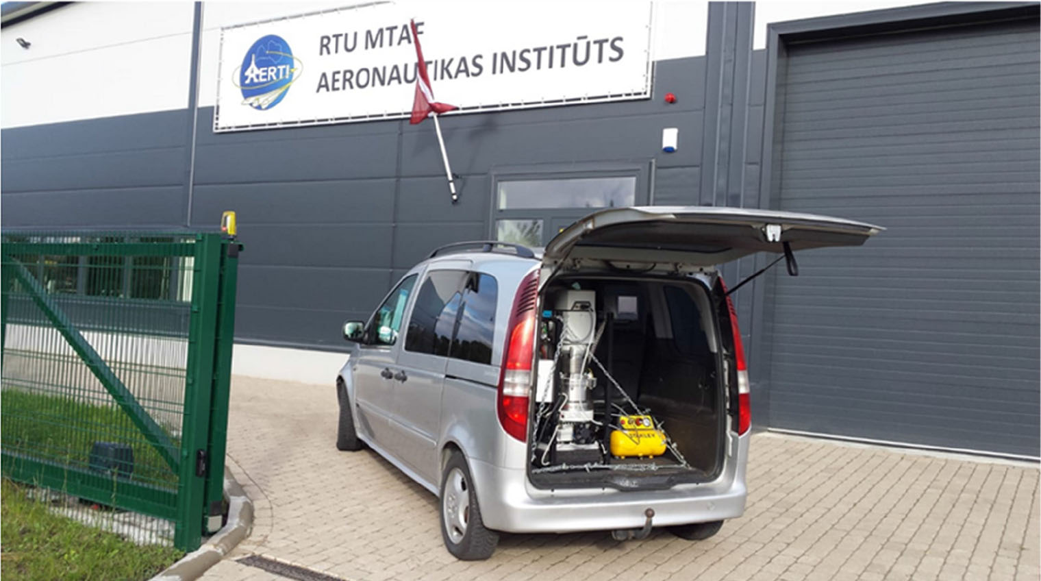
Fig. 1.
Mobile space environment simulator developed in a joint project between RTU and SIA Cryogenic and Vacuum Systems.
Table 1.
GSFC-STD-7000 Test requirements.
Vacuum, Thermal, and Humidity Requirements
| Requirement | Payload or Highest Practicable Level of Assembly | Subsystem including Instruments | Unit / Component |
|---|---|---|---|
| Thermal-Vacuum 1,6 | T | T | T2 |
| Thermal Balance 1,3,6 | T and A | T, A | T, A |
| Temperature-Humidity3 (Habitable Volumes) | T / A | T / A | T / A |
| Temperature-Humidity4 (Transportation & Storage) | A | T / A | T / A |
| Leakage5 | T | T | T |
[i] where T is the test required; A is the analysis required, tests may be required to substantiate the analysis; T/A is the test required if analysis indicates possible condensation; T, A is the test that is not required at this level of assembly if analysis verification is established for non-tested elements.
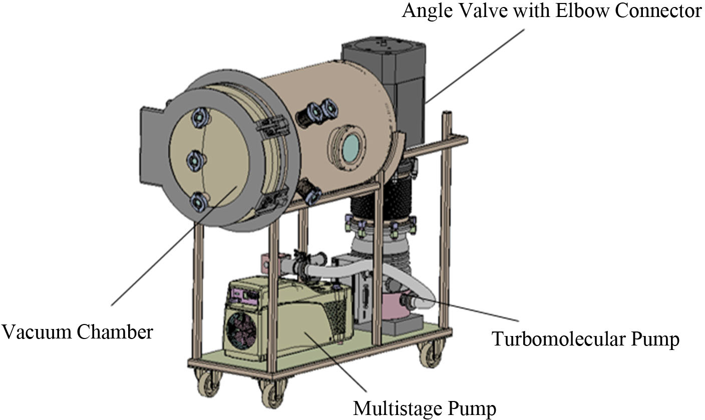
Fig. 2.
Vacuum system ‘METAMORPHOSIS’ for outer space simulating.
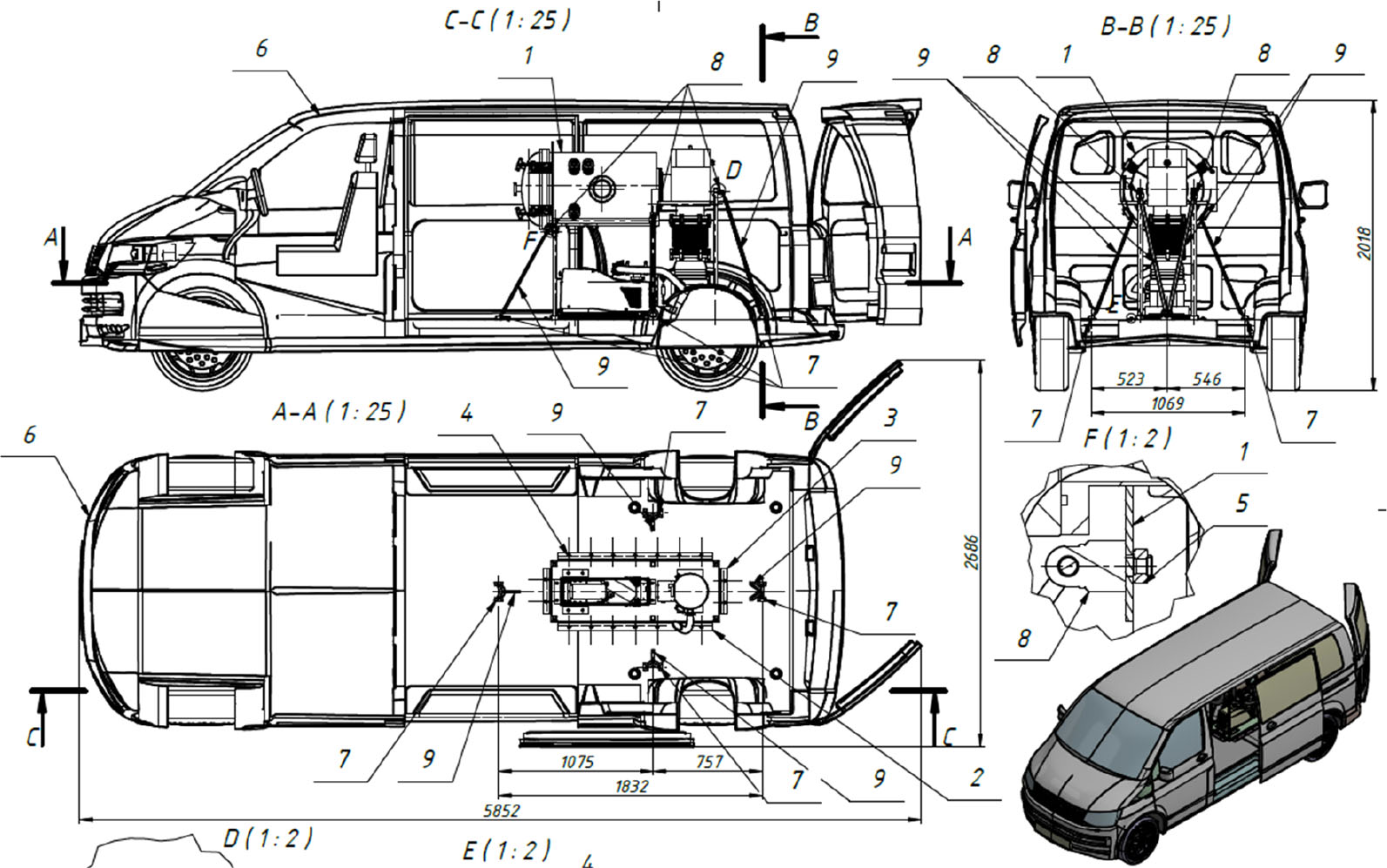
Fig. 3.
Vacuum system ‘METAMORPHOSIS’ is housed in a vehicle.
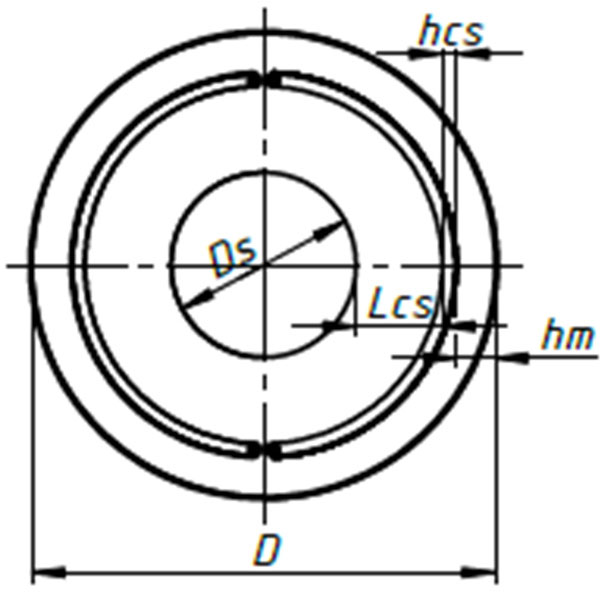
Fig. 4.
Determination of vacuum chamber diameter size.
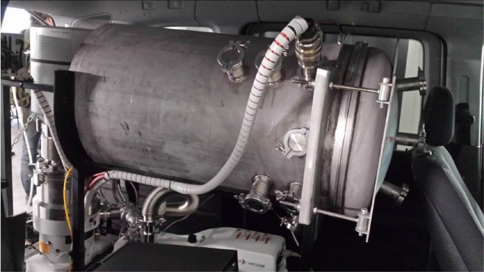
Fig. 5.
MSESF ‘METAMORPHOSIS’ vacuum pumping system including dry vacuum pump and cryogenic pump.
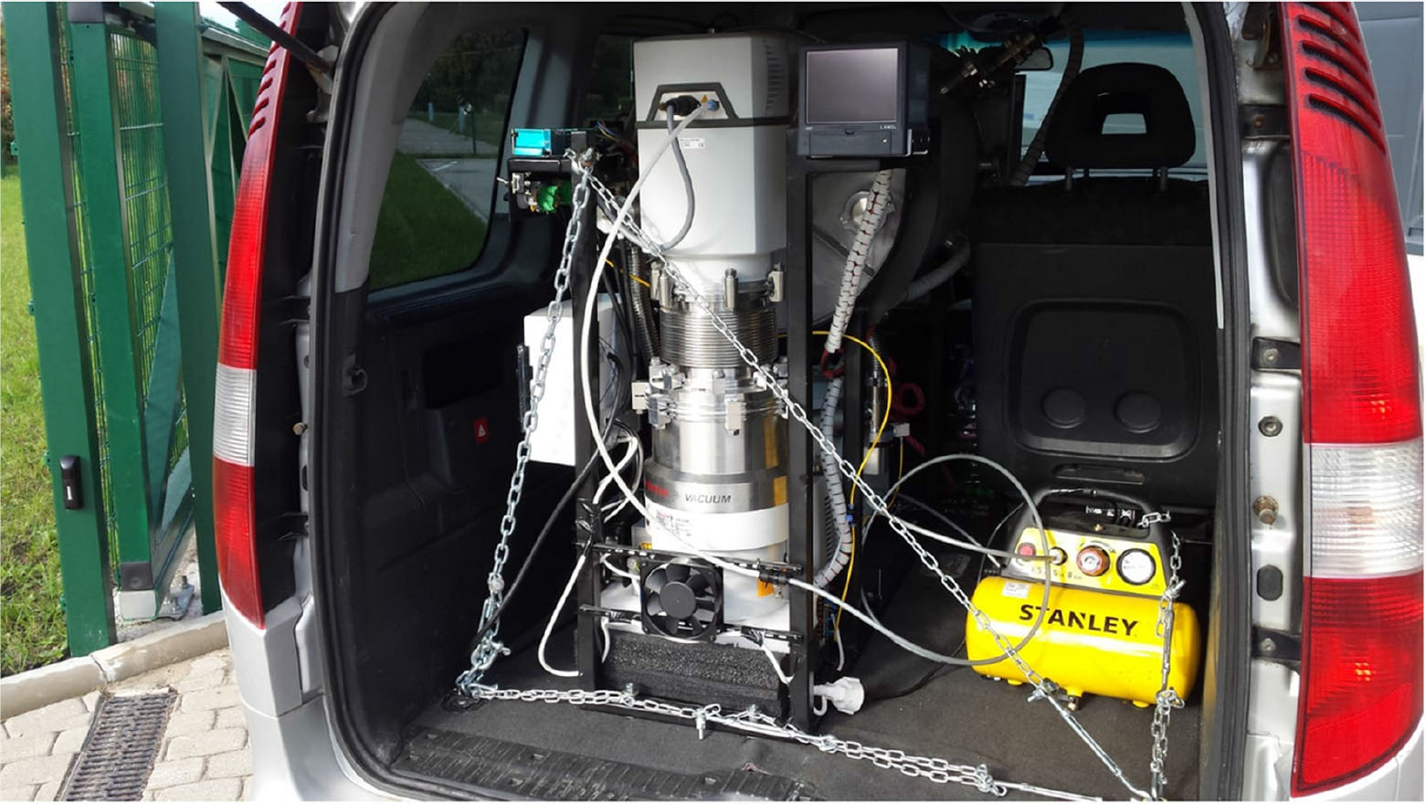
Fig. 6.
Mobile space environment simulation facility with control panels.
Table 2.
The initial data for calculations.
| Main part | Material | Diameter (Mm) | Thickness (mm) | Length (height), mm | Total increment, (mm) | Weld strength factor |
|---|---|---|---|---|---|---|
| The flat bottom | AISI-304 | 800 | 5 | 5 | 0,5 | 0,9 |
| The cylindrical shell | AISI-304 | 800 | 5 | 1300 | 0,5 | 0,9 |
| The elliptical cover | AISI-304 | 800 | 5 | 268 | 0,5 | 0,9 |
Table 3.
Operating conditions.
| Part | Design temp. (C) | Design pressure (MPa) | Permissible stresses (MPa) | Estimated thickness with increments (mm) | Permissible pressure (MPa) | Strength condition |
|---|---|---|---|---|---|---|
| The flat bottom | 30 | (0.1000) | 149 | 9.457 | 0.1097 | Satisfied |
| The cylindrical shell | 30 | (0.1000) | 149 | 3.849 | 0.2082 | Satisfied |
| The elliptical cover | 20 | (0.1000) | 150 | 2.137 | 0.6911 | Satisfied |
Table 4.
Test conditions.
| Part | Design pressure (MPa) | Permissible stresses (MPa) | Estimated thickness with increments (mm) | Permissible pressure (MPa) | Strength condition |
|---|---|---|---|---|---|
| The flat bottom | 0 | 230 | 0.5 | 0.1693 | Satisfied |
| The cylindrical shell | 0 | 230 | 0.5 | 2.316 | Satisfied |
| The elliptical cover | 0 | 230 | 0.5 | 2.322 | Satisfied |
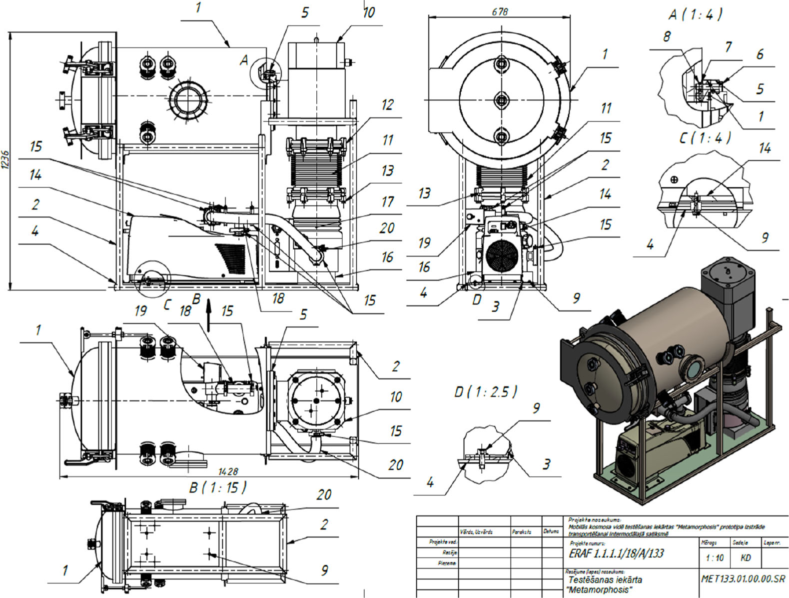
Figure 7:
Vacuum system’s drawing.