
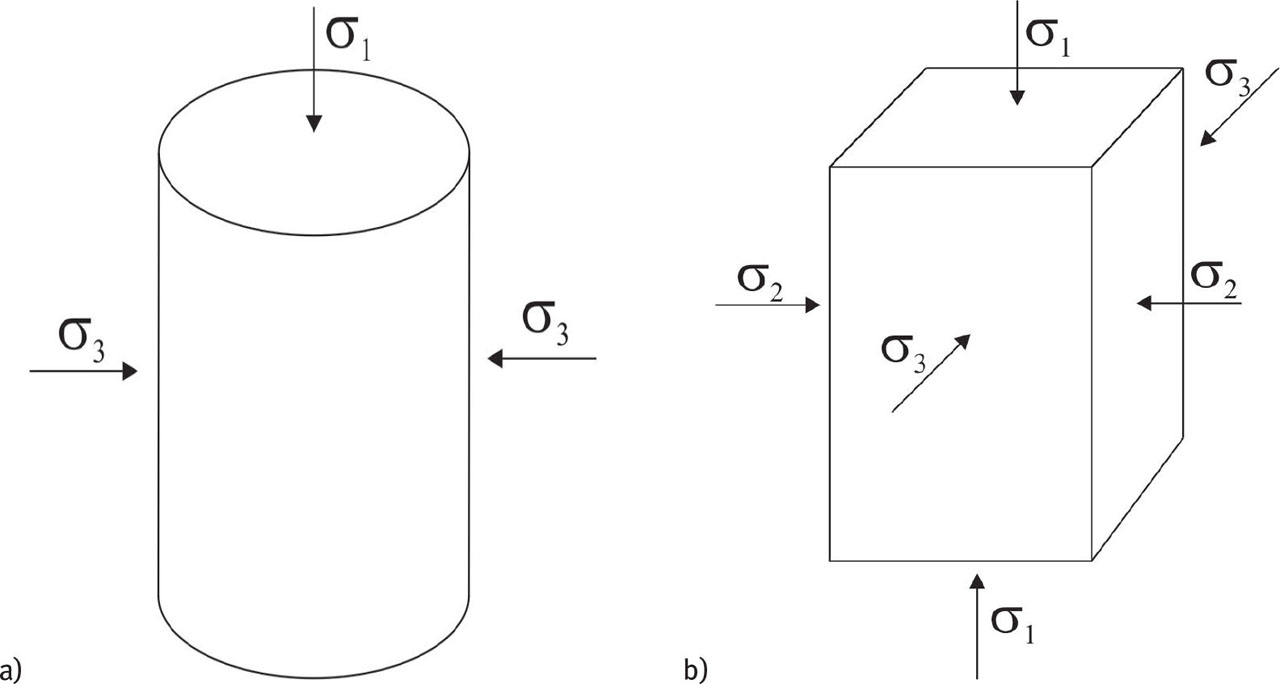
Figure 1
Two-dimensional and three-dimensional soil stress states: a) cylindrical sample in axisymmetric stress conditions, σ2 = σ3 and b) rectangular sample in true triaxial conditions, σ1 ≠ σ2 ≠ σ3.
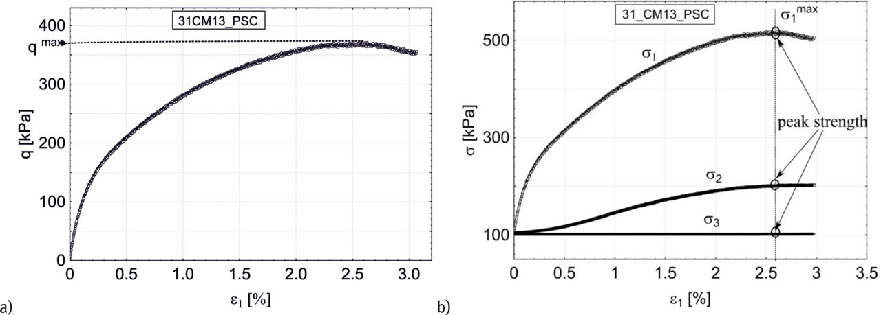
Figure 2
The principal stress and axial strain curves for the selected test in plane strain conditions: a) q(ɛ1) and b) σ1(ɛ1), σ2(ɛ1) and σ3(ɛ1).
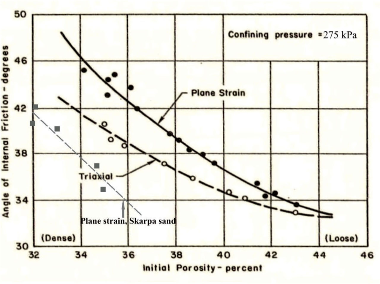
Figure 3
Comparison of the results from drained triaxial and plane strain tests on sand [18] and true-triaxial tests on Skarpa sand.
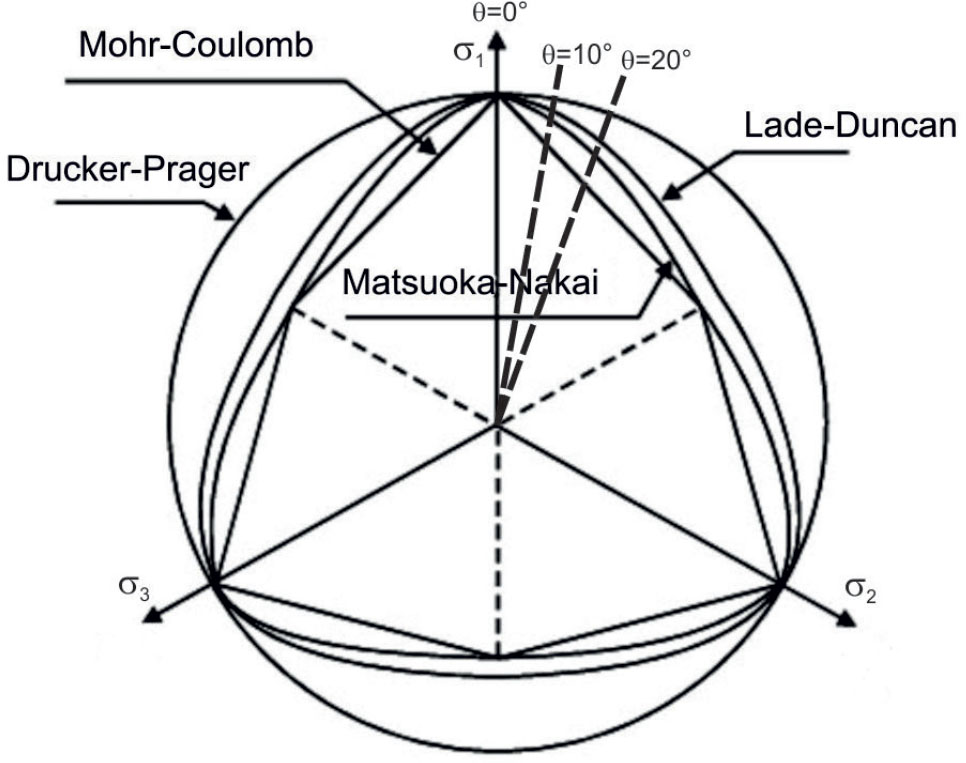
Figure 4
Failure surfaces in the deviatoric plane, see Georgiadis et al. (2004). In plane strain conditions, Lode angle varies roughly from θ = 10° to θ = 20°.
Table 1
Parameters of Skarpa sand.
| Specific density [kg/m3] | 2650 |
| Mean particle size [mm] | D50 - 0.42 |
| Uniformity coefficient [ − ] | U = 2.5 |
| Minimum void ratio [ − ] | emin = 0.432 |
| Maximum void ratio [ − ] | emax = 0.677 |
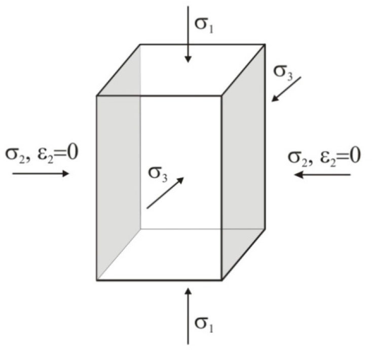
Figure 5
Layout of the soil sample under plane strain conditions in EMTTA.
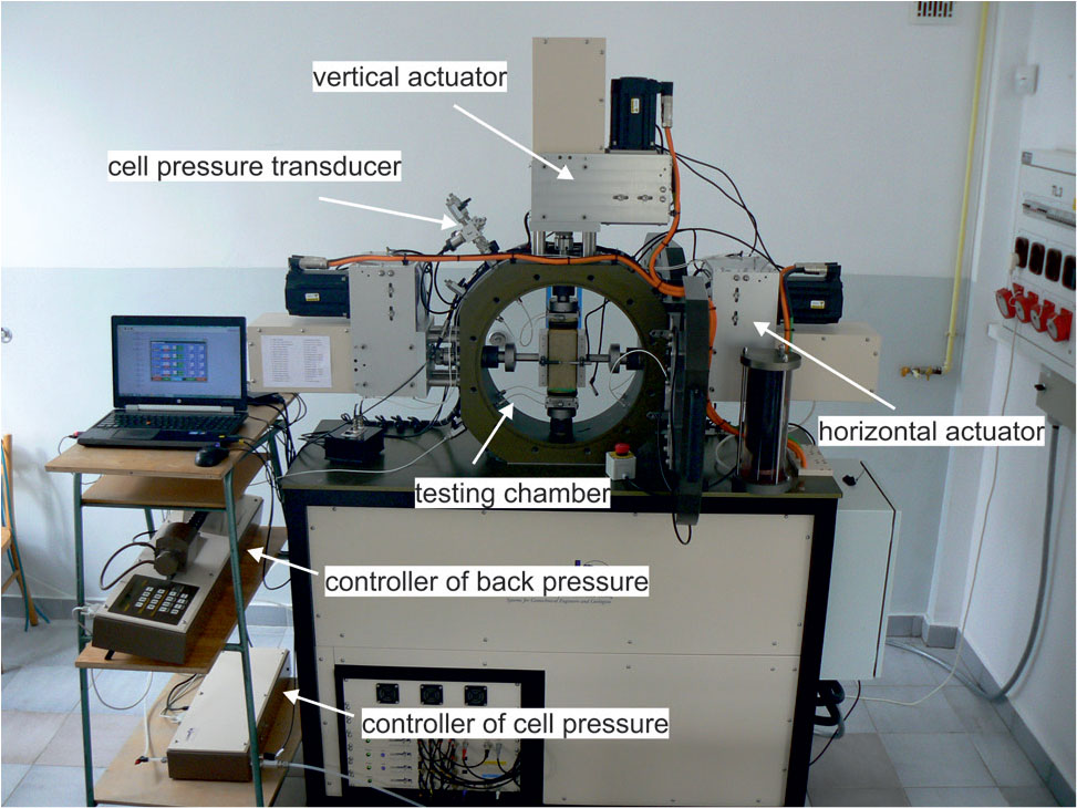
Figure 6
Components of EMTTA, used in the study.
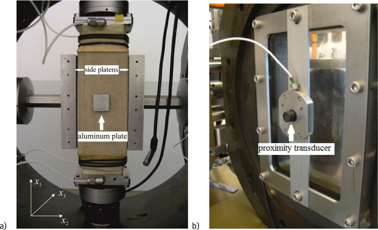
Figure 7
a) The GDS EMTTA chamber with a sample prepared for the test. The role of the side plates is to prevent soil deformations in the x2direction, b) proximity transducer on the doors of the measurement cell (test chamber).
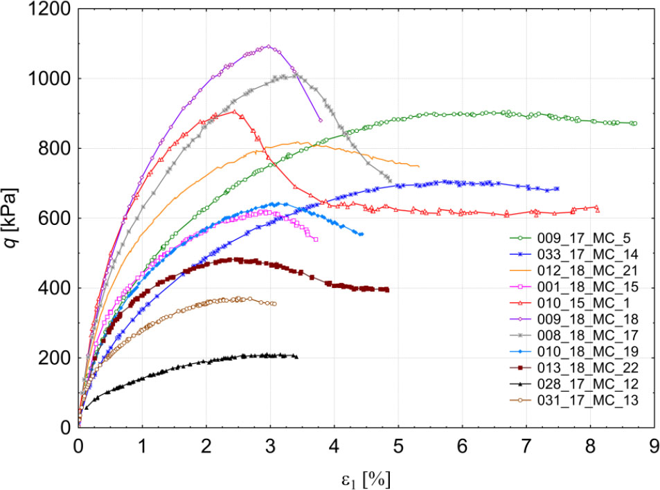
Figure 8
Results of the experimental tests listed in Table 1: deviator stress as a function of the axial strain q(ɛ1).
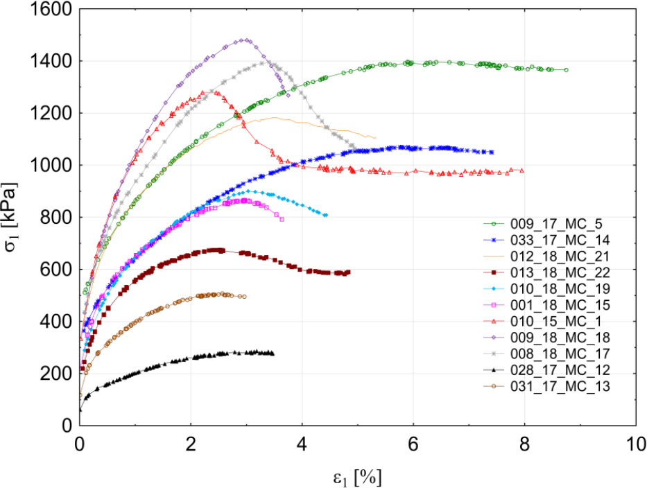
Figure 9
Results of the experimental tests listed in Table 1: maximum principal stress as a function of the axial strain σ1(ɛ1).
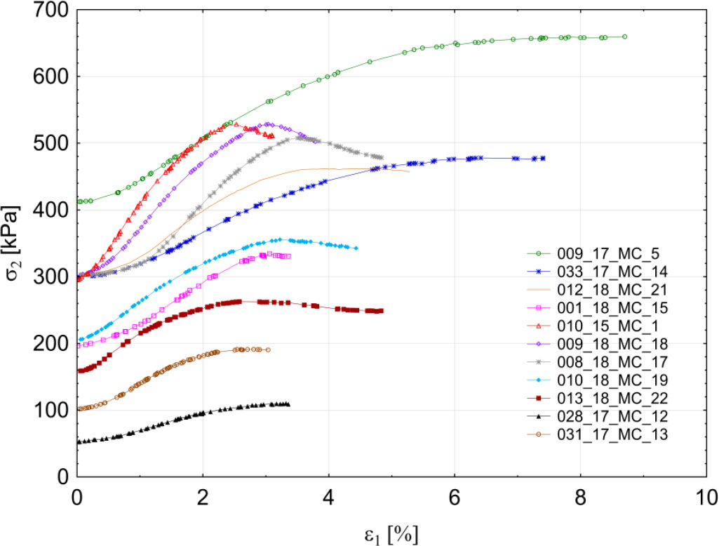
Figure 10
Results of the experimental tests listed in Table 1: principal stress in the direction of fixed strain (ɛ2 = 0) as a function of the axial strain σ2(ɛ1).
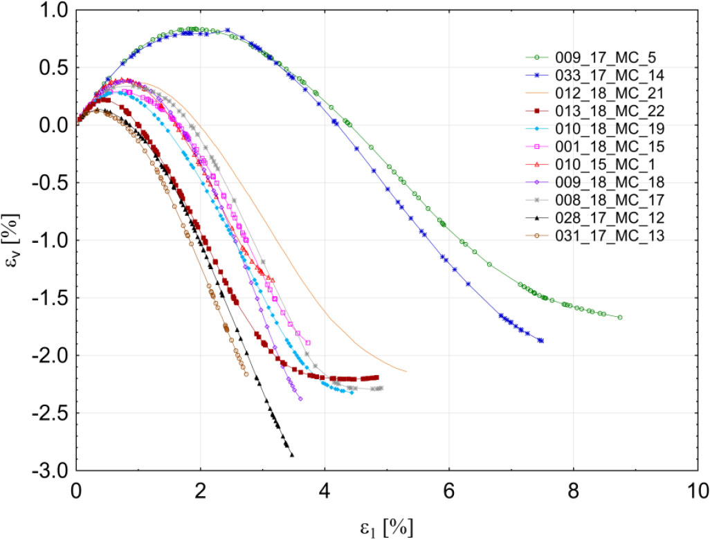
Figure 11
Results of the experimental tests listed in Table 1: volumetric strain as a function of the axial strain ɛv(ɛ1).
Table 2
Initial test conditions.
| Test | e | ID | σc3[kPa] | ec | nc | |
|---|---|---|---|---|---|---|
| 009_17_MC_5 | 0.585 | 0.376 | 391 | 0.563 | 0.465 | 0.36 |
| 033_17_MC_14 | 0.559 | 0.482 | 293 | 0.548 | 0.527 | 0.354 |
| 012_18_MC_21 | 0.541 | 0.555 | 292 | 0.532 | 0.592 | 0.347 |
| 013_18_MC_22 | 0.519 | 0.645 | 146 | 0.514 | 0.665 | 0.339 |
| 010_18_MC_19 | 0.517 | 0.653 | 195 | 0.508 | 0.690 | 0.337 |
| 001_18_MC_15 | 0.521 | 0.637 | 191 | 0.499 | 0.727 | 0.333 |
| 010_15_MC_1 | 0.496 | 0.739 | 278 | 0.490 | 0.763 | 0.329 |
| 009_18_MC_18 | 0.488 | 0.771 | 292 | 0.480 | 0.804 | 0.324 |
| 008_18_MC_17 | 0.489 | 0.767 | 295 | 0.476 | 0.820 | 0.322 |
| 028_17_MC_12 | 0.467 | 0.857 | 52 | 0.462 | 0.878 | 0.316 |
| 031_17_MC_13 | 0.469 | 0.849 | 99 | 0.462 | 0.878 | 0.316 |
Table 3
Characteristics of peak strength state for the tested samples.
| Test | σ1max [kPa] | σ2 [kPa] | σ3 [kPa] | p [kPa] | q [kPa] | b [ − ] | θ [ ° ] |
|---|---|---|---|---|---|---|---|
| 009_17_MC_5 | 1402 | 653 | 391 | 815 | 909 | 0.26 | 14.46 |
| 033_17_MC_14 | 1072 | 479 | 293 | 615 | 705 | 0.24 | 13.21 |
| 012_18_MC_21 | 1184 | 459 | 292 | 645 | 821 | 0.19 | 10.14 |
| 013_18_MC_22 | 678 | 262 | 146 | 362 | 485 | 0.22 | 11.97 |
| 010_18_MC_19 | 902 | 355 | 195 | 484 | 642 | 0.23 | 12.46 |
| 001_18_MC_15 | 870 | 332 | 191 | 464 | 621 | 0.21 | 11.35 |
| 010_15_MC_1 | 1291 | 529 | 278 | 699 | 914 | 0.25 | 13.76 |
| 009_18_MC_18 | 1483 | 528 | 292 | 768 | 1092 | 0.20 | 10.78 |
| 008_18_MC_17 | 1396 | 506 | 295 | 732 | 1012 | 0.19 | 10.40 |
| 028_17_MC_12 | 287 | 109 | 52 | 149 | 212 | 0.24 | 13.44 |
| 031_17_MC_13 | 508 | 191 | 99 | 266 | 372 | 0.22 | 12.38 |
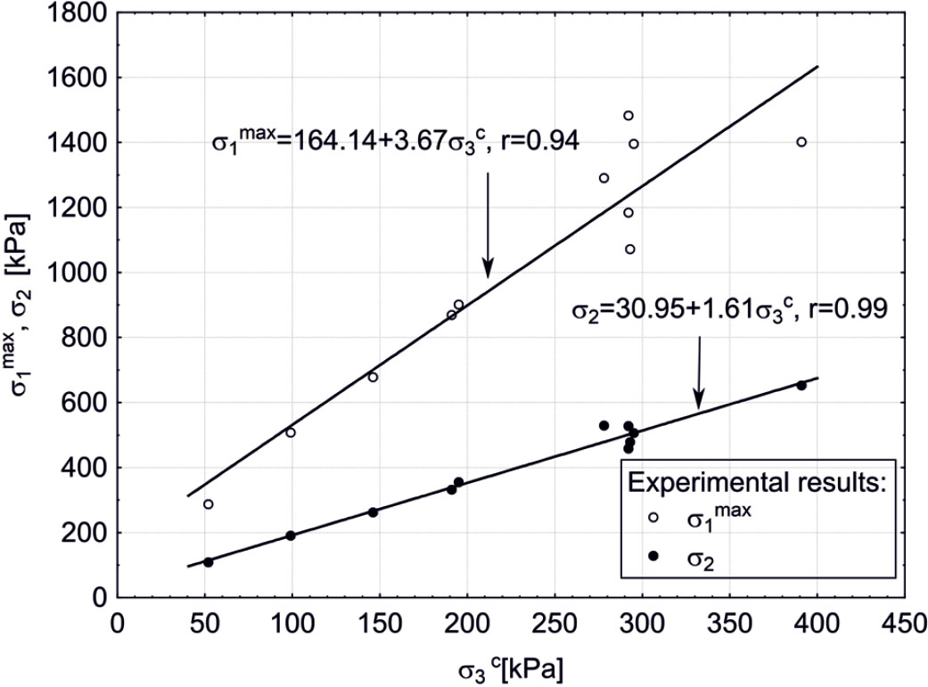
Figure 12
Relations between principal stress components, corresponding to peak soil strength: σ1max (σ3) and σ2(σ3).
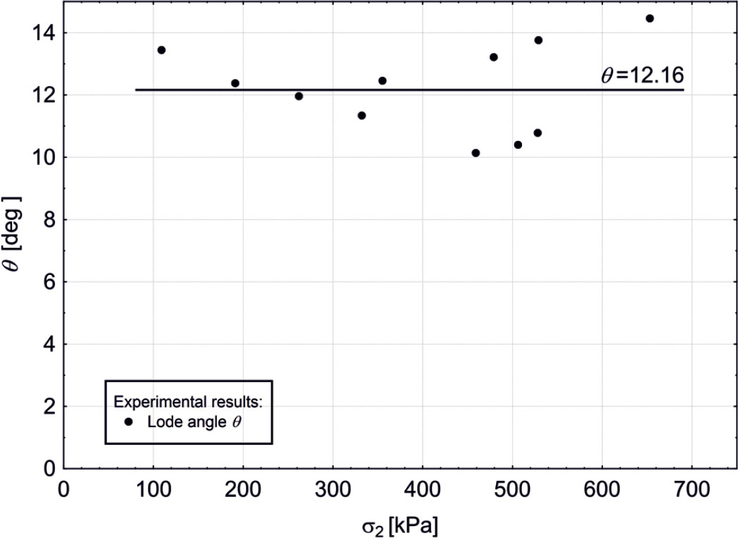
Figure 13
Relation between Lode angle θ and intermediate stress σ2.
Table 4
Characteristic parameters of Drucker–Prager, Matsuoka–Nakai and Lade–Duncan soil failure criteria, obtained from direct stress measurements (A) and the associated flow rule assuming plane strain conditions (B).
| Test | A. Direct stress measurements Eqs. (15)–(18) | B. Flow rule and plane strain condition Eqs. (25)–(27) | ||||||||
|---|---|---|---|---|---|---|---|---|---|---|
| ϕps | ||||||||||
| 009_17_MC_5 | 34.3° | 0.21 | 11.7 | 40.9 | 1181.5 | 740.4 | 896.5 | 0.179 | 11.7 | 39.6 |
| 033_17_MC_14 | 34.8° | 0.22 | 11.9 | 41.7 | 904.8 | 560.4 | 682.5 | 0.181 | 11.8 | 40.0 |
| 012_18_MC_21 | 37.2° | 0.25 | 12.5 | 45.7 | 1007.5 | 588.0 | 738 | 0.190 | 12.3 | 42.5 |
| 013_18_MC_22 | 40.2° | 0.26 | 13.2 | 49.4 | 583.8 | 314.6 | 412 | 0.202 | 13.1 | 46.3 |
| 010_18_MC_19 | 40.1° | 0.26 | 13.1 | 49.0 | 776.3 | 419.3 | 548.5 | 0.201 | 13.1 | 46.2 |
| 001_18_MC_15 | 39.8° | 0.26 | 13.1 | 49.0 | 747.8 | 407.6 | 530.5 | 0.200 | 13.0 | 45.7 |
| 010_15_MC_1 | 40.2° | 0.25 | 13.1 | 48.6 | 1111.5 | 599.1 | 784.5 | 0.202 | 13.1 | 46.3 |
| 009_18_MC_18 | 42.1° | 0.27 | 13.8 | 53.4 | 1287.1 | 658.1 | 887.5 | 0.209 | 13.7 | 49.1 |
| 008_18_MC_17 | 40.6° | 0.27 | 13.4 | 50.9 | 1203.9 | 641.7 | 745.5 | 0.203 | 13.2 | 46.9 |
| 028_17_MC_12 | 43.9° | 0.27 | 14.3 | 55.3 | 251.0 | 122.1 | 169.5 | 0.215 | 14.3 | 52.0 |
| 031_17_MC_13 | 42.4° | 0.27 | 13.8 | 52.9 | 441.3 | 224.3 | 303.5 | 0.209 | 13.7 | 46.5 |
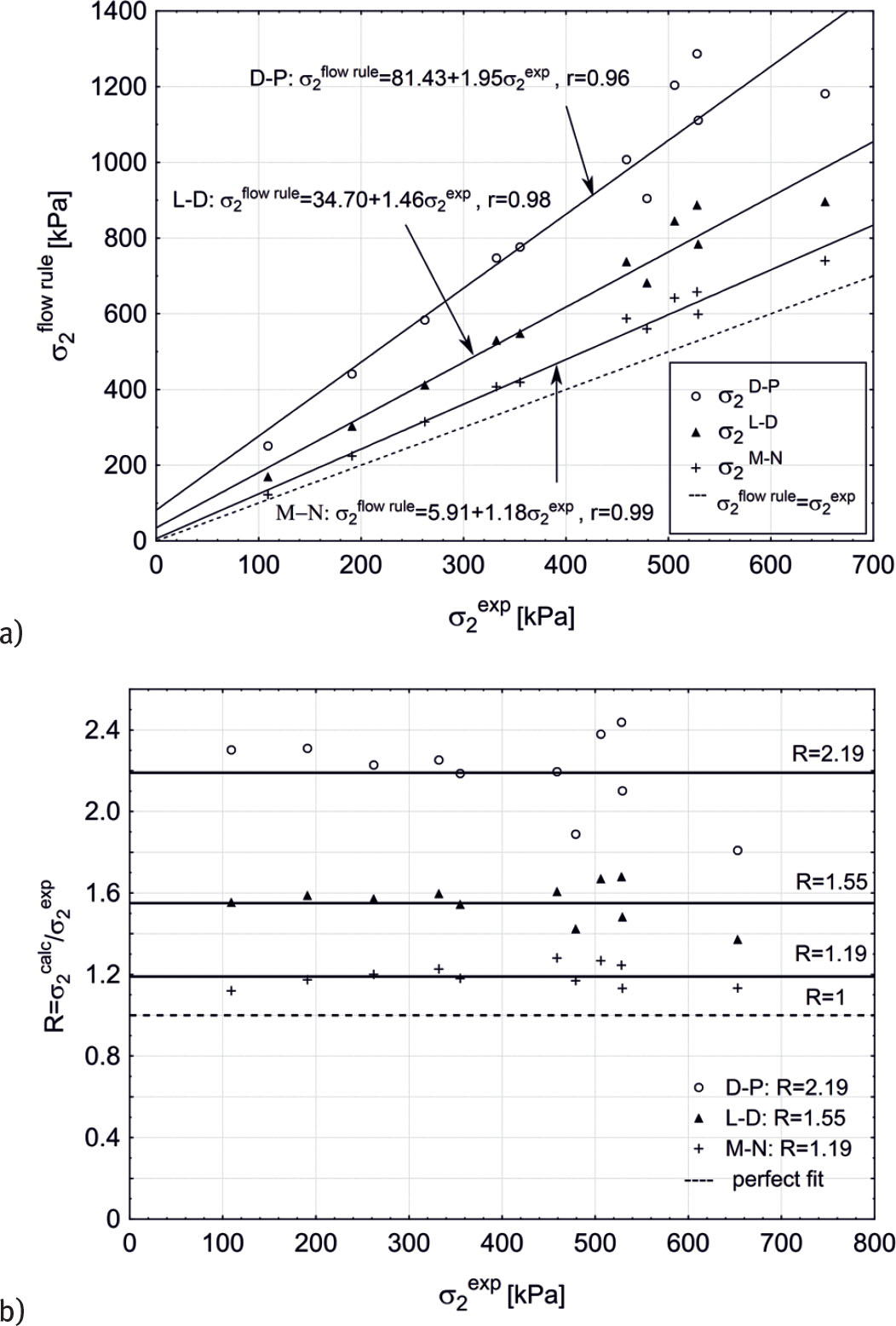
Figure 14
The intermediate stress σ2, obtained for Drucker–Prager (D-P), Matsuoka–Nakai (M-N) and Lade–Duncan (L-D) failure criteria, assuming plane strain condition and the associated flow rule, as function of the measured σ2 (Table 3): (a) σ2calc (σ2exp) and (b) R(σ2exp), where R = σ2calc/σ2exp.
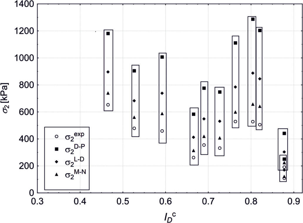
Figure 15
Dependence of the intermediate stress σ2 (Tables 3 and 4) on the initial relative density of Skarpa sand.
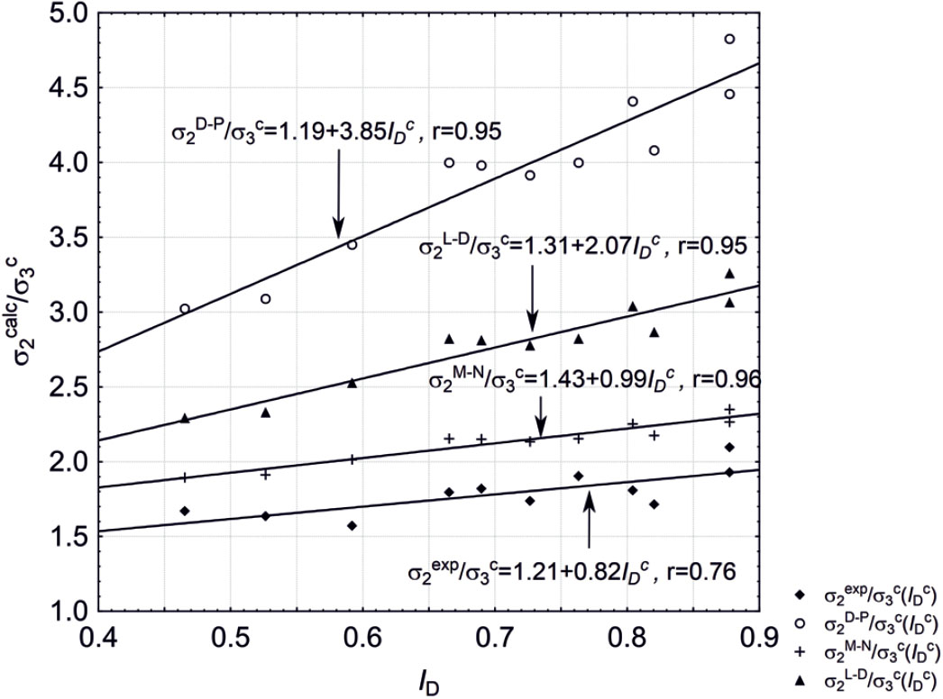
Figure 16
Dependence of the ratio of intermediate stress σ2 to confining pressure σ3 (Table 4) on the initial relative density of Skarpa sand.
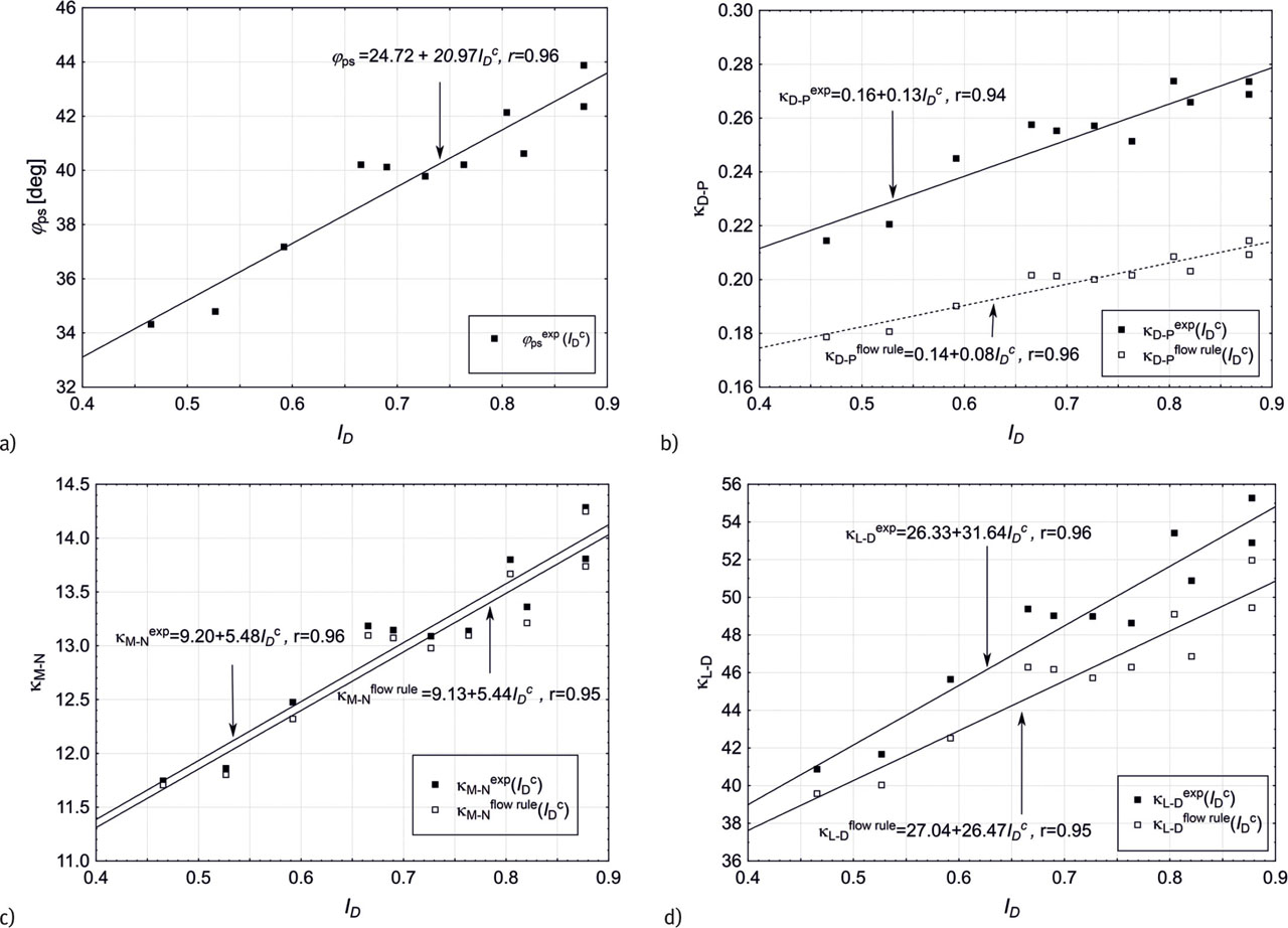
Figure 17
Parameters of Mohr–Coulomb (M-C), Drucker–Prager (D-C), Matsuoka–Nakai (M-N) and Lade–Duncan (L-D) failure criteria depending on soil relative density: (a) friction angle ϕ, (b)–(d) comparison of κD-P, κL-D and κM-N, obtained by Eqs. (16)–(18) (full stress state measurement) and Eqs. (25)–(27) (plane strain condition – Vikash and Prashant approach).
Table 5
The linear fits and the corresponding Pearson's correlation coefficients.
| Linear fit | Pearson's coefficient r | |
|---|---|---|
| Drucker–Prager | rD-P = 0.94 | |
| Lade–Duncan | rL-D = 0.96 | |
| Matsuoka–Nakai | rM-N = 0.96 |
Table 6
The linear fits κexp(ϕps)and the corresponding statistics Pearson's correlation coefficients.
| Linear fit | Pearson's coefficient r | |
|---|---|---|
| Drucker–Prager | rD-P = 0.970 | |
| Lade–Duncan | rL-D = 0.993 | |
| Matsuoka–Nakai | rM-N = 0.997 |
Table 7
Average relative difference of parameters κ and intermediate principal stress σ2, determined by the two approaches: full set of principal stresses and Vikash and Prashant proposal, for Drucker–Prager, Lade–Duncan and Matsuoka–Nakai failure criteria.
| vκ | vσ2 | |
|---|---|---|
| Drucker–Prager | ||
| Lade–Duncan | ||
| Matsuoka–Nakai |