
1. Introduction
Quantum algorithms has become an attractive field of practical realization of quantum physics in everyday life. Among other quantum algorithms we concentrate on the family of algorithms manipulating with matrices and thus representing the quantum analogues of classical counterparts. Quantum Fourier transform [1–3] and phase estimation [3,4] must be distinguished as most popular and well recognized quantum algorithms used as subroutines included in many algorithms for data processing.
Set of algorithms reaches the goal using exclusively quantum approach. Apart from Fourier transform and Quantum phase estimation quoted above we refer to the algorithms for matrix manipulations (addition, multiplication, Kronecker sum, tensor product, Hadamard product) based on the Trotterization method [5–8] and the Baker-Champbell-Hausdorff [9] approximation for exponentiating matrices [10]. In [11], the matrix operations (addition, multiplication, inner product of vectors) are realized via action of special unitary operations on the matrix encoded into the either mixed or pure superposition state of some quantum system. Later, such unitary transformations where realized in terms of simple one- and two-qubit operations [12]. The matrix-encoding approach was implemented in the quantum algorithms for determinant calculation, matrix inversion and solving linear systems [13].
Another large family of algorithms includes algorithms combining both quantum and classical subroutines. To such algorithms one can refer the original version of the well-known Harrow-Hassidim-Lloyd (HHL) algorithm for solving systems of linear algebraic equations [14–21]. In this algorithm the classical subroutine is required for inversion of eigenvalues λj of the matrix A in equation Ax = b. However, later the method of approximate calculation of the inverse eigenvalues 1/λj was developed [22,23]. This method can be incorporated into HHL algorithm removing necessity of classical operations. Variational algorithms represent widely acknowledged class of hybrid algorithms for solving problems based on optimization methods. In particular, such algorithm was developed for the singular value decomposition (SVD) [24–27], where the loss (or objective) function at fixed optimization parameters was calculated by the quantum algorithm, while the iteration of parameters was performed using the classical gradient method. In Ref. [26], all simulations were implemented via Paddle Quantum [28] on the PaddlePaddle Deep Learning Platform [29,30].
We have to note that some principal issues on quantum algorithms for SVD are referred to Refs. [31–34]. Thus, the principle of realization of the quantum gradient descent algorithm is described in [31], but no explicit representation for unitary transformation performing iteration steps in this algorithm is given, this problem requires further study. In [32], the problem of fixing the phase of the singular vector associated with the appropriate singular value is explored. The data analysis involving the quantum SVD-based data representation is proposed in [33]. The quantum singular value estimation algorithm (i.e., estimation of the singular value associated with each singular vector) is described in [31,34]. However, the particular realizations of quantum algorithm are not discussed there. This fact motivates research on development of quantum SVD algorithms which can be validated on near-term quantum processors. The importance of the algorithms for SVD is determined by the wide applicability of SVD as a subroutine in various algorithms including some variants of matrix inversion [22,23], solving systems of linear equations [35], quantum recommendation systems [31,36,37].
In our paper, we modify the algorithm developed in [26,27] implementing the encoding the elements of the N × N matrix A into the probability amplitudes of the pure state of some quantum system with subsequent application of two parametrized unitary transformations and matrix multiplications using the algorithm proposed in [12]. Implementing this encoding we avoid representation of A as a linear combination of unitary transformations utilized in [26,27]. In comparison with the above references, we reduce the number of measurements required to get the complete information for calculating the objective function. In our case, each run of the algorithm is supplemented with O(1) measurements of the uncillae states (subsystems K and B below), while the number of measurements in [26,27] is O(N), here N is the number of diagonal elements in the considered matrix. Of course, because of the probabilistic method of obtaining the objective function, one has to perform series of runs of the algorithm.
The paper is organized as follows. In Section 2 we present the detailed description of our version of the quantum part of the variational SVD and briefly discuss the complete hybrid algorithm. Conclusions are given in Section 3.
2. Singular Value Decomposition
2.1. Preliminaries
We consider the singular value decomposition of an arbitrary square N × N matrix M assuming N = 2n,
where D = diag(d1, …, dN) is the diagonal matrix of singular values (some of those values might be zero) and Û and are unitary matrices. To find the singular values (entries of the diagonal matrix D) we, first of all, introduce the following objective function [26]: where |ψj〉, j = 0, …, N − 1, is a set of orthogonal vectors, α = {α0, …, αnQ} and β = {β0, …, βnQ} represent two sets of optimization parameters, q0 > ⋯ > qN−1 are real weights, Q is some integer associated with the subroutine used for preparing the unitary transformation U in Section 2.3. We also note that the sum in (2) is over all N singular values including possible zeros unlike Ref. [26], where the sum is truncated keeping only T ≤ N largest singular values. This truncation can be simply realized in our algorithm just equating to zero all qj with j > T. The reason to take transposition T of the matrix U in (2) will be clarified letter, see eq. (23). Here we emphasize that, although the objective function is a sum of N terms, its expectation value will be found by measuring the states of two qubis, see eqs. (29), (30), unlike Refs. [26,27], where the expectation value of each term must be measured separately. We appeal to the gradient method to find such parameters α* and β* that maximize the objective function, i.e.,Then
As for the set of orthogonal vectors |ψj〉, we take the vectors of computational basis |j〉, j = 0,…, N – 1, where the integer j is written in the binary form. We introduce five n-qubit subsystems, see Figure 1: the subsystems R and C serve to enumerate, respectively, the rows and column of M, the subsystems χ and ψ are needed to operate with 〈ψj| and |ψj〉 in (2), these two subsystems are also used to organize the weighted sum over j in (2), and the subsystem q encodes the normalized vector of weights,
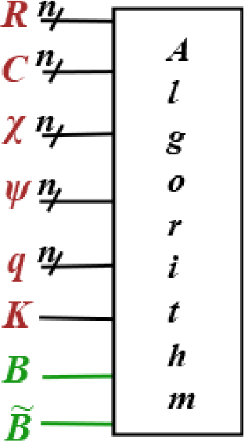
Figure 1.
Structure of subsystems required for performing the quantum part of variational SVD. It includes five n-qubit subsystems for encoding the matrix M(subsystems R, C), orthonormal eigenvectors 〈ψj| and |ψj〉 (subsystems χ, ψ) and weights qi (subsystem q). In addition, the one-qubit subsystem K serves as a controlling qubit in controlled operators of the algorithm and two one-qubit ancillae B and serve for the controlled measurement.
In addition, the single qubit of the subsystem K serves as a controlling qubit in succeeding controlled operations. At the last steps of the algorithm we will introduce two one-qubit ancillae B and to properly organize garbage removal and required measurements.
We shall note that the proposed method can be also used to construct the eigensystem for the square positive semidefinite matrix R (for instance, for the density matrix), i.e., we can factorize R as R = UDU†. For this purpose, we just have to involve the following relation between the matrices U(α) and U(β):
where the bar means complex conjugate. This condition can be simply satisfied in the case when all the parameters αj and βj are introduced via the x-, y-, or z-rotation Rθj = e–σ(θ)αj/2, θ = x, y, z, σ(θ) are the Pauli matrices. If θ = y, then αj = βj. In the case θ = x, z, we take αj = –βj.2.2. Quantum Algorithm Preparing Objective Function
First of all, we have to prepare the above mentioned matrix M = {mij : i, j = 0, …, N – 1} for encoding into the state of a quantum system. To this end we normalize M and make real the first diagonal element assuming that this element does not equal to zero (m00 ≠ 0), i.e., replace M with the matrix A = {aij : i,j = 0, …, N – 1}:
Now we can encode the elements of the matrix A into the superposition state of R and C as follows:
where the normalization is provided by eq. (7). In other words, we have quantum access to the matrix A [33]. Here we shall note that the matrix encoding problem is a complicated task by itself and, in general, the depth of the algorithm encoding the N × N matrix is at least O(N2). The same holds for encoding the state |φ〉q in (5). However, both this problems can be referred to the initial state preparation and will not be detailed in our paper. Subsystems χ, ψ and K are in the ground state initially and the state of q is defined in (5), i.e., the initial state of the whole system reads:Hereafter in this paper the subscript means the subsystem to which the operator is applied.
Now we proceed to description of the quantum algorithm, which is also illustrated by the circuit in Fig.2. As the first step, we apply the Hadamard transformation to each qubit of χ and K (we denote this set of transformations as :
thus creating the systems of orthonormal states |k〉χ, k = 0, …, N – 1, and initializing the superposition state of the controlling qubit K.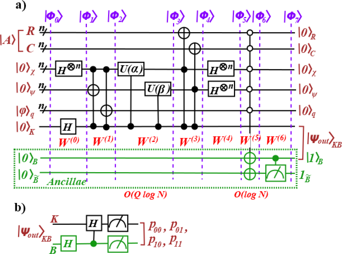
Figure 2.
The circuit for the quantum part of the variational SVD algorithm. The depth of this circuit can be estimated as O(Qlog(N)/ε). (a) The circuit for creating the state |ψout〉K given in (27); the operatorsW(j), j = 0, …,6 are presented without subscripts for brevity. (b) The operators applied to the state |ψout〉KB to probabilistically obtain the normalization G and the objective function L(α, β).
Now we double the state |k〉χ creating the same state |k〉ψ of the system ψ and also multiply the obtained state by the weight qk resulting in qk|k〉χ|k〉ψ|0〉q, see eq. (13). In the last case we use the trick proposed in [13] for matrix product. Both operations are controlled by the state of K, i.e., they are applied only if K is in the excited state |1〉K. To arrange such control we introduce the projectors
and the controlled operatorHereafter the subscript attached to the notation of a subsystem indicates the appropriate qubit of this subsystem. Thus, subscript i mean the ith qubit of the appropriate subsystem in (12).
Applying we obtain
where the garbage |g2〉 collects the terms containing the states |j〉q with j > 0, which we don’t need hereafter.Next, we prepare and apply the unitary operators U(α) and U(β) in (2) controlled by the excited state of the one-qubit subsystem K:
We can represent the action of the operator U on the vectors |k〉χ and |k〉ψ in terms of its elements as follows:
Then, applying to |Φ2〉 we obtain
Here, the garbage |g2〉 from (13) is transformed to |g3〉, but we don’t describe explicitly this transformation because we are not interested in the particular structure of the garbage. The same holds for the garbage in other states below. To multiply three matrices , A and Uψ(β) and eventually calculate the sum Σj qj 〈j|UT(α)AU(β)|j〉ψ in (2), we follow Refs. [12,13]. Using projectors (11) and projectors
we introduce the following controlled operators:Here, the operator is required for multiplying UT(α) and A, the operator serves for multiplying A and U(β), Applying the operator to the state |Φ3〉 we obtain
where the first part in the rhs collects the terms needed for further calculations (these terms will be labelled later on by the operator , see eq. (24)) and |g4〉 is the garbage to be removed later. Now, according to the multiplication algorithm (see Appendix in Ref. [13]) we introduce the operator where Hχ and Hψ are the sets of Hadamard transformations applied to each qubit of the subsystems χ and ψ respectively. These operators complete the multiplications UT(α)A and AU(β) respectively, and simultaneously calculate the weighted trace Σj qj(UT(α)AU(β))jj. Then, applying to the state |φ4〉, selecting only the needed terms and moving others to the garbage |g5〉, we obtain where,Remark that the factor 2n in the expression for ã00 (22) appears because of the sum over k in (19) which includes n terms.
Now we label and remove the garbage |g5〉 from the state (21) via the controlled measurement. To this end we introduce two one-qubit ancillae B and in the ground state and the controlled operator
Then, applying to the state we obtain
Now we can remove the garbage by introducing the controlled measurement [38],
where is the measurement operator applied to . Applying to |Φ6〉 we obtain where and we recall that ã00 in (22) is real because a00 is the real element of the matrix A and q0 is a positive integer.Remark 1.
To obtain the output state |ψout〉KB we involve so-called controlled measurement. Of course, we could obtain this state just using multiple running of the algorithm each time measuring the state of the ancilla till obtaining the state as the required result of measurement. In this case we again obtain the state |Φ7〉 (27) with the output state |ψout〉KB. However, the probability of such output of the measurement is O(2–(3n+1)) which exponentially decreases with the number of qubits n characterizing the space of the circuit. This is a disadvantage of the algorithm that can be completely overcome referring to the controlled measurement. Although we can not present a particular realization of this operator in terms of well-known quantum and/or classical operations, the controlled measurement reflects the deep relation between the quantum and classical physics. The measurement of state of the qubit will be performed if only the excited state |1〉B exists in the considered superposition state. Since our superposition state |Φ6〉 (25) includes |1〉B by construction, the measurement must be performed with the predictable result . In addition, the controlled measurement is the last element in the following scheme. We know the controlled operations, where both controlling and controlled subsystems are quantum (CNOT is the simplest representative). The controlled operations with controlling classical subsystem and controlled quantum subsystem are also acknowledged [3]. The proposed concept of controlled measurement represent the last possible type of control operations in quantum-classical system with the control by the state of a quantum subsystem. All these arguments do not prove realizability of controlled measurement but motivate the research for its realization that would not contradict the basic postulates and theorems of quantum mechanics including the no-cloning theorem [39].
We are aimed at finding the objective function L and normalization G. To this end we apply the Hadamard transformation HB to the ancilla B and then apply the Hadamard transformation HK, controlled by the excited state of B, to the qubit K, i.e., the controlled operator
Thus, we have
Now we measure the both qubits K and B with probabilities pij for fixing the state , i, j = 0,1, thus having
From this system we obtain the expressions for the needed quantities:
The depth of the operator can be estimated as O(log N) which is indicated in Figure 2. But the depth of the whole algorithm is defined by the operator whose depth is also indicated in Figure 2 and equals O(Qlog N). This estimation will be obtained in Section 2.3 after introducing the parameter Q. However, as for the depth of the whole algorithm for calculating the objective function, one can take into account the probabilistic method implemented for calculating the objective function using formula (32) that includes probabilities pij (i, j = 0, 1) given in (30). If the number of runs is Nr, then the depth of the algorithm is O(NrQlogN). In turn, Nr ~ 1/ε, where ε ≪ 1 is the required precision for the probabilistic calculation of pij. Therefore, the depth is O(Olog(N)/ε). We have to note that, also expression (32) for the objective function L has p00 in the denominator, there is no singularity at p00 → 0, because (p01 – p11) → 0 as well in this case. However, to provide calculation with required precision ε, we require p00 ≫ ε. This condition can be replaced by the following one:
In this case p00 ~ p01 ~ p11 ≫ ε, while the probability p10 does not appear in (32). If the probabilities p00, p01 and p11 are calculated with the precision ε, then formula (32) yields the objective function L with the precision ~ ε. Then, according to eq. (2), we conclude that the singular values can be calculated with the precision ~ ε/N.
Now we turn to the case when the condition (33) is destroyed and consider the case . In particular, ã can be zero. This is the case when we cannot use formulae (30)-(32) for calculating the objective function with precision e and we have to modify the algorithm. The simplest way is to change the starting point of the algorithm and replace formulae (9) and (10) with the following one:
After proper modification of the algorithm we result in the formulae similar to (30) in which the parameter ã00 is replaced with another parameter that does not depend on the elements of A and q. Such formulae allow to calculate the objective function L with any desired precision e. Further details of the modified algorithm will not be discussed here. We note that starting equation (34) can be used in case (33) as well. However, initial state (9) is simpler for preparation in comparison with state (34) and therefore it is recommended in case (33).
The space required for realization of this algorithm in both above cases is O(log N) qubits.
2.3. Realization of Operator for Real Matrix A
The operator in (14) can be conveniently represented as a product of two operators
as shown in Figure 2a. Notice that two operators and are completely equivalent to each other and defer only by the parameters encoded into them. Therefore we describe only one of them, say . To realize the operator U for the real matrix A it is enough to use the one-qubit y-rotations Ry(φ) = exp(–σ(y)φ/2) (σ(y) is the Pauli matrix) and C-nots [26]:In this formula, Rk represents a single block of transformations encoding n (the number of qubits in the subsystem χ) parameters αi, i = 1,…, n, Ryχj is the y-rotation applied to the jth qubit of the subsystem χ. Involving Q blocks Rk, k = 1, …, Q, we enlarge the number of parameters to nQ. We note that this number, in general, may be bigger than the number of free real parameters in the N × N unitary transformation, which is N2. Such increase in the number of parameters is caused by the non-standard parametrization of the unitary transformation U which, in turn, is chosen for two reasons: (i) simple realization of U in terms of one- and two-qubit operations and (ii) simple realization of derivatives of the objective function with respect to these parameters, see eq. (42). The depth of the operator U is O(log N).
Now we turn to realization of the controlled operator given in (36). To this end we substitute U determined in (38) into (36) and transform it to
whereIn (39), the controlled rotations Ryχj are represented by the second product since
The circuit for the operator (and also for ) is shown in Figure 3. The depth of each operator and is O(Qlog N) and therefore the depth of the whole circuit is O(Qlog N), where the parameter Q depends on the required precision of calculating the objective function. The parameter Q is used in the estimation of the depth of the algorithm in the paragraph below eq. (32).
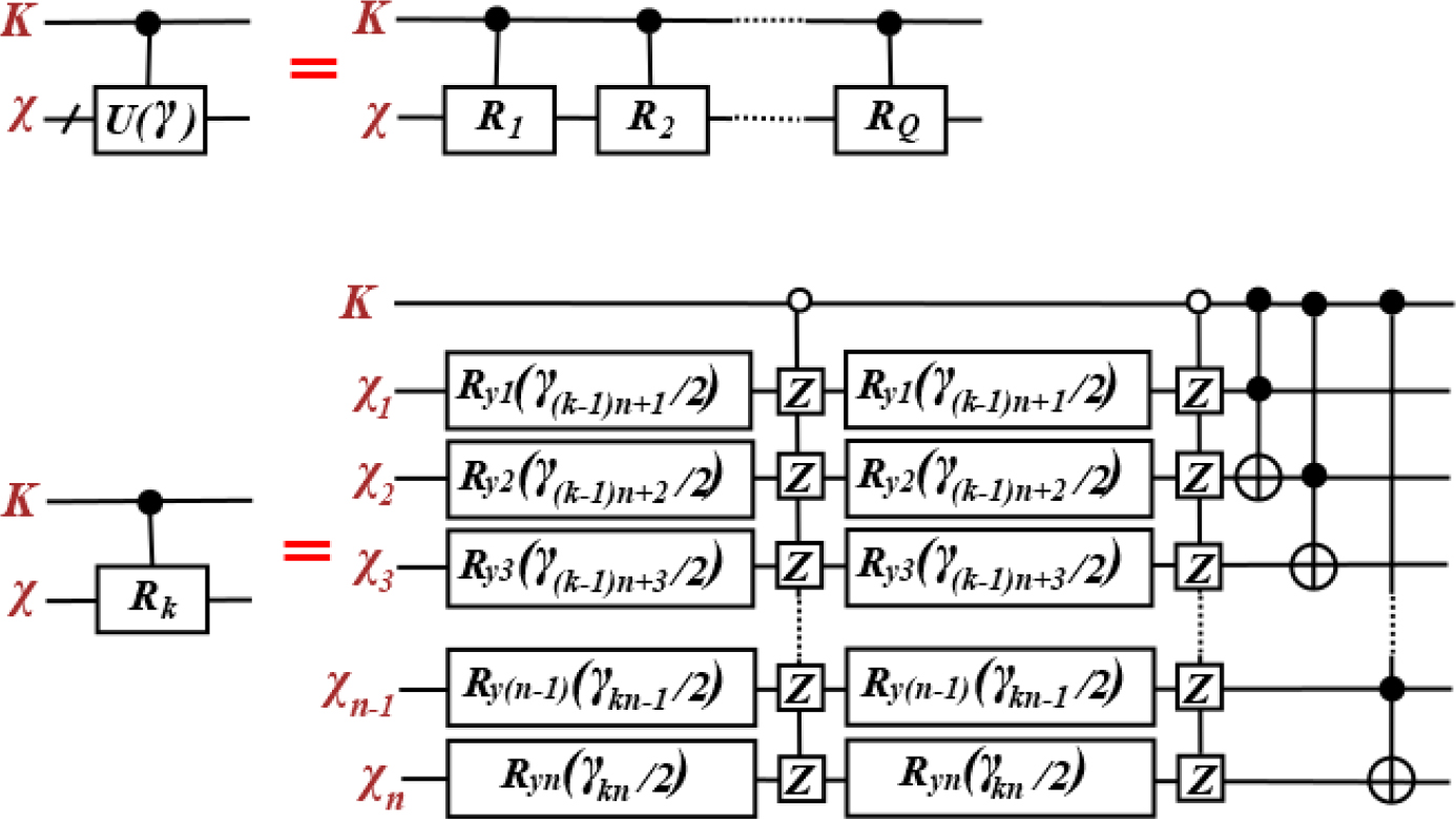
Figure 3.
The circuit for the operators (and ). Here the set of parameters γ is either α (for ) or β (for ), Z ≡ σ(z).
2.4. Derivatives of Objective Function
The input data for the classical optimization algorithm include not only the value of the objective function at the given values of the parameters α and β, but also derivatives of the objective function with respect to these parameters. It can be shown [26] that the required derivatives can be obtained calculating the objective function at certain values of the parameters α and β using the algorithm presented in Section 2.2.
Let be the set of all parameters α and β: . Since all the parameters are introduced through the Ry-rotation, it is simple to calculate any-order derivative of L with respect to the parameters [26]. For instance, for the first- and second-order derivatives we have
Here means the set of parameters , in which is replaced with and is the set of parameters , in which is replaced with , i.e.,
In order to probabilistically find at fixed values of the parameters, we have to perform one set of runs of quantum algorithm, the number of runs Nr in this set is determined by the required precision ε of L: Nr ~ 1/ε. Similarly, to probabilistically find all the first derivatives , k = 1,…, 2nQ, at fixed values of the parameters, we have to perform 2nQ sets of runs (one set for each derivative). If the optimization algorithm requires also the second derivatives , k, m = 1,…, 2nQ, we have to perform sets of runs in addition to the above runs (we take into account that ). The higher order derivatives of the objective function can be treated similarly. In this way we supply the objective function along with all necessary derivatives of this function to the input of the classical optimization algorithm which calculates the successive values of the parameters .
2.5. Hybrid Algorithm for SVD: Brief Discussion
The variational algorithm for calculating the SVD is a hybrid one. It is described in Refs. [26,27] in details including examples of realization of the algorithm via Paddle Quantum [28] on the PaddlePaddle Deep Learning Platform [29,30]. The accuracy of the SVD obtained via the variational algorithm is estimated by comparing it with the original matrix. In [26], the authors give detailed analysis of variational quantum SVD (VQSVD) for the randomly generated 8 × 8 matrix M. The quality of VQSVD was characterized by the matrix distance ∥M – MSVD∥2, MSVD is given in (1), . It was shown that this distance reduces with an increase in the parameter Q. Several realizations of the unitary transformation U (see eq. (4)) where given and some applications of VQSVD (in particular, in Recommendation systems) were proposed. An alternative VQSVD was proposed in [27] with the principal novelty in encoding the elements of the matrix M into the quantum state of some system, at that the matrix elements must be ordered according to the certain scheme. The objective function was also different therein. The quality of VQSVD was characterized by the matrix distance using the Frobenius norm. In comparison with the VQSVD in [26], the modified algorithm demonstrates certain advantages.
The structure of the hybrid SVD algorithm is shown in Figure 4. We use the superscript [j] to label the jth iteration values of the parameters . The algorithm can be briefly described as follow. For some initial values of the parameters we calculate the values of the objective function and its derivatives with respect to the parameters using the quantum algorithm. Then we use the found values of the objective function and its derivatives as the input for the classical optimization algorithm (for instance, for the gradient maximization algorithm) to find the succeeding iterated values of the parameters . Next, we put them to the input of quantum algorithm, which calculates the objective function and its derivatives for the new values of the parameters and so on till we reach the required convergence criterion ε ≪ 1, i.e., till the following condition is satisfied: . The scheme for this algorithm is shown in Figure 4.

Figure 4.
The hybrid algorithm for calculating SVD. The matrices Û, D and are defined in terms of U(α*) and U(β*) according to (4), ΔL = |L[k+1] – L[k]|. For simplicity, we indicate only the function L and first derivatives ∂γL to be transferred from the output of the quantum algorithm to the input of the classical algorithm. However, the higher order derivatives might be required as well.
3. Conclusions
We present a new version of the quantum part of the variational SVD algorithm based on the matrix encoding approach, when the entries of the matrix M are encoded into the probability amplitudes of the superposition state of a quantum system, in our case, subsystems R, C. The one-qubit subsystem K is an auxiliary subsystem that controls set of unitary operations. Eventually, the resulting state |Ψout〉KB is the superposition state of this auxiliary system K multiplied by the excited state |1〉B of the ancilla B. This state is obtained as a result of controlled measurement of the ancilla which removes the problem of small success probability that unavoidably appears in the case of ordinary measurement of the ancilla state because of the Hadamard transformation used in this algorithm. At the moment, we cannot suggest a particular realization of the controlled measurement. However, this operator means the control of the classical operation (measurement of the qubit ) by the quantum state of another qubit which is the qubit B in our case, and there is no any particular reason to discard possibility of such control. This control would reflect the deep relation between the classical and quantum phenomena without strong border between them. The controlled measurement means that the measurement of will be performed if only the superposition state includes the excited qubit |1〉B. Otherwise, the quantum system remains unchanged. Thus, the realization of controlled measurement remains an open problem. It is quite possible that this concept requires some modification to be realizable.
To measure the value of the objective function we use the state |Ψout〉KB and, after the Hadamard and controlled Hadamard transformations, we find the probabilities of the states |i〉K|j〉B and then required objective function L(α, β). Since the result is probabilistic we have to run the algorithm many times to obtain the required precision for the objective function. However, this multiple running is a necessary part of any probabilistic algorithm. In a similar way we can calculate all derivatives of the objective function required for running the classical optimization algorithm. The depth of the whole quantum algorithm can be estimated as O(Qlog(N)/ε), it linearly depends on the number of runs Nr which, in turn, is inverse proportional to the precision ε required for the probabilistic measurement of the objective function. The space of the algorithm is O(log N). We also notice that the different type of the matrix encoding is used in [27] yielding certain privileges for that algorithm over the algorithm in [26].
Although our algorithm deals with square matrices, it can be applied to the rectangular matrices as well because the rectangular matrix can be written in a square form by adding appropriate number of zero rows or columns. We also have to note that SVD is also a key for constructing the inverse or pseudoinverse of the matrix [34] because the pseudoinverse matrix for any given matrix A having SVD, , can be written as .
The fact that matrix-encoding approach is applicable to the variational Quantum SVD algorithm confirms the wide applicability of this approach which has already been used in algorithms for matrix manipulations including addition, multiplication, determinant calculation, inverse matrix calculation and solving systems of linear equations [11–13,38].
Acknowledgments
The manuscript is supported by the National Natural Science Foundation of China (Grants No. 12031004, No. 12271474 and No. 61877054). The work was partially funded by a state task of Russian Fundamental Investigations (State Registration No. 124013000760-0).
Notes
[1] Contributed by Author Contributions
All authors contributed equally to this work. All authors have read and agreed to the published version of the manuscript.
[2] Conflicts of interest Conflicts of Interest
The authors claim that they do not have any Conflict of Interest.
[3] Data Availability Statement
All necessary data are included into the manuscript.