
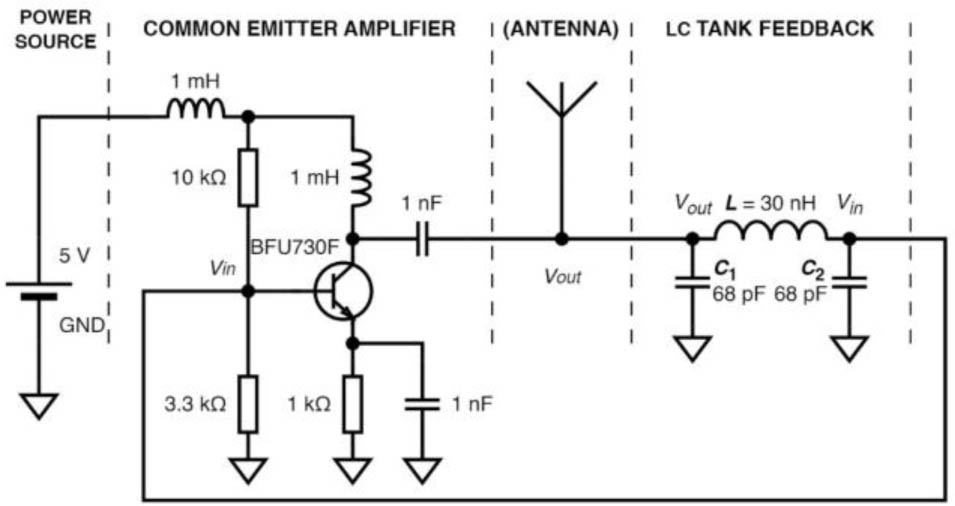
Fig. 1.
Circuit diagram of Colpitts oscillator with a common emitter [18].
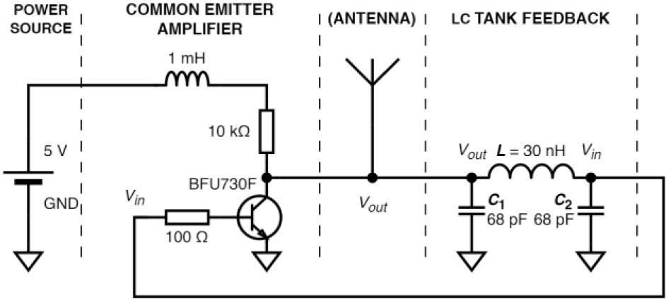
Fig. 2.
Simplified Colpitts oscillator circuit diagram [18].
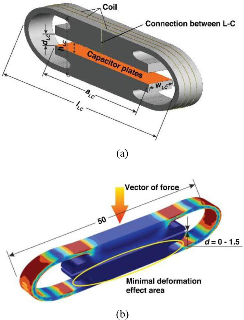
Fig. 3.
Visualization of the experimental transducer (compact compliant mechanical body with inductor and capacitor in parallel): (a) 3D model with dimensions; (b) deformation of the elastic element [17].
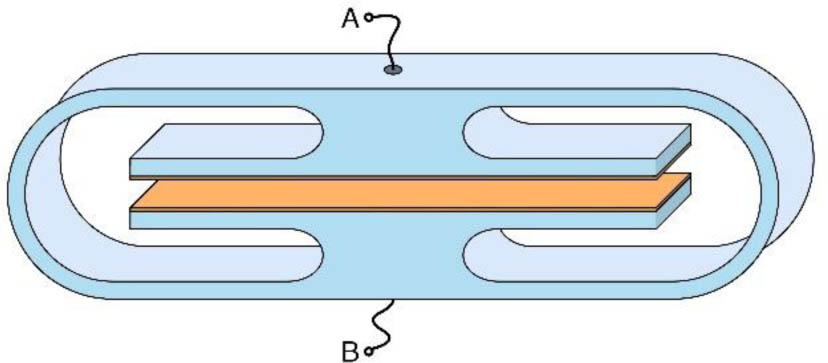
Fig. 4.
3D visualization of proposed CCCMB.
Table 1.
Parameters of the proposed CCCMB (see Fig. 5).
| Parameter | Value [mm] | Parameter | Value [mm] |
|---|---|---|---|
| L | 110.0 | H | 30.0 |
| L1 | 2.5 | H1 | 25.0 |
| L2 | 20.0 | H2 | 2.5 |
| L3 | 75.0 | H3 | 2.5 |
| R1 | 15.0 | H4 | 0.3 |
| R2 | 12.5 | W | 20.0 |
| R3 | 2.5 | G | 4.4 |
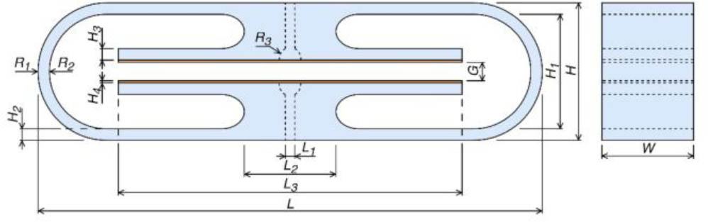
Fig. 5.
Geometry of the proposed capacitive compact compliant mechanical body.
Table 2.
Theoretical calculations of CCCMB capacity C1 and resulting oscillator frequency f at different plate distances G.
| G [mm] | C1 [pF] | f [MHz] |
|---|---|---|
| 4.00 | 3.32 | 516.31 |
| 3.00 | 4.43 | 450.60 |
| 2.00 | 6.64 | 373.50 |
| 1.00 | 13.29 | 275.60 |
| 0.50 | 26.58 | 210.21 |
| 0.20 | 66.45 | 158.51 |
| 0.10 | 132.88 | 137.01 |
Table 3.
Theoretical calculations of CCCMB capacity Cb, resulting capacity C′1, and resulting oscillator frequency f at different plate distances G.
| G [mm] | Cb [pF] | C′1 [pF] | f [MHz] |
|---|---|---|---|
| 4.00 | 3.32 | 71.32 | 155.74 |
| 3.00 | 4.43 | 72.43 | 155.16 |
| 2.00 | 6.64 | 74.64 | 154.04 |
| 1.00 | 13.29 | 81.29 | 151.01 |
| 0.50 | 26.58 | 94.58 | 146.10 |
| 0.20 | 66.45 | 134.44 | 136.74 |
| 0.10 | 132.88 | 200.88 | 128.92 |
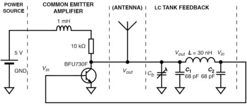
Fig. 6.
Manufactured sensor circuit diagram.
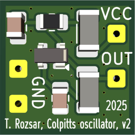
Fig. 7.
3D visualization of the fabricated sensor mounted on a PCB.
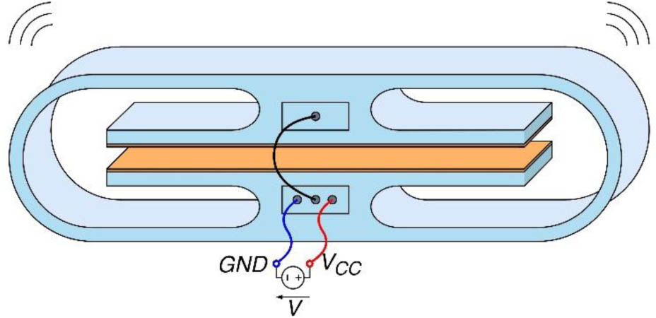
Fig. 8.
3D visualization of a sensor of mechanical quantity.
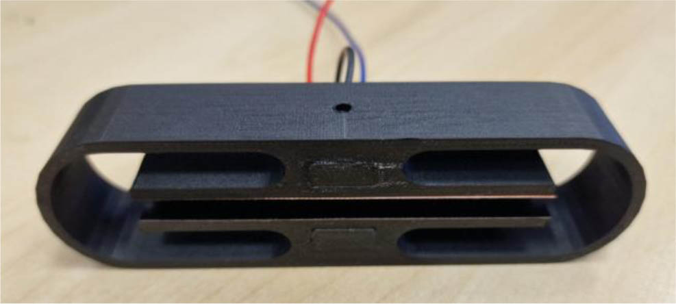
Fig. 9.
Manufactured sensor of mechanical quantity from the PET-G body.
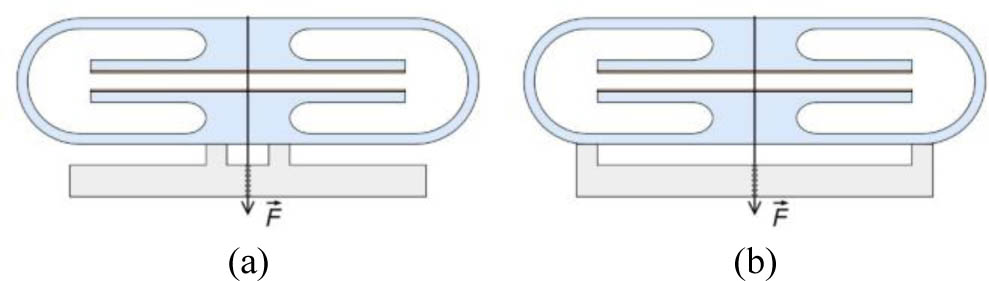
Fig. 10.
Measurement: (a) center-supported; (b) edge-supported.
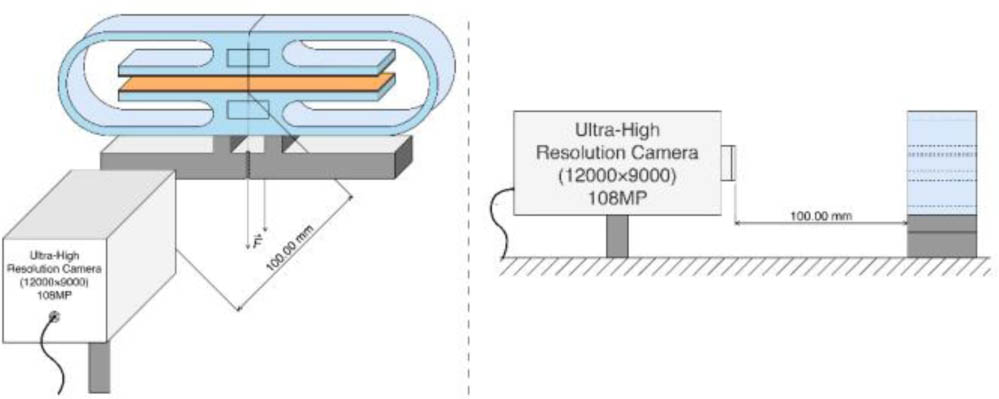
Fig. 11.
Visualization of optical measurement of electrode distance.
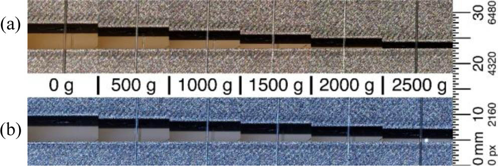
Fig. 12.
Optical measurement of the dependence of the distance between plates G on the magnitude of the force acting on CCCMB (without conductive plates): (a) center-supported measurement; (b) edge-supported measurement.
Table 4.
Measured distances G′ and G″ depending on the magnitude of the acting force.
| m [g] | G′ [px] | G′ [mm] | G″ [px] | G″ [mm] |
|---|---|---|---|---|
| 0 | 1089 | 4.44 | 1089 | 4.44 |
| 500 | 979 | 3.93 | 918 | 3.65 |
| 1000 | 874 | 3.45 | 753 | 2.89 |
| 1500 | 768 | 2.96 | 588 | 2.12 |
| 2000 | 660 | 2.46 | 430 | 1.39 |
| 2500 | 552 | 1.96 | 267 | 0.64 |
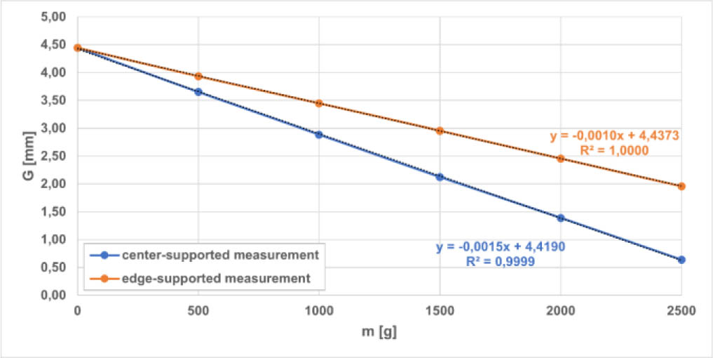
Fig. 13.
Dependence of the distance between the conductive plates G on the magnitude of the acting force (weight) m.
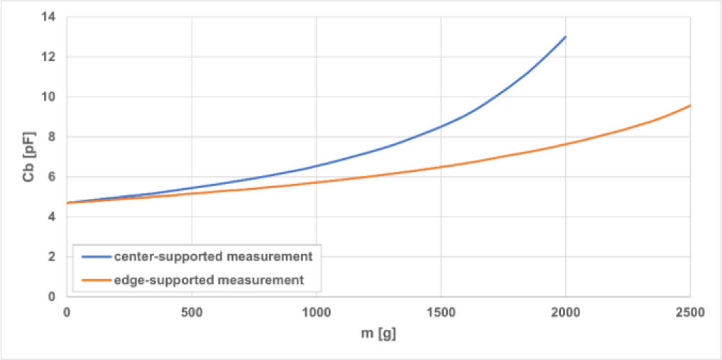
Fig. 14.
Measured dependence of the CCCMB capacity Cb on the magnitude of the acting force (weight) m.
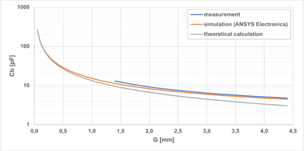
Fig. 15.
Measured, simulated, and theoretically calculated dependence of CCCMB distance between the conductive plates G (center-supported measurement).

Fig. 16.
Measured, simulated, and theoretically calculated dependence of CCCMB capacity Cb on the magnitude of the acting force (weight) m (center-supported measurement).
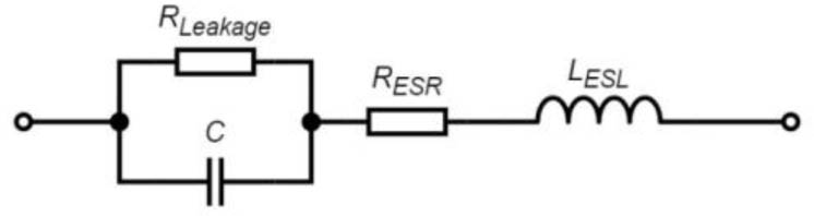
Fig. 17.
Equivalent circuit of real capacitor [19].
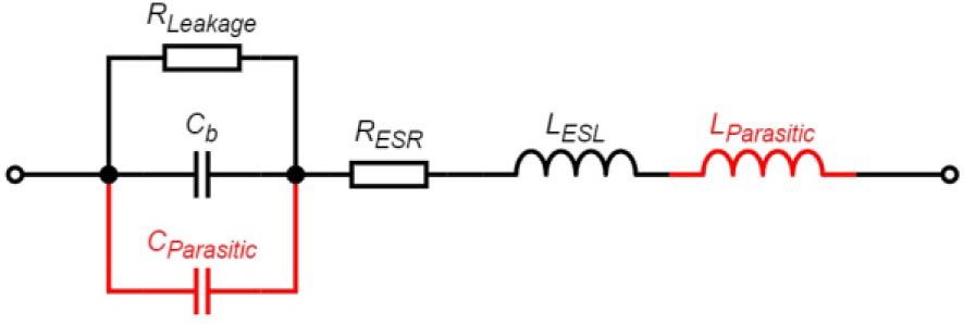
Fig. 18.
Extended and supplemented equivalent circuit of manufactured CCCMB as capacitor with additional parasites.
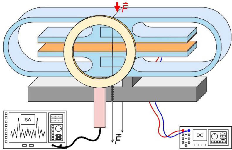
Fig. 19.
3D visualization of the measurement of frequency dependence on the magnitude of the acting force (center-supported measurement).
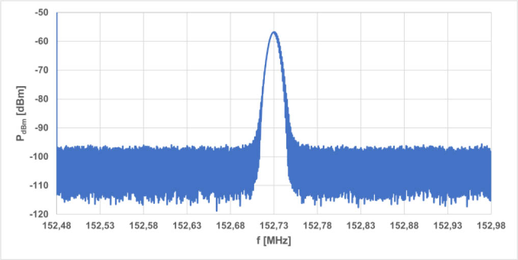
Fig. 20.
Measured frequency spectrum of the sensor in an unloaded state.
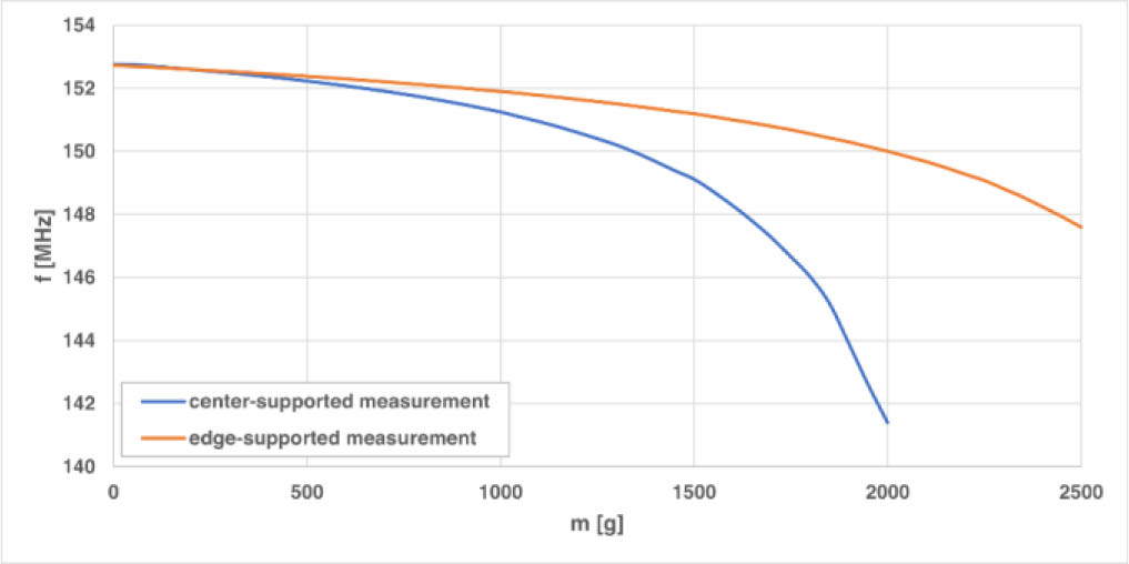
Fig. 21.
Measured dependencies of frequency on force magnitude for center-supported and edge-supported measurements.
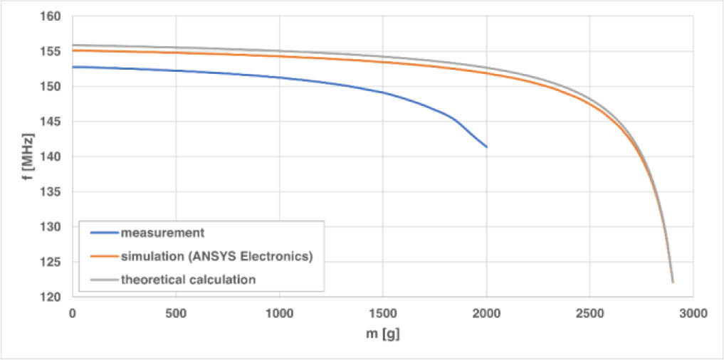
Fig. 22.
Measured, simulated, and theoretically calculated dependence of sensor frequency f on the magnitude of the acting force (weight) m (center-supported measurement).