
1. Introduction
Mechanical quantities include basic quantities such as force, mass, acceleration, pressure, and velocity, which describe the state and motion of objects. Thanks to their wide range of applications in transportation, healthcare, smart homes, and security systems, the development of sensors capable of detecting various mechanical stimuli – such as pressure, shear, bending, tension, or deflection – is a very attractive and rapidly developing field that supports overall technological progress [1].
Seventy years ago, in 1954, a fundamental discovery was made in the field of mechanical sensors – the discovery of the piezoresistive effect. This enabled the development of semiconductor strain gauges with significantly higher sensitivity than previous metal strain gauges, and later laid the foundations for the first micromechanically prepared silicon devices and subsequently MEMS technology [2].
Sensors of mechanical quantities based on the radio frequency (RF) principle are a class of passive sensors in which a mechanical quantity manifests as a shift in resonant frequency. The sensor is based on an RF resonator with its own resonant frequency, such as an LC circuit, a microwave structure, a chipless radio frequency identification (RFID) element, or an mm-wave resonator [3]. Mechanical deformation, depending on the applied quantity, alters its electromagnetic parameters.
Sensors can be classified into several types based on how mechanical quantities are converted into electrical signals, and more generally, according to their operating principle:
capacitive [4];
piezoelectric [4];
or, e.g., microelectromechanical system (MEMS) sensors with various transduction principles. [4]
One option is a passive sensor based on a plate capacitor, whose capacity (electrical quantity) depends on the distance between the electrodes (mechanical quantity). When force or pressure is applied to the sensor, it causes a change in the distance between the electrodes (resulting in a capacitive variation), a deformation or dimensional change of the resonator, or a modification of the effective permittivity.
The advantages of passive RF sensors of this type include:
High-temperature tolerance due to the absence of active electronics, enabling operation in harsh environments up to several hundred degrees Celsius [6].
Operation in extreme temperature environments (up to 500–850 °C when ceramic materials are used) [7], [8].
Wireless operation over distances ranging from several centimeters to tens of centimeters [8], [9].
Simple integration into composites, packaging, implants, and robotic systems [1].
In contrast, active RF sensors offer different advantages:
Higher operating frequency range and increased output power enabled by power amplification.
Higher sensitivity and accuracy in certain configurations [10].
High sensitivity in RF-based pressure sensing has been demonstrated in several published works. Representative examples of passive devices include substrate integrated waveguide (SIW) microwave pressure sensors based on complementary split ring resonators (CSRRs) that have been specifically designed for extreme temperature applications. The use of a CSRR is motivated by its strong electromagnetic field confinement and high sensitivity to variations in the effective permittivity and geometry of the surrounding structure. The CSRR configuration enhances the interaction between the resonant field and mechanical deformation induced by pressure, thereby improving sensitivity and enabling measurable frequency shifts. Additionally, its planar and integrable structure makes it suitable for SIW implementations and for operation under high-temperature and mechanically stressed conditions.
These sensors operate reliably over a wide temperature range, with sensitivity ranging from 139.77 kHz/kPa at 25 °C to 191.97 kHz/kPa at high temperatures, demonstrating the advantage of the CSRR configuration in terms of dielectric dissipation and thermal stress handling [7]. Additional examples include alumina-based passive RF sensors capable of operating up to 850 °C with a measurement distance of 5.5 cm [8], as well as implantable LC pressure sensors that maintain stable operation up to 800 °C, exhibiting low error and high linearity [11].
In addition to resonator-based microwave sensors, chipless RFID pressure sensors form an important class due to their passive operation, low cost, and adaptability via additive manufacturing (AM). These sensors exploit structural or dielectric variations to modulate resonance, enabling optimization of sensing range, sensitivity, and resolution for specific applications [12]. Advanced designs further integrate material properties with controlled frequency shifts, allowing tailored sensor responses [13]. This concept is extended by millimeter-wave (mm-wave) chipless sensors, which achieve reliable measurements beyond 5 cm without external antennas, operating in the Ka-band [9].
Another category comprises highly precise piezoresistive MEMS sensors for catheter-based applications, achieving a sensitivity of 108 Ω/N and a linearity of 99.5 %, enabling accurate real-time monitoring of contact forces during cardiac ablation procedures [14].
Since these are passive RF sensors, the frequency can often be read using an antenna and a network analyzer without the need for power on the sensor side, wireless, and often over longer distances (cm to tens of cm) [15]. However, there are also active versions of sensors that (unlike passive ones) require power, but their frequency can be read from much greater distances than in the case of passive sensors.”
Building on previous research [16], [17] on the development of passive sensors, this work focuses on the development of active sensors, in which the mechanical quantity is represented by the force applied to the sensor.
In such cases, an RF resonator is directly connected to the sensor circuits, whose resonant frequency is "transmitted into the environment". Finally, the obtained frequency is converted from the measured resonance frequency value back to a mechanical quantity, more precisely, its magnitude, according to the known transfer characteristic of the sensor.
In the previous article [18], the basic component of the sensor, namely the Colpitts oscillator, and its optimization for this purpose were addressed. The goal of this research was to obtain a circuit that minimizes the number of components (from the original 11 to 7) and, by extension, the dimensions of the oscillator itself. According to [18], the current consumption was successfully reduced from several milliamperes to just over 430 μA, while maintaining correct operation and stability of the oscillator. This type of oscillator / circuit is capable of addressing the current problem.
2. Subject & methods
The Colpitts oscillator is a type of oscillator that uses aparallel combination of inductance (coil or choke) and capacitance (capacitor) to generate oscillations. This oscillator is one of the most common types of oscillators in analog electronic circuits and is often used in various applications such as RF circuits, signal generators, and others. It is because its topology naturally provides better stability, a higher usable frequency, and easier implementation than many other LC oscillator types. The advantages come mainly from how feedback is taken and how parasitics interact with the tank circuit. The transistor's stray capacitances can be absorbed into the capacitive divider, while Hartley or Armstrong oscillators are more sensitive to stray capacitances. Also, these parasitics may shift the Hartley or Armstrong oscillators' oscillation frequency more unpredictably.
A. Characteristics of the Colpitts oscillator
The Colpitts oscillator has several key characteristics:
It uses capacitive feedback to generate oscillations. The basic idea is that the capacitive voltage divider creates the correct phase of the feedback signal needed to support oscillations.
The Colpitts oscillator uses a combination of two capacitors (C1, C2) and one inductor (L). These capacitors form a voltage divider and provide the correct phase shift. The parallel-connected capacitors C1 and C2 together form Ceq, whose size is given as
or, after adjustment,The total phase shift between the output and feedback signals is 180°, which is a condition for maintaining oscillations.
The frequency of oscillations depends on the values of capacitance and inductance in the circuit. The basic formula for the frequency of a Colpitts oscillator is
where f is the oscillation frequency, L is the coil inductance, and Ceq is the equivalent capacitance. Substituting (2) into (3) gives The frequency of oscillations can therefore be changed either by changing the inductance (L) or by changing (at least) one capacitance (C1 and / or C2).
The above applies to both the general oscillator connection and our optimized connection.
The oscillators shown in the figures above (Fig. 1 and Fig. 2) were designed for a frequency of approximately 158 MHz, which is also used in this article. The frequency was selected based on previous research [16].
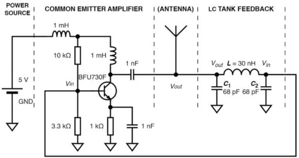
Fig. 1.
Circuit diagram of Colpitts oscillator with a common emitter [18].
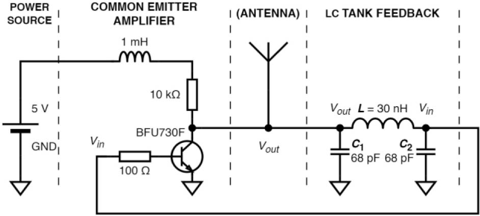
Fig. 2.
Simplified Colpitts oscillator circuit diagram [18].
The operating frequency of 158 MHz is not arbitrary, but results from the physical and electrical constraints of the proposed system. The geometry of the sensing element determines the effective electrode area and, consequently, the capacitance value. To achieve a reasonable quality factor Q of the resonant circuit, this capacitance must be paired with an inductance. Considering the resulting capacitance, the achievable inductor parameters, and the practical operating range and performance of the VCO, the suitable frequency range was found to be approximately 120–180 MHz. The selected frequency of 158 MHz, therefore, represents an optimal compromise within this range rather than a strictly fixed or unique value.
B. Oscillator frequency tunability
A possible way to tune the oscillator frequency is by varying the inductance L, which is given by
where N is the number of turns, μ is the permeability of the material, A is the coil cross-sectional area, and l is the coil length. In principle, L can be influenced by modifying the coil geometry, the number of turns, or the magnetic properties of the core material.However, changing the dielectric is not feasible in this application, as it cannot be reliably controlled as a function of the applied mechanical force. This option is therefore excluded. Moreover, maintaining a consistent coil geometry under mechanical loading is not possible, as deformation would cause variations in inductance. Consequently, the oscillator would exhibit different resonant frequencies for the same applied force, which prevents reliable force estimation from frequency measurements. These limitations effectively rule out inductance-based frequency tuning.
Given these constraints, attention shifts toward more stable frequency control mechanisms. In particular, variations in capacitance of the mechanical structure provide a more reliable solution. A compact compliant mechanical body (CCMB) is therefore employed, in which two conductive plates form a parallel-plate capacitor. The plates move relative to each other under applied load and are separated by an insulating material (dielectric ɛ).
where ɛ0 is the permittivity of vacuum (ɛ0 = 8.854·10−12 F/m), ɛr is the relative permittivity of the dielectric.In this case, an air dielectric is considered, with its permittivity ɛr ≈ 1.00054. The capacitance of such a capacitor is then given by the relationship
where A is the mutual area of the conductive plates and d is the distance between the conductive plates.Under these conditions, changing the dielectric is regarded as beyond the available capabilities. However, there are two options for changing the capacitance. One solution is to change the mutual area of the electrodes by shifting them in the plane of the plates while maintaining the same distance between the plates.
This option is suitable for measuring a normal force acting on the sensor, i.e., a force perpendicular to the plane of the capacitor plates.
Between the two approaches considered for capacitance variation, the most suitable solution is to change the distance d between the conductive plates (see (7)), while maintaining their mutual overlap area. However, this design is challenging because the parallelism of the plates must be maintained regardless of the applied force.
However, if the change in the distance between the plates is not uniform across the entire area, the capacitance will still change. In this case, an additional effect arises from the relative inclination of one plate with respect to the other. As a result, the effective overlapping area between the plates is also modified, which further influences the capacitance. Fortunately, however, we have solved this problem.
C. Compact compliant mechanical body
Harťanský et al. [17] have successfully developed and tested the shape of a compact compliant mechanical body, in which the application of force changes the distance between the electrodes while maintaining their mutual parallelism and the size of their mutual surfaces (Fig. 3). This shape of body (and consequently of the capacitor) was chosen for use.
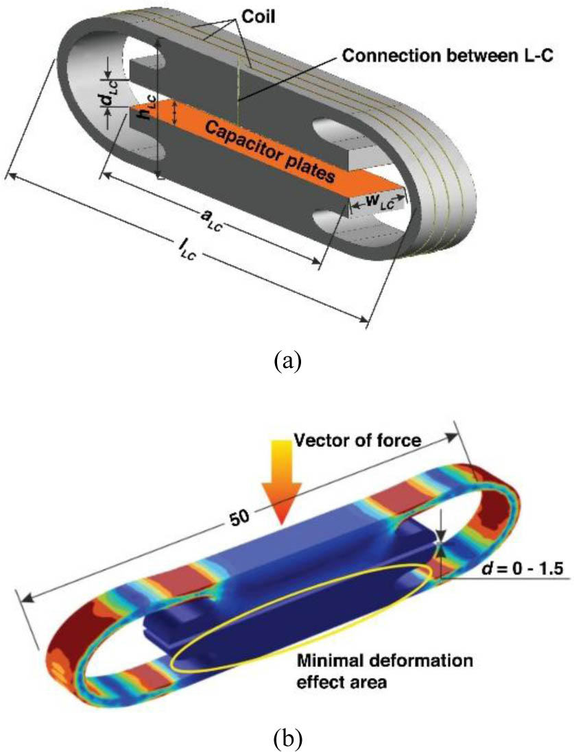
Fig. 3.
Visualization of the experimental transducer (compact compliant mechanical body with inductor and capacitor in parallel): (a) 3D model with dimensions; (b) deformation of the elastic element [17].
In the case of [17], a parallel LC element was used. If the oscillator feedback were replaced with such a body, operation would still be possible; however, it would no longer constitute a Colpitts oscillator, and, at the same time, as only one capacitor representing Ceq in (3) would be present in the feedback, a large change in frequency could be obtained from a small change in force.
However, such a strong frequency sensitivity may lead to operation over a very wide frequency range. In this case, the oscillation frequency could fall within bands commonly occupied by other signals or external sources, potentially causing ambiguity in identifying the sensor-generated signal due to possible overlap with unwanted interference. Consequently, the sensor response may become difficult to distinguish from other spectral components, leading to a loss of usable measurement information.
A Colpitts oscillator employs a capacitive voltage divider formed by two series-connected capacitors in the feedback network, as already mentioned. To stabilize the effective capacitance and the resulting oscillation frequency, an additional fixed capacitor is connected in parallel with one of the divider capacitors. This ensures that only the CCMB sensing capacitance varies with applied force, while the parallel capacitor provides a stable reference and prevents unwanted frequency drift.
D. Capacitive compact compliant mechanical body
In Fig. 4, a 3D visualization of the proposed capacitive compact compliant mechanical body (CCCMB) is presented, with the coil L replaced by a fixed external inductance as a separate component outside the CCCMB.
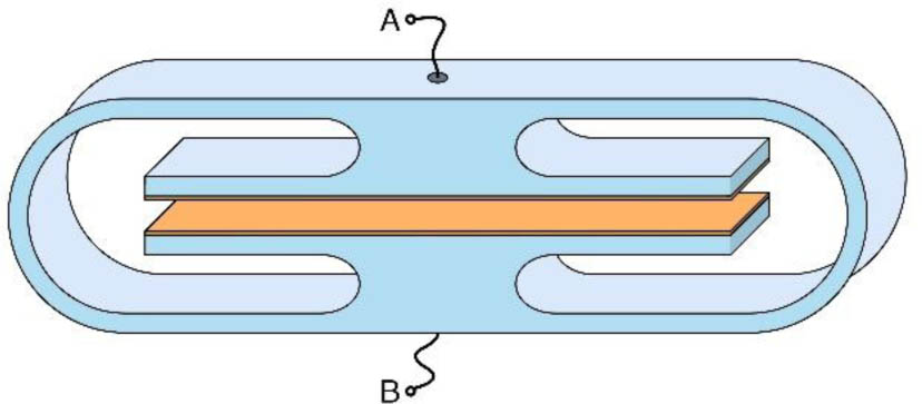
Fig. 4.
3D visualization of proposed CCCMB.
To ensure measurement results correlate as closely as possible with simulation or calculations results, conductors are routed to the top and bottom of the prototype to reduce their parasitic capacitance. The dimensions of the final CCCMB are shown in Table 1, as shown in Fig. 5.
Table 1.
Parameters of the proposed CCCMB (see Fig. 5).
| Parameter | Value [mm] | Parameter | Value [mm] |
|---|---|---|---|
| L | 110.0 | H | 30.0 |
| L1 | 2.5 | H1 | 25.0 |
| L2 | 20.0 | H2 | 2.5 |
| L3 | 75.0 | H3 | 2.5 |
| R1 | 15.0 | H4 | 0.3 |
| R2 | 12.5 | W | 20.0 |
| R3 | 2.5 | G | 4.4 |
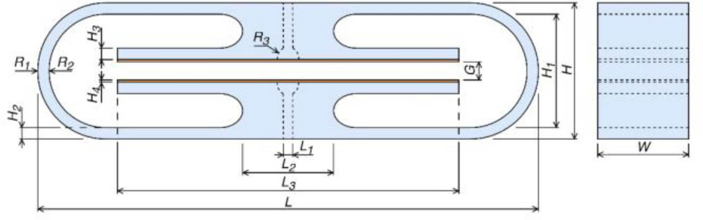
Fig. 5.
Geometry of the proposed capacitive compact compliant mechanical body.
In the case of an unloaded body, i.e., when the CCCMB is in its original state, its capacity using Fig. 5, Table 1, (6) and (7) is equal to
In an unloaded state, CCCMB has only about 3 pF. When a force acts on the CCCMB, the conductive plates of the capacitor move closer together, increasing the capacitance. When large weights act on the flexible CCCMB, these plates move so close together that the capacitance increases rapidly. For clarity, Table 2 shows a few theoretically calculated capacitances of the proposed flexible CCCMB and the resulting oscillator frequency depending on the distance (gap) between the plates G. (We assume that CCCMB replaces C1, C2 = 68 pF, L = 30 nH.) Then, according to (4), the following applies in Table 2.
Table 2.
Theoretical calculations of CCCMB capacity C1 and resulting oscillator frequency f at different plate distances G.
| G [mm] | C1 [pF] | f [MHz] |
|---|---|---|
| 4.00 | 3.32 | 516.31 |
| 3.00 | 4.43 | 450.60 |
| 2.00 | 6.64 | 373.50 |
| 1.00 | 13.29 | 275.60 |
| 0.50 | 26.58 | 210.21 |
| 0.20 | 66.45 | 158.51 |
| 0.10 | 132.88 | 137.01 |
Although theoretical calculations have given us a very wide frequency range for the oscillator, in reality, there may be significant problems with the design, implementation, and, above all, the stability of the oscillator across its entire operating range. In some applications, this can be an advantage, in others not. The advantage of a wide range is seen when force needs to be measured with very high accuracy. Another major advantage of the sensor's high sensitivity and wide frequency range is that stiffer and more brittle materials can be used for CCMB.
Stiff materials, such as ceramics, enable significant miniaturization of the sensing structure while preserving elastic behavior under load. As a result, even small mechanical displacements can induce relatively large changes in capacitance, since capacitance is strongly dependent on the electrode spacing.
However, stiffer and more brittle materials cannot be compressed or bent to the same extent as flexible polymers such as PET-G, which can be easily used to fabricate a CCMB structure with sufficient precision via 3D printing. Consequently, in ceramic-based designs, it is not possible to achieve the same range of electrode displacement with identical geometrical dimensions, limiting the effective utilization of the sensor's frequency range. On the other hand, their high stiffness enables substantial miniaturization of the sensing element. With a small initial electrode gap G (in the order of tens to hundreds of micrometers) in the unloaded state, even small applied forces produce measurable capacitance changes and, consequently, significant frequency shifts. In particular, by designing an inherently small initial separation between the capacitor plates in the ceramic structure, a relatively small mechanical deformation can result in a large relative change in capacitance, thereby enabling good frequency tunability of the sensor.
In this case, where the sensor is being developed on a flexible CCCMB, it is important to achieve a compromise between accuracy and frequency range to maintain oscillator stability. If the CCCMB were used as one of the capacitors in the feedback capacitive divider, an uncontrollable change in oscillator frequency could result, preventing the designed oscillator from functioning at very high frequencies. Oscillator stability can, however, be guaranteed at approximately 158 MHz, the frequency at which it was previously tested [18]. Fast measurement and high resolution of the measured force can still be achieved.
It is therefore suggested that the original oscillator circuit with elements C1, C2, and L in the feedback loop be retained, and that the capacitance of the CCCMB be designated as Cb and connected in parallel to capacitor C1, which is set to have the same value as capacitor C2, namely 68 pF.
According to the wiring diagram in Fig. 1 and Fig. 2, capacitor C1 is connected to the same node as the planned antenna for radiating at the oscillator frequency. The CCCMB can thus be used as an “antenna” to support transmission. Although the expected efficiency will be rather poor, it will still be nonzero. The radiation and efficiency of the “external” antenna were not the subject of the current research. The resulting capacity C'1 of the parallel connection of C1 and Cb will be
where C1 is the capacitance of capacitor No. 1 in the feedback circuit, and Cb is the capacitance of CCCMB in the feedback circuit.Then, the frequency at the same CCCMB load, and consequently the distance between the plates using (4), is calculated by substituting the new resulting C'1 for C1, which will be equal to
The oscillator frequencies obtained in this way for the same distances between CCCMB plates are summarized in Table 2.
As a result, for the distances considered, the original frequency range from 130 MHz to approximately 520 MHz was adjusted to a range from 130 MHz to approximately 160 MHz, i.e., to less than one-thirteenth (see Table 3).
Table 3.
Theoretical calculations of CCCMB capacity Cb, resulting capacity C′1, and resulting oscillator frequency f at different plate distances G.
| G [mm] | Cb [pF] | C′1 [pF] | f [MHz] |
|---|---|---|---|
| 4.00 | 3.32 | 71.32 | 155.74 |
| 3.00 | 4.43 | 72.43 | 155.16 |
| 2.00 | 6.64 | 74.64 | 154.04 |
| 1.00 | 13.29 | 81.29 | 151.01 |
| 0.50 | 26.58 | 94.58 | 146.10 |
| 0.20 | 66.45 | 134.44 | 136.74 |
| 0.10 | 132.88 | 200.88 | 128.92 |
The theoretical results met the requirements, thereby enabling progression to the practical part of the study. The circuits were built and tuned accordingly.
E. Development and optimization of the sensor
The design objective was to minimize the power consumption required to sustain oscillations. During feedback network optimization, different resistance values were evaluated to reduce overall power losses while maintaining stable oscillation conditions. The best performance was achieved when the resistance was effectively reduced to 0 Ω, indicating that no additional series resistance was necessary in the feedback path. Consequently, the original 100 Ω resistor (Fig. 2) was removed. This modification not only reduced the power consumption of the oscillator but also reduced the total number of components in the circuit, further simplifying the overall design. By removing the resistor and adding parallel capacitance Cb to the feedback, the number of components in the entire sensor did not change from the original oscillator. However, the result was a slight increase in the supply voltage and, consequently, in the current consumption. The supply voltage for stable sensor operation is Vcc = 1.2 V, with a current consumption of approximately 1 mA. The final oscillator circuit diagram is shown in Fig. 6.
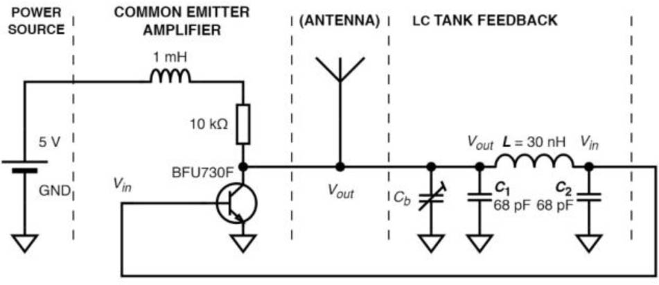
Fig. 6.
Manufactured sensor circuit diagram.
The current dimensions of the manufactured printed circuit board (PCB) are 12 mm × 12 mm (Fig. 7). This size allows us to integrate the circuits into the CCCMB, for which we have created slots.
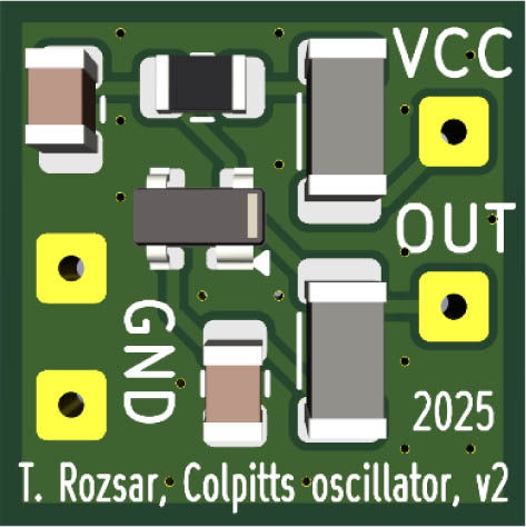
Fig. 7.
3D visualization of the fabricated sensor mounted on a PCB.
The slots (Fig. 8) are on both the top and bottom of the CCCMB to ensure the best possible distribution and application of weights. All circuits will be mounted on the bottom side, with the top side remaining unoccupied for now. Plugs for the slots have been manufactured and mounted, from which the necessary outputs are provided: the circuit power supply and a cable connecting the second CCCMB conductive plate to the circuits (Fig. 9). Next, simulations and measurements were carried out.
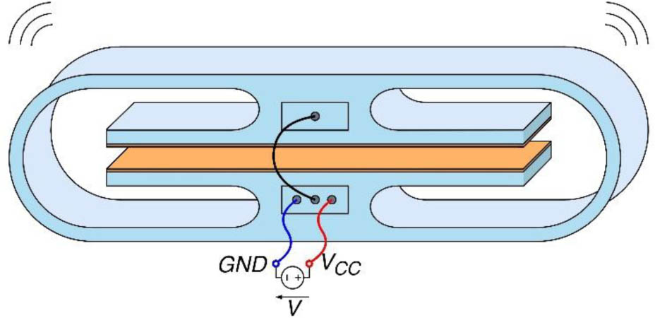
Fig. 8.
3D visualization of a sensor of mechanical quantity.
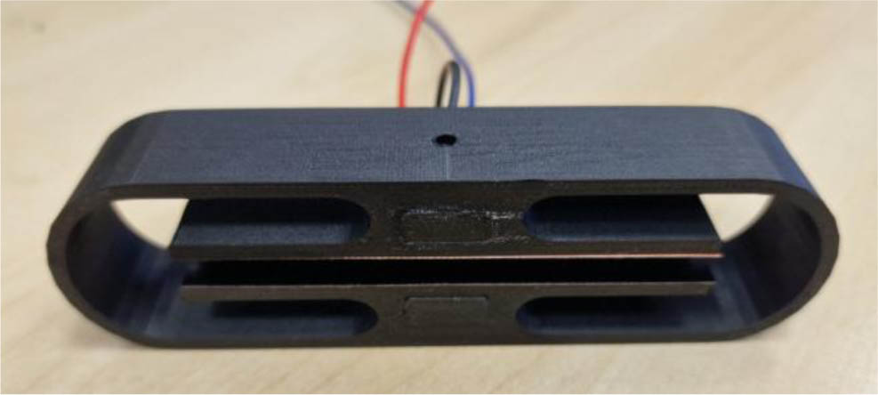
Fig. 9.
Manufactured sensor of mechanical quantity from the PET-G body.
3. Results
Although the stiffness of the body can, in principle, be estimated from known material properties, geometry, and dimensions, such an approach may not fully capture the real behavior of the structure, including manufacturing tolerances and boundary conditions. Therefore, to accurately reflect the actual mechanical response of the sensor body, its effective stiffness was experimentally determined.
At this point, it should be mentioned that the conductive plates were glued to the CCCMB. The imperfection of 3D printing and the layer of adhesive between the plates and the PET-G material caused a change in the distance between the conductive plates. The actual distance between the conductive plates of the manufactured and unloaded CCCMB is 4.40 mm.
The measurement procedure was repeated 10 times, always starting from the unloaded state up to the maximum applied load. The observed deviations were on the order of a few percent (less than 5 %) and were mainly due to minor inaccuracies in positioning the nylon thread and in applying the load exactly at the center of the sensor's top surface. The presented results correspond to the full measurement course obtained from a single complete measurement cycle. In addition, minor deviations may also arise from the elastic properties of the CCCMB structure itself, as slight viscoelastic effects and small mechanical relaxation can influence the repeatability of the response under identical loading conditions.
The conductive plates were attached to the 3D-printed PET-G structure using liquid adhesive, which may introduce small tolerances in the final capacitor geometry. In particular, the adhesive layer can slightly affect the nominal gap between the plates, and during manual assembly, the plates may be displaced by small offsets. As a result, perfect parallelism of the plates cannot be fully guaranteed, which may lead to minor variations in the effective overlapping area and, consequently, in the measured capacitance. These manufacturing and assembly tolerances may also contribute to the observed differences between the simulated and measured electrical parameters of the sensor.
If a mechanical quantity – force – is to be measured using the sensor, either a force of known magnitude and direction relative to the sensor can be applied, or a known weight via gravitational force can be applied, in which case the sensor must be positioned perpendicular to the direction of the gravitational force, i.e., in a horizontal plane. In the second case, the basic relationship (11) is used to convert between gravitational force and weight.
where F is the gravitational force, m is the weight, and g is the gravitational acceleration (g ≈ 9.81 m/s2).To simplify the measurements, they are performed using the second method; i.e., from this point onward, when the magnitude of the acting force is mentioned, it refers to the gravitational force F caused by the weight m acting perpendicular to the top of the sensor. Measurements were carried out for two cases:
The CCCMB was placed on a base made of the same material with a center-supported case at its center, as shown in Fig. 10(a), allowing the body to bend on both sides, up and down. Although the base had two support points to keep the CCCMB stable, their location was still within the zone where the deformation effect, according to [17], was minimal.
The CCCMB was placed on a base made of the same material, with two load points located at the edges of the CCMB (see Fig. 10(b)), allowing the body to bend on both sides, but in this case only upwards. The deflection on the lower side was greatly limited.
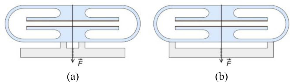
Fig. 10.
Measurement: (a) center-supported; (b) edge-supported.
The first measurement case will be referred to as the “center-supported measurement” and the second as the “edge-supported measurement.”
Below, in Table 4, the measured dependence of the distance between the conductive plates on the applied force for both measurement cases is presented.
As these were very small changes that could not be measured under the given conditions, a digital measurement method was employed, in which high-resolution photographs were evaluated. For each measurement step, a picture was taken, and the distance was determined using pixels. A visualization of the measurement of the distance between electrodes G is shown in Fig. 11.
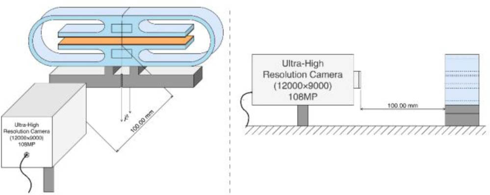
Fig. 11.
Visualization of optical measurement of electrode distance.
Finally, under the same conditions, a reference photograph was also taken with a micrometric gauge set at a distance of 10.00 mm. Photography conditions: photographing the CCCMB and micrometric gauge from the same distance, with the same resolution and camera settings. Using the reference photo, we determined the scale to be 10.00 mm = 2160 px.
Optical measurement of the distance between conductive plates G, depending on the magnitude of the force acting on CCMB, with a scale in pixels and millimeters, is shown in Fig. 12. The force was simulated using a calibration set of weights, which were suspended from thin nylon and acted on the center of the upper part of the CCCMB, pulling it down.
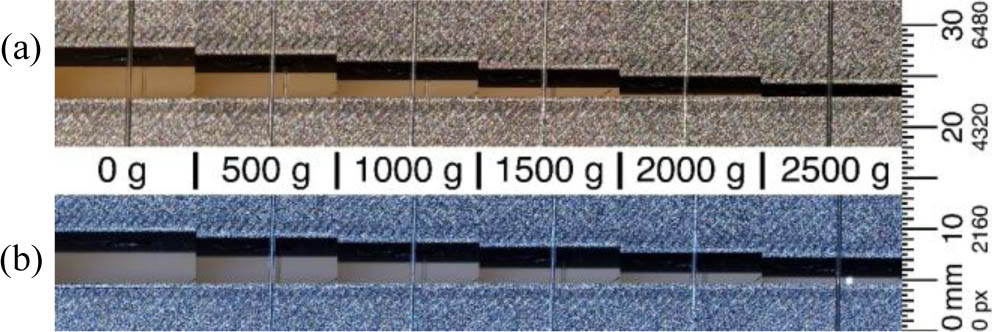
Fig. 12.
Optical measurement of the dependence of the distance between plates G on the magnitude of the force acting on CCCMB (without conductive plates): (a) center-supported measurement; (b) edge-supported measurement.
The dependence was measured without conductive plates to determine the behavior of CCCMB at a larger dispersion of distance G, even at a very small distance. The thickness of the conductive plates used is 0.30 mm. In total, twice the thickness of the plates, i.e., 0.60 mm, is subtracted from the measured distance.
The number of pixels obtained was converted to a distance in millimeters according to the scale. The distances obtained in pixels from photographs and converted to millimeters, depending on the magnitude of the acting force, are shown in Table 4. Distance G for center-supported measurement is marked as G′ and for edge-supported measurement as G″.
Table 4.
Measured distances G′ and G″ depending on the magnitude of the acting force.
| m [g] | G′ [px] | G′ [mm] | G″ [px] | G″ [mm] |
|---|---|---|---|---|
| 0 | 1089 | 4.44 | 1089 | 4.44 |
| 500 | 979 | 3.93 | 918 | 3.65 |
| 1000 | 874 | 3.45 | 753 | 2.89 |
| 1500 | 768 | 2.96 | 588 | 2.12 |
| 2000 | 660 | 2.46 | 430 | 1.39 |
| 2500 | 552 | 1.96 | 267 | 0.64 |
Below, a graphical representation of the dependence of the distance between the conductive plates on the magnitude of the applied force is also presented. Fig. 13 additionally shows linear fits of the dependence.
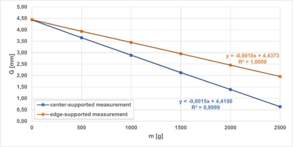
Fig. 13.
Dependence of the distance between the conductive plates G on the magnitude of the acting force (weight) m.
Since the transfer characteristic of the applied force at distance G of the CCCMB is already known, the first measurement of capacitance Cb was carried out.
The measurement was performed as shown in Fig. 10. The conductive plates were connected to the LCR meter via 20 cm wires. Fig. 14 shows the measured dependence of CCCMB capacitance Cb on the magnitude of the acting force for both center-supported and edge-supported measurements.
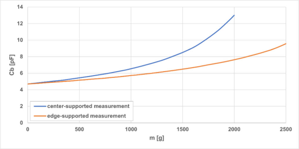
Fig. 14.
Measured dependence of the CCCMB capacity Cb on the magnitude of the acting force (weight) m.
Weight dependence was measured from the unloaded state of the CCCMB. The change in the size of the acting weight was achieved by gradually hanging weights (in 50 g increments) on a nylon cord. The weights used were from a calibration set. The body was gradually loaded up to 2 kg in the case of center-supported measurement and up to 2.5 kg in the second case (edge-supported measurement).
In the case of the center-supported configuration, comparable changes in the distance between the capacitive plates were observed at lower applied forces than in the edge-supported configuration. However, at higher loads (above 2 kg), the gap between the plates decreased significantly, resulting in a strong increase in capacitance. In this regime, even very small changes in the applied load resulted in a slow dynamic response, as the CCCMB deformation, the corresponding capacitance change, and, consequently, the oscillation frequency required several minutes to stabilize.
For this reason, the measurement in the center-supported configuration was limited to a load range of up to 2 kg, after which the electrical parameters stabilized within a few seconds after each load change, enabling reliable and repeatable measurements.
The thin nylon element used in the experimental setup serves solely as a mechanical means for load transmission. Its role is to transfer the applied force to the sensor rather than to act as a structural or sensing component.
From a mechanical standpoint, any elongation or flexural deformation of the nylon does not alter the magnitude of the applied load, which is defined by the external loading conditions (e.g., applied weights). Therefore, the sensor is subjected to the same force regardless of the nylon's deformation. Additionally, due to the relatively high stiffness of the sensor structure compared to the thin nylon element, the influence of nylon's mechanical properties on the measured sensor response is negligible. For this reason, the flexural and material properties of the nylon were not considered to significantly affect the measurement results.
By applying the measured dependence shown in Fig. 14 and the linear substitution obtained from the dependence in Fig. 13, the measured dependence of capacitance on the distance between the conductive plates G was obtained. This dependence was supplemented with dependencies obtained by theoretical calculation according to (8) and simulation in the ANSYS Electronics (Maxwell 3D) program. The electrostatic simulation and theoretical calculations were without parasitic parameters. A comparison of these dependencies is shown in Fig. 15.
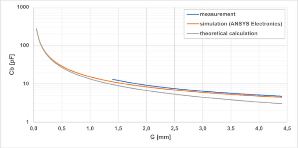
Fig. 15.
Measured, simulated, and theoretically calculated dependence of CCCMB distance between the conductive plates G (center-supported measurement).
By reapplying the same linear substitution, a dependency with greater informative value is obtained. This is the dependency of the CCCMB capacity Cb on the acting force (weight) m, which is shown in Fig. 16.
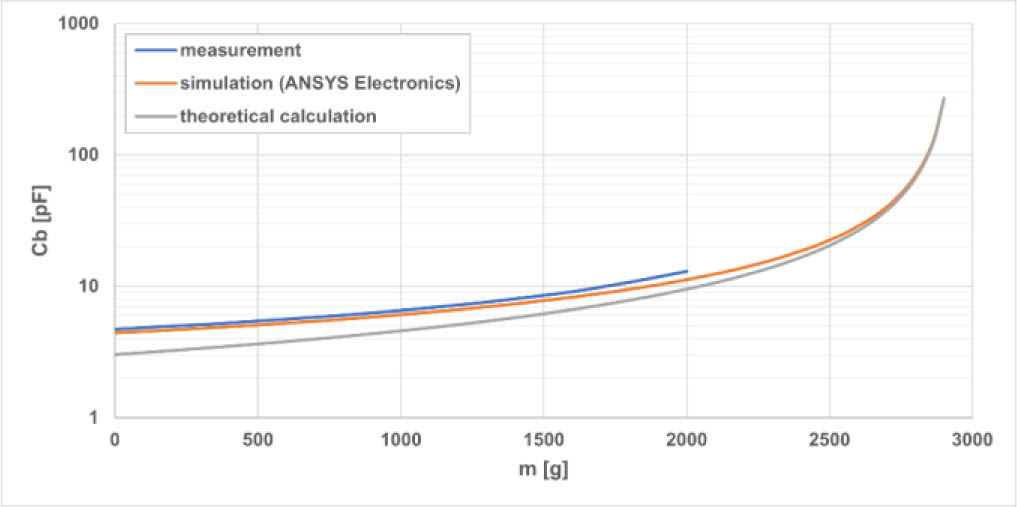
Fig. 16.
Measured, simulated, and theoretically calculated dependence of CCCMB capacity Cb on the magnitude of the acting force (weight) m (center-supported measurement).
Fig. 15 and Fig. 16 show only center-supported measurements. In the case of edge-supported measurement, the measured characteristics would be similar, but over a wider range of weights (see the force-distance transformation curve for conductive plates in Fig. 13). Slight deviations can be observed when comparing individual methods, whether theoretical or practical.
The equivalent circuit of the capacitor according to [12], shown in Fig. 17, is supplemented by the parasitic parallel capacitance of the capacitor conductors and the series inductance of the external connecting conductor CCCMB of unknown sizes (see Fig. 18).
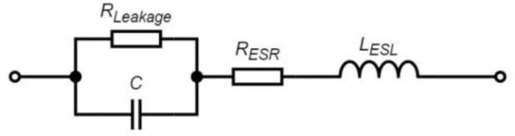
Fig. 17.
Equivalent circuit of real capacitor [19].
The above reasons are evident in all three methods – measurement, simulation, and theoretical calculation. However, they may not manifest themselves equally in all methods. For example, a very thin Teflon coating on the contact surfaces of the conductive plates, introduced during the manufacturing process, may introduce a deviation between simulation and analytical calculation compared to measurement, as this parasitic dielectric effect is inherently present.
The measured dependencies differ slightly, but these capacitance differences are very small compared to the simulation under the given working conditions. It can therefore be stated that the capacitance of CCCMB Cb behaves as expected.
C – real capacitance of the capacitor,
Cb – real capacitance of the CCCMB,
CParasitic – parasitic capacitance of conductors,
RERS – equivalent series resistance of leads and electrodes,
RLeakage – losses in the dielectric and insulation resistance,
LESL – equivalent series inductance of leads and electrodes,
LParasitic – inductance of the connecting conductor forming CCCMB.
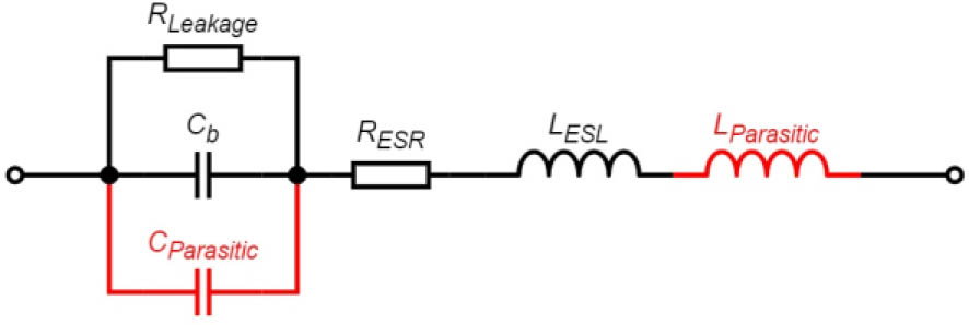
Fig. 18.
Extended and supplemented equivalent circuit of manufactured CCCMB as capacitor with additional parasites.
In the final step, the most important measurement was carried out. The frequency dependencies of the force sensor as a whole needed to be measured. The measurements were performed under the same conditions as before, except that the sensor was connected to a laboratory-stabilized source with a supply voltage of 1.2 V. A weight change step of 50 g was chosen. The application of force was again simulated using weights from the calibration set.
This time, a spectrum analyzer was used for the measurements, to which a near-field probe was connected via a 1 m cable using SMA connectors. The center of the probe was placed at the same height as the center of the air gap of the unloaded CCCMB. The probe was approximately 5 cm from the edge of the conductive plate. The CCCMB was oriented so that the cables protruding from the body were at the rear, minimizing their influence on the measurement. The distribution of the measurement setup is shown in Fig. 19. Measurements of the dependence of the oscillation frequency on the load were performed for both center-supported and edge-supported configurations. A graphical representation of both measurements is shown in the following figures.
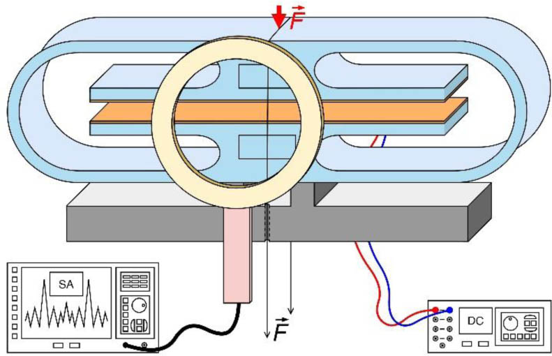
Fig. 19.
3D visualization of the measurement of frequency dependence on the magnitude of the acting force (center-supported measurement).
Using a spectrum analyzer, a preview of the narrow frequency spectrum was exported, showing the fundamental frequency of the oscillator at an unloaded body at 152.725 MHz with an amplitude of approximately −57 dBm (Fig. 20).
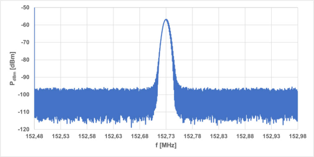
Fig. 20.
Measured frequency spectrum of the sensor in an unloaded state.
Although the amplitude is very small, it is necessary to consider it more deeply:
The constructed sensor does not contain an antenna, so the radiation is not “supported” externally in any way;
The device is powered by a low supply voltage with low current consumption;
The measured noise floor was at −95 dBm.
The measured frequency dependencies on force magnitude for center- and edge-supported measurements are shown in Fig. 21.
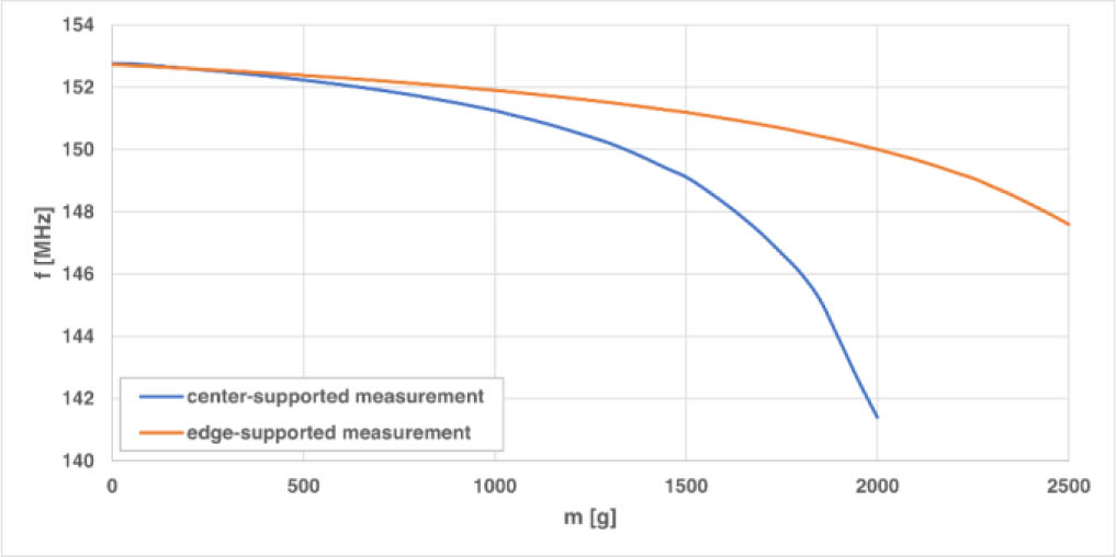
Fig. 21.
Measured dependencies of frequency on force magnitude for center-supported and edge-supported measurements.
Since the behavior of the CCCMB is known, i.e., the conversion between the magnitude of the force acting on the body and the distance between the conductive plates is established, it is not important to show the dependence of frequency f on the distance between the conductive plates G. However, the dependence of the center-supported measurement in Fig. 21, obtained by measurement, has again been supplemented with a theoretical calculation and simulation according to (10). The dependencies obtained in this way are shown in Fig. 22.
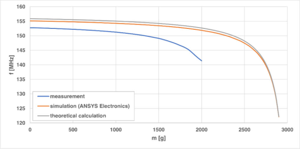
Fig. 22.
Measured, simulated, and theoretically calculated dependence of sensor frequency f on the magnitude of the acting force (weight) m (center-supported measurement).
The measured frequencies for the individual points in Fig. 21 and Fig. 22 are slightly lower than the simulated and theoretically calculated values, but this may not be a major problem. This effect may introduce small deviations in the measured frequency response due to variations in the parasitic inductance of the interconnecting loop between the upper conductive plate and the circuitry located beneath the lower plate. However, as shown in Fig. 22, the measured trend retains the same overall shape as the calculated response, differing mainly by a constant offset. This behavior can be attributed to a reduction in the effective gap between the capacitor plates caused by the thin layer of liquid adhesive used during assembly. This adhesive layer was not included in the simulation model, leading to a systematic shift in the effective capacitance while the overall functional dependence remains unchanged.
Apart from a small shift in the frequency range, this does not affect the functionality and correct operation of the designed sensor as a whole.
4. Conclusion
In this article, the individual blocks of a mechanical quantity sensor based on the RF principle have been theoretically analyzed. After familiarization with the Colpitts oscillator, a CCMB was designed based on research in [17] as a capacitive CCMB (now referred to as CCCMB). The designed body demonstrated excellent results in terms of the dependence of the applied force (weight) on the distance between the conductive plates. These measured dependencies showed linearity of transfer in both measurement cases: the center-supported measurement, where the body was placed on a base with a single contact point, and the edge-supported measurement, where the body was placed on a base with two support points. The dependencies of electrical quantities on mechanical ones were then measured: the dependence of the CCCMB capacitance (formed by conductive plates) on the weight acting on the CCCMB, and the dependence of the oscillation frequency of the designed sensor oscillator on the weight acting on the CCCMB. The measured dependencies of the CCCMB capacitance and sensor frequency were supplemented by simulated dependencies in ANSYS Electronics simulation software and by theoretical calculations based on the formulas given in the article.
In the case of edge-supported measurement, it is possible to change, i.e., increase, the range of the measured force (weight) by approximately 1.5 times while maintaining the same frequency range. The oscillation frequency can also be tuned by changing the inductor, at least one of the fixed capacitors in the oscillator feedback, or by redesigning the CCCMB.
In the laboratory and prototyping phase, the use of PET-G material and additive manufacturing proved suitable, as it enabled sufficient accuracy and good repeatability of measurements while allowing fast, flexible design iterations. However, for final sensor applications, it would be more appropriate to consider materials with more stable, well-defined mechanical and electrical properties, such as metals or ceramics, to further improve long-term stability and reproducibility of the device. The result is an RF-based mechanical sensor that enables wireless transmission of the magnitude of the applied force (weight) data.
The wireless data transmission from the sensor was experimentally validated at distances up to 30 cm, where the received signal remained reliably interpretable. Its performance is strongly dependent on the signal-to-noise ratio (SNR) and the presence of noise or interference within the operating frequency band. Consequently, the achievable wireless measurement range and system limits may be greater under ideal, low-interference conditions.
In conclusion, the sensor's high sensitivity and wide frequency range enable the use of stiffer and more brittle materials, such as ceramics, for CCMB. Although these materials allow only limited electrode displacement compared to flexible CCMB made from PET-G, their stiffness supports sensor miniaturization. With a very small initial electrode gap, even minor mechanical loading can produce significant changes in capacitance and frequency, enabling effective sensor operation despite limited deformation.
In addition, combining the sensor with a spectrum analyzer enables fast, yet precise, weight measurements by directly tracking frequency changes.
Acknowledgment
Funded by the EU NextGenerationEU through the Recovery and Resilience Plan for Slovakia under the project No. 09I05-03-V02-00041 “Novel electrically enhanced wireless method for sensing of mechanical quantities”.