
In recent decades, the field of communications and hexagonal filter technology has witnessed significant advances in design, size, and efficiency, leading to the emergence of new, advanced technologies for guiding electromagnetic (EM) waves. Among these technologies is substrate integrated waveguide (SIW), which combines the advantages of microstrip and waveguide technologies [1]. These technologies are used in the design of microwave components such as resonators, filters, and splitters, and are relied upon to determine and improve system performance, particularly in radar, antenna, and wireless systems applications. Microstrip technology is one of the most widely used guidance technologies in hyperfrequency (HF) systems. It relies on a thin metal conductor strip placed on an insulating layer (substrate), with a metal ground plane beneath. Waves guides are one of the oldest and best methods for transmitting EM waves without significant losses, especially at very high frequencies (GHz). SIW technology is a clever compromise that combines the high efficiency of traditional waveguides with the ease of manufacturing and small size of microstrip technology [2]. A guided channel is formed within an insulating substrate by rows of metal holes (Via) that mimic the walls of a metal guide, with a metal strip at the top and bottom. This is an excellent method for resonators such as the hexagonal resonator, which relies on careful internal structural design to optimize EM field distribution. When the hexagonal resonator is used within a SIW environment, its geometric symmetry is exploited to generate specific resonant modes that are highly efficient at either transmitting or trapping waves. This shape helps improve selectivity and frequency stability, which is required in high-precision filters and sensors. The trisection hexagonal filter, constructed using substrate-integrated waveform technology, offers a promising approach to improving spectral selectivity by introducing transmission zeros at specific frequencies, thereby enhancing the filter's ability to suppress out-of-band interference [3]. This design also reduces the overall filter dimensions without compromising performance or affecting the quality factor (Qe). This improvement is attributed to the adoption of a dual-mode resonator, which leverages two resonant modes to achieve compact and efficient performance. Single-mode and dual-mode rectangular cavity filters based on SIW technology have been discussed in a number of previous studies [2],[3],[4].
The paper first presents the main synthesis steps and the coupling matrix (CM) calculations for the hexagonal SIW filter. After that, [7] describes how to design an additional resonator to the initial structure to subsequently tune the circuit, with each phase requiring a new coupling die for precise adjustments. Then, it demonstrates how to use advanced EM simulation tools, specifically applied wave research (AWR) and HFSS software, to evaluate and optimize filter performance to meet modern technical requirements. Finally, the paper presents the experimental results, which show good agreement with the previously obtained simulation results and confirm the accuracy of the developed design structure, achieving the desired performance initially set.
Fig. 1(a), (b), (c) illustrate the different geometries designed for the target SIW filter based on hexagonal resonators integrated into SIW technology. In the first step, a simple design topology with a single resonator is adopted to provide the main first-order filter structure. In the second step, a second resonator is symmetrically added to evolve the second-order filter structure. Finally, in the third step, another resonator is added to balance the final structure of the target third-order bandpass hexagonal SIW filter with cross-coupling.
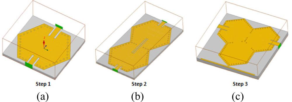
Different steps to design the third-order bandpass hexagonal SIW filter with cross-coupling.
To improve attenuation in the stop band and reduce insertion loss in the pass band, two open terminals at the corresponding input and output ports are connected to a 50 Ω reference voltage. For a physical understanding, an equivalent collector circuit (L1C1) model of the proposed hexagonal bandpass filter is extracted and shown in Fig. 1(a). To analyze and optimize the performance of the proposed filter, this model simulates the actual EM behavior of the physical components within the design, taking into account the effects of the spatial distribution of EM fields across the structure. The simulation of this model was performed using CST Microwave Studio, which relies on the finite integration technique (FIT), an efficient numerical method that accurately represents the interaction of EM waves with various materials in the high-frequency range.
Table 1 presents the hexagonal SIW filter specifications, which constitute a set of criteria for designing hexagonal SIW filters. The 3 × 3 CM of a coupled resonator circuit is a matrix that represents the interactions between three connected resonators in a given system [4]. This matrix contains elements that represent the coupling effects between different resonators. Here we will show a general form of this matrix. Adherence to these specifications is essential to ensuring quality and accurate system performance in applications that require precise signal processing, such as communications, audio equipment, and modern electronic devices.
Hexagonal SIW filter's target specifications.
| Parameter | Value |
|---|---|
| Filter order | 03 |
| Center frequency | 8.15 GHz |
| −3 dB bandwidth | 375 MHz |
| Insertion loss (IL) | < 0.1 dB |
| Passband ripple | 0.0431 |
| Passband return loss | −20 dB |
| FZT (Frequency of zero transmission) | 8.241 GHz |
| Filter function | Tchebychev |
Based on the low-pass prototype filter, the required filter order is chosen to be n = 3 to balance frequency performance and structural complexity [6]. The parameters of this prototype filter are determined according to the reference data in [10], which serves as a basis for tuning the actual bandpass filter.
| g0 | g1 | g2 | g3 | g4 |
| 1 | 1.0316 | 1.1474 | 1.0316 | 1 |
The dimensional design parameters of the filter can be derived from both the center frequency and the absolute bandwidth using the normalized CM. The matrix is then transformed from the standard form to the applicable actual form by applying the denormalization relations described in references [9].
In this work, the proposed hexagonal SIW filter has a center frequency of 7.9 GHz and an FBW of 3.54 %. The transmission zero is located on the upper side of the passband at 8.21 GHz. The simulation results also show a return loss of 25 dB in the passband, indicating a good match between the filter and the feed line. The CM was obtained as described in [6].
Table 2 presents the capacitance C1, inductance L1, and the series impedances Z12, Z23, Z34 used in the total equivalent circuit of the third-order bandpass filter with cross-coupling in AWR are calculated using the following equations [17]:
Values of capacitance C1, inductance L1, impedance Zi.
| Zi | L1, C1 | f |
|---|---|---|
| Z = 50 Ω | L1 = 56.67 nH | 7.9 GHz |
| Z23 = 62.09 Ω | C1 = 0.0071 pF | |
| Z12 = 62.09 Ω |
Fig. 2 represents a circuit consisting of 3 coupled resonators. This model simplifies the filter using ideal electrical circuit elements (capacitors C1 and inductors L1) to quickly and approximately analyze the frequency response. This model was optimized using the advanced design system (AWR) software, which provides advanced tools for the design and analysis of high-frequency circuits, including high-accuracy impedance, coupling, and resonance simulations.
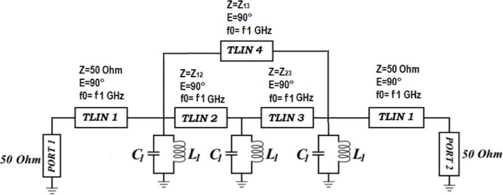
Total equivalent circuit of the third-order bandpass hexagonal SIW filter with cross-coupling.
Fig. 3 shows the simulation by (AWR) design of the filter. As shown in one transmission, zero was observed at 8.21 GHz, indicating signal blocking at this frequency, which is required in filter design to pass the specified frequency range and block other frequencies.
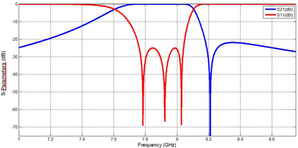
Optimal EM response for a single-band BPF with a single TZ in the upper stopband.
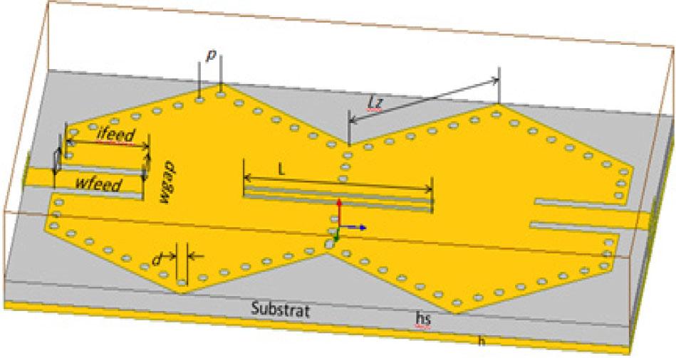
Fig. 4 shows the initial configuration of a first-order bandpass hexagonal SIW filter, with the metal contacts arranged in a precise geometric pattern to optimize EM performance. The design is advanced, enhancing the interaction of EM waves within the cavity and contributing to high efficiency in directing the target frequencies and reducing losses. The design was implemented on a Rogers RO4003 chip, a popular material in high-frequency applications due to its stable electrical properties. This chip features a dielectric constant of ɛr = 3.55, a substrate thickness of h = 0.508 mm, and a very low loss coefficient, tan δ = 0.0027 at 8 GHz, which contributes to reduced losses and improved filter performance.
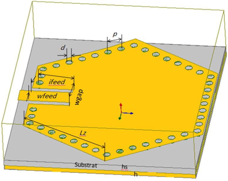
Initial configuration of a first-order hexagonal SIW filter.
An appropriate starting point is considering the SIW structure as a quasi-hexagonal cavity and calculating the hexagonal structure, which, by using the formula obtained in [5], is equal to:
Table 3 below shows the initial geometric dimensions (in millimeters) of the initial structure of the hexagonal SIW bandwidth filter before the design optimization stages were applied.
Dimensions of the first-order hexagonal SIW filter.
| Parameters | d | p | Ifeed | wfeed | wgap | Lz | Wsiw |
|---|---|---|---|---|---|---|---|
| Values [mm] | 2 | 2.98 | 2.9 | 2.6 | 1.5 | 8.4 | 15.98 |
These dimensions enhance the efficiency of EM propagation within the guided structure and improve hexagonal SIW filter performance over the targeted frequency range. To analyze the performance of the designed structure and verify its EM response, numerical simulations were performed using advanced tools. The simulations were conducted using HFSS, a full-wave simulation software for highly accurate EM structures. The calculation of transmission and reflection parameters contributes to evaluating the overall filter performance prior to actual manufacturing. Based on the conventional formula for calculating the resonant frequency of metallic circular resonators [7], the formula was modified to suit the properties of the proposed hexagonal cavity, allowing the initial dimensions of this cavity to be accurately estimated, according to the following formula:
Fig. 5 illustrates the method for extracting the external quality factor of an input/output resonator [14]. This factor is used to determine the efficiency of the resonator's frequency response. The external quality factor is calculated as the ratio of the resonator's natural frequency to the frequency range over which the response drops to half-maximum.
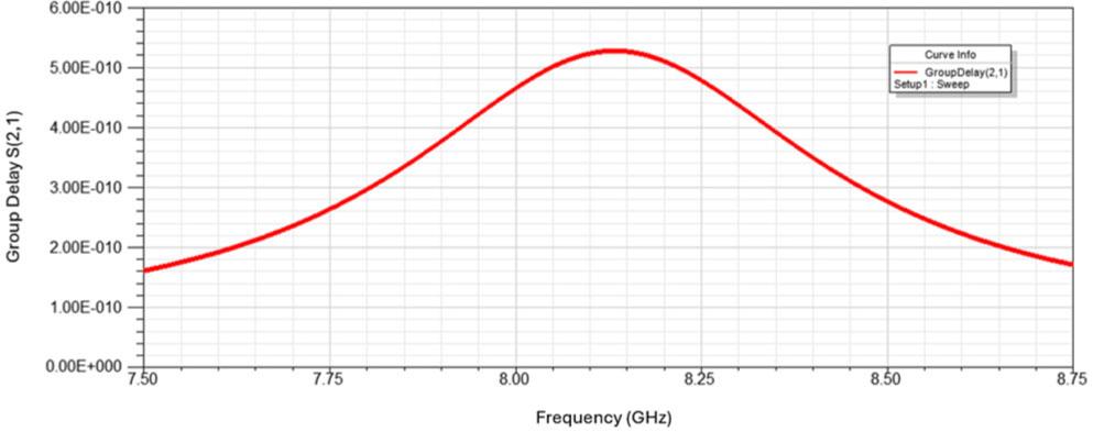
Group delay of the first hexagonal SIW resonator after optimization (p = 1.05 mm, d = 5 mm, wgap = 1.5 mm, Ifeed = 2.8 mm, Wfeed = 2.8 mm, Lz = 8.4 mm).
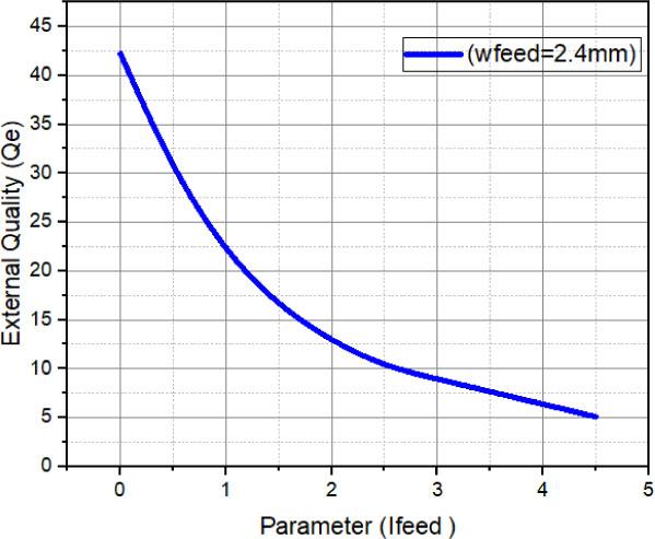
Quality factor of a resonator Qe versus wfeed of the first hexagonal SIW resonator.
Fig. 7 illustrates the computed electric field distribution across the examined resonators, specifically depicting the fundamental mode profiles within a hexagonal cavity resonator at a frequency of f = 8 GHz for angular orientations φ = 90°, 65°, and 45°.
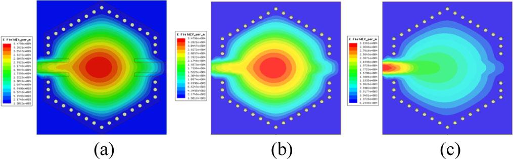
Representation of the electric field distribution of the fundamental modes in a hexagonal cavity resonator at f = 8 GHz, (a) φ = 90°, (b) φ = 65°, (c) φ = 45°.
A noticeable variation in electric field intensity is observed along the magnetic wall of the SIW structure. The field strength fluctuates between its minimum (zero) and maximum values, indicating spatial modulation of the electric field. This distribution highlights the influence of both the structural configuration and electrical characteristics of the SIW, which collectively contribute to variations in the electric field across different regions of the resonator.
Fig. 8 shows a second-order hexagonal SIW bandpass filter configured based on a conventionally proposed parallel-slot defected ground structure (DGS). This DGS topology incorporates a parallel slot etched into the ground plane of the transmission medium. The filter was designed utilizing a transmission line with a characteristic impedance of 50 Ω. Fabrication was carried out on a Rogers RO4003 dielectric substrate, featuring a relative permittivity of ɛr = 3.55 and a thickness of 0.508 mm [13]. The primary slot in the DGS layout has an approximate length of 11.23 mm, while both the slot width and the spacing between its branches are uniformly maintained at 0.64 mm. The DGS element exhibits an overall maximum length equivalent to L, with a total width no greater than 5 × d.
The second-order bandpass hexagonal SIW-DGS filter employing mixed coupling (Lz = 8.4 mm, Ifeed = 1.5 mm, wfeed = 2.8 mm, wgap = 1.5 mm, d = 0.6 mm, p = 1 mm, g13 = 5 mm, L = 10 mm, w = 0.5 mm, s = 0.45 mm).
The S-parameters of the proposed conventional SIW-DGS hexagonal filter were simulated in HFSS using the finite element method (FEM) [20]. The simulation was carried out at the same resonance frequency of 8 GHz, as shown in Fig. 9.
S-parameters of the proposed conventional SIW-DGS filter.
In the context of analyzing the EM interaction between the hexagonal SIW-DGS resonators, these resonators were arranged side by side, separated by rows of metal holes, as described in reference [22]. By monitoring the system's response at different frequencies, the coupling coefficient (K) was determined using (16). However, the results showed that the coupling value obtained with this method is less than the ideal value required by the design. The resulting graph (Fig. 10) is a design tool for determining the exact dimensions of the slots or gaps that control the degree of coupling between the resonators [15].
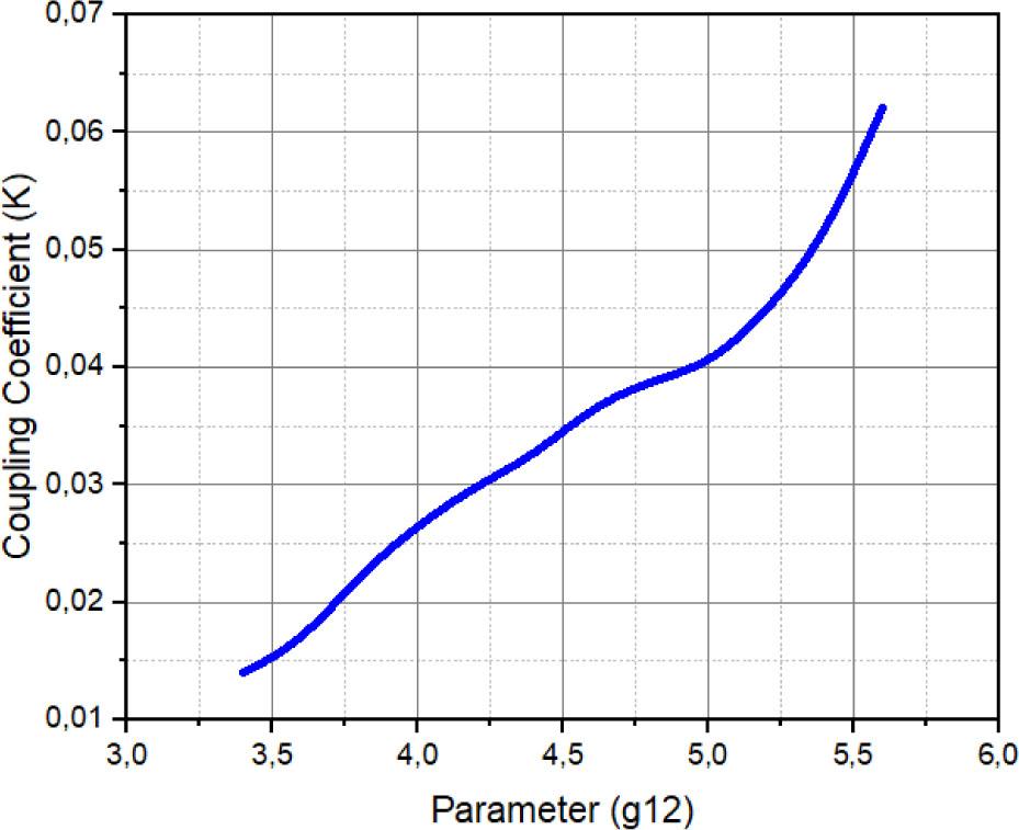
Extracted coupling coefficient K versus g12 for the second-order bandpass hexagonal SIW-DGS filter.
Fig. 9 shows the EM simulation setup to determine the coupling between resonators 1 and 2 in a hexagonal SIW-DGS filter. Through this simulation, the interactions between the resonators are analyzed, and coupling coefficients are extracted to improve the filter's performance in filtering the desired frequencies. EM simulation is a powerful tool for understanding these interactions and achieving the ideal balance between coupling strength and frequency response of the filter. Using the same approach described for extracting the resonator coupling, a design curve for K is produced that shows the relationship between the coupling coefficient and the geometric properties of the filter. Table 4 summarizes the coupling matrix elements Mi,i+1 and the corresponding iris widths gij of the third-order hexagonal SIW-DGS bandpass filter.
Coupling and iris widths gij of the third-order hexagonal SIW-DGS bandpass filter.
| Mi,i+1 | K | gij [mm] |
|---|---|---|
| M12 = M23(0.0453) | 0.0465 | g12 = g23 = (5.22) |
| M13(0.0621) | 0.0623 | g13 = (5.6) |
Fig. 11 shows the electric field distributions for different phase angles: φ =0°, 90°, 135°, and 180° in the hexagonal SIW-DGS filter. It is observed that the electric field crosses all four resonant wavelengths when the proposed filter is operated at 8 GHz, as simulated in HFSS.
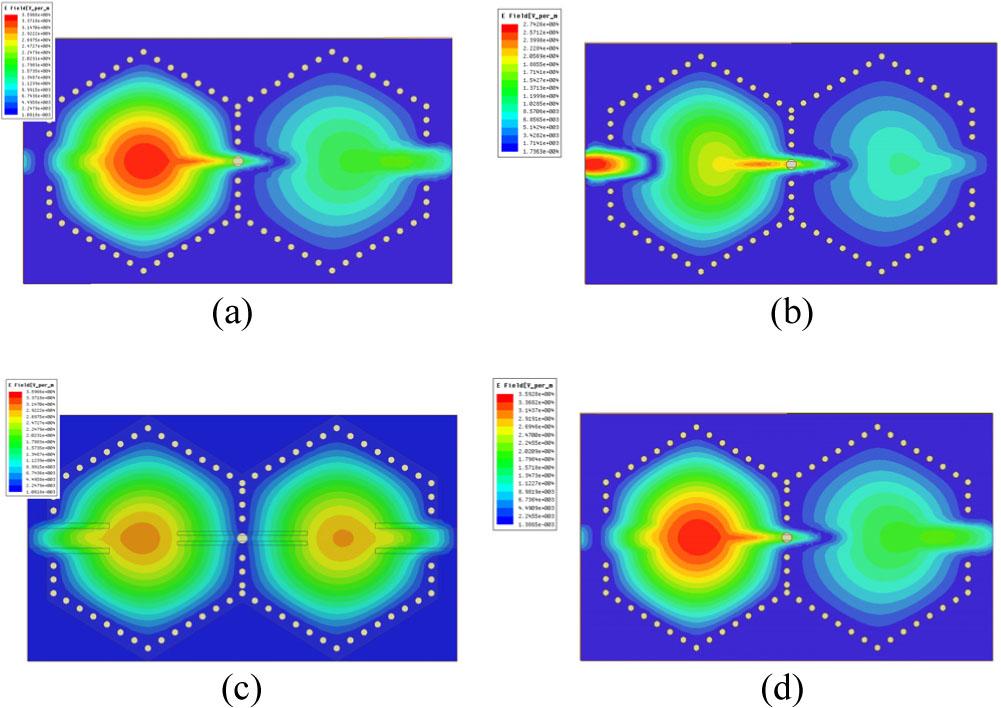
Representation of the electric field distribution of the second-order hexagonal SIW-DGS filter at f = 8 GHz, (a) φ = 0°, (b) φ = 45°, (c) φ = 90°, (d) φ = 180°.
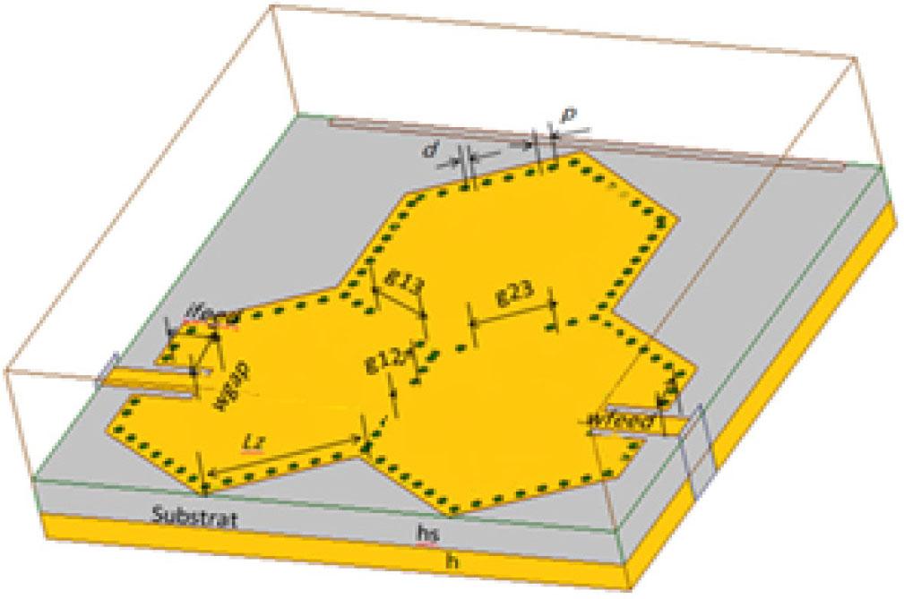
In this section, a third-order bandpass hexagonal filter was designed and simulated using SIW technology. This was based on a Rogers RO4003C™ substrate with a thickness of 0.508 mm, a dielectric constant ɛr = 3.55, and a loss coefficient tan δ = 0.0027 [11]. Since the required resonant frequency is 8 GHz, the initial dimensions were determined according to the basic frequency calculation equation (12). The diameter of the metal screws (conductive holes) was set to 0.5 mm, with a spacing of 1 mm, to ensure good conductivity and prevent EM radiation leakage [12].
The initial dimensions of the third-order passband hexagonal SIW-DGS filter structure are shown in Table 5, while the design topology is shown in Fig. 12. The three resonators are connected using an inductive iris, while the two end resonators are coupled to a 50 Ω microstrip line for excitation and loading purposes. This configuration aims to generate a sharp transition at the band edge, resulting in a primary transmission zero (TZ1) near the cutoff frequency, enhancing the filter's selectivity and efficiency in blocking out-of-band signals [18].
The initial dimensions of the third-order passband hexagonal SIW-DGS filter.
| Parameters | Symbol | Value [mm] |
|---|---|---|
| Microstrip line | Width | W50 = 1.2 |
| L50 = 5.6 | ||
| SIW characteristics | Width | Wsiw = 15.98 |
| Pitch of vias | p = 1 | |
| Diameter | d = 0.5 | |
| Iris characteristics | Distance | g12 = 5.2 |
| g13 = g23 = 5.6 | ||
The third-order bandpass hexagonal SIW-DGS filter design with cross-coupling.
To analyze the frequency performance of a hexagonal bandpass filter built using SIW, a precise HFSS simulation was performed to evaluate the propagation coefficients, particularly the reflection (S11) and transmission (S21) coefficients.
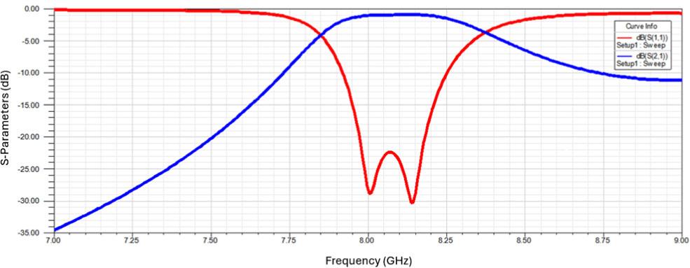
As shown in Fig. 13, the simulation results indicate that the filter's center frequency is 7.9 GHz, with a third-order filter bandwidth of 0.27 GHz [23]. The frequency response demonstrates satisfactory performance, with |S11| less than −20 dB across the 7.77 GHz to 8.04 GHz range, indicating its high efficiency in reducing reflections in this band and achieving good signal transmission at the desired frequencies.
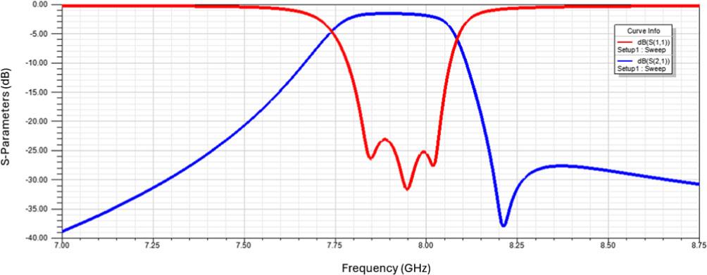
EM response for the third-order bandpass hexagonal SIW-DGS filter with cross-coupling.
Fig. 14 shows the simulation results for the proposed third-order bandpass hexagonal SIW-DGS filter. The simulation results were compared using HFSS with the CM extracted from the equivalent circuit model. The results showed good agreement between the HFSS and circuit simulations. The figure shows that the filter's center frequency is 7.9 GHz, while the cutoff frequencies (at −3 dB) are 7.74 GHz and 8.08 GHz, respectively, yielding a bandwidth of 340 MHz. The insertion loss within the passband is 1.58 dB. Thus, the proposed filter operates efficiently at 7.9 GHz, with good agreement between the simulation results and the CM.
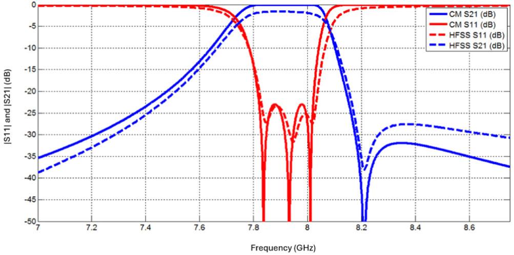
Comparison of the EM response of the third-order bandpass hexagonal SIW-DGS filter extracted using CM and HFSS.
Fig. 15 shows the simulated electric field distributions at the resonance frequency of 8 GHz for different phase angles in the trisection hexagonal SIW-DGS filter.
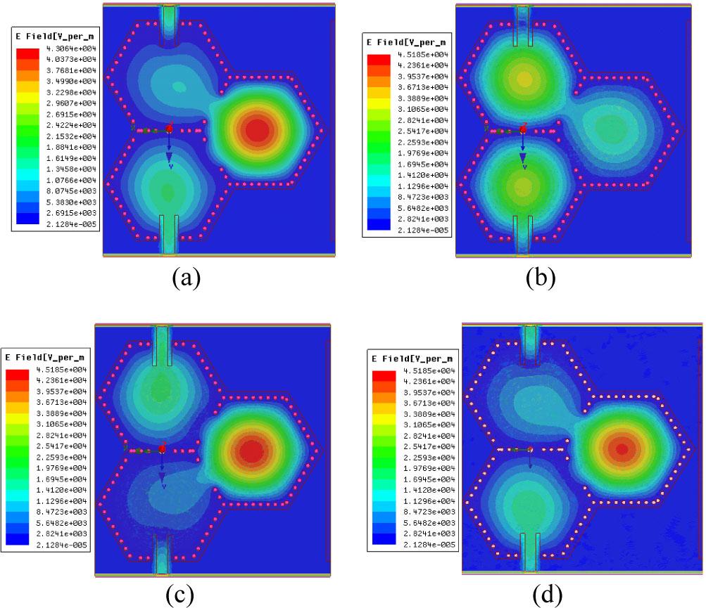
Simulated electric field distributions at the resonance frequency at f = 8 GHz, (a) φ = 0°, (b) φ = 45°, (c) φ = 90°, (d) φ = 180°.
As shown in Fig. 15, the strongest electric field distribution is concentrated at the center of the resonator, indicating resonance at this frequency. It is observed that the 8 GHz EM wave travels efficiently to the output port, confirming the effectiveness of the filter design at this frequency.
A hexagonal SIW-DGS bandpass filter, as shown in Fig. 16, was designed and fabricated using a Rogers RO4003 substrate. This substrate has a dielectric constant of 3.55, a thickness of 0.508 mm, and a very low loss coefficient of 0.0027. The center frequency of the hexagonal filter was chosen at 8 GHz. The hexagonal shape is easy to modify to suit various design requirements, such as bandwidth or number of poles. This makes it suitable for a variety of environments, especially in aviation and wireless communications applications. Fig. 16 shows an image of the fabricated hexagonal SIW filter, which has overall dimensions of 22.9 mm × 17 mm.
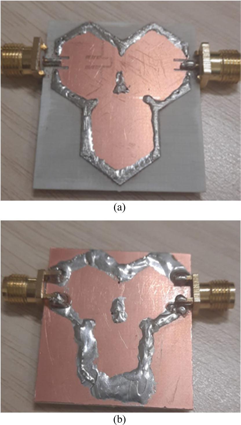
The photograph of the implemented third-order bandpass hexagonal SIW-DGS filter, (a) top view and (b) bottom view.
Fig. 16 shows that the overall dimensions of the circuit, excluding two 1.2 mm wide feed lines, are 17 mm × 22.9 mm. To verify the accuracy of the adopted design methodology, measurements were performed on the fabricated hexagonal frequency filter using a Rogers RO4003 vector network analyzer [19].
The simulated and measured results of the frequency response of the proposed hexagonal SIW are presented in Fig. 17. These results demonstrate good agreement between the simulated and measured performance, confirming that the software predictions match the actual performance and demonstrating the accuracy and efficiency of the developed filter design based on SIW-DGS techniques.
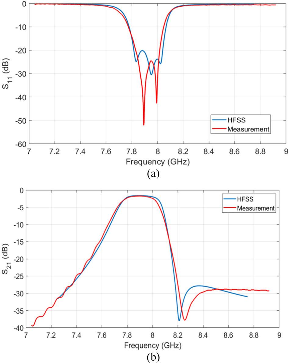
Measured vs simulated results of the third-order bandpass hexagonal SIW-DGS filter with (a) insertion loss and (b) return loss.
Fig. 17 presents a comparison between the simulation results (blue line) and the experimental measurements (red line). The measured passband at 3 dB spans 7.77–8.05 GHz, corresponding to a relative bandwidth of 3.54 %. The measured return loss in the range was over 23 dB, while the minimum insertion loss was 1.58 dB. It is noted that the fluctuation within the band is less than 0.2 dB. It is worth noting that the measured S parameters include two vertical transitions and ultra-small (SMA) connectors soldered to the ends of the BPF filter, designed to connect the input/output ports [22]. Therefore, the minimum insertion loss of the filter is definitely less than 1 dB. The first transition zero is located at 8.21 GHz, enhancing selectivity while maintaining good performance in the upper stopband, where the attenuation level exceeds 27 dB starting at 8.35 GHz.
The results of calculations (obtained from mathematical equations), simulations (obtained using HFSS), and actual measurements (obtained using the realized design) are presented together in Table 6 to illustrate the extent to which the results agree in terms of EM response, which validates the proposed SIW-DGS filter design for the desired applications.
Comparison of calculated, simulated, and measured results for the developed third-order hexagonal SIW filter.
| Operation | Calculation | Simulation | Measurement |
|---|---|---|---|
| Center frequency [GHz] | 7.9 | 7.903 | 7.898 |
| Lower −3dB Cut-off [GHz] | 0.1 | 1.58 | 1.62 |
| Bandwidth [MHz] | 279.66 | 270 | 272 |
Table 7 summarizes a comparison with other filters, demonstrating that the proposed filter offers superior size reduction and excellent frequency performance. This comparison shows that the proposed SIW-DGS filter design is among the best in terms of volumetric efficiency compared to conventional resonator-based designs [10].
Comparison of the designed third-order hexagonal SIW-DGS filter to other reported filter designs.
| Ref. | f [GHz] | FBW [%] | Insertion loss [dB] | Return loss [dB] | Circuit size |
|---|---|---|---|---|---|
| [21] | 5.00 | 8.00 | 1.92 | 20 | 45 × 25 × 0.542 |
| [22] | 8.00 | 13.75 | 1.20 | 20 | 35 × 30 × 0.849 |
| [23] | 9.82 | 2.10 | 0.74 | 24 | 50 × 30 × 0.821 |
| Proposed design | 7.90 | 3.54 | 1.85 | 23 | 17 × 22.9 × 0.542 |
NOTE: FBW = BW/f, where BW is absolute bandwidth BW = f2 − f1
In this paper, a high-performance third-order bandpass hexagonal SIW-DGS filter is designed for modern communications applications. The proposed filter was optimized in HFSS using an accurate mathematical model. The filter presents an insertion loss of 1.85 dB and a return loss of −23 dB at the center frequency of 7.9 GHz with a FBW of 3.54 %, indicating an efficient EM response within the desired frequency band. The filter is realized using an RT/Rogers 4003 substrate with a dielectric constant of ɛr = 3.55, a tan δ = 0.0027, and a thickness of 0.508 mm. It is observed that the calculated, simulated, and measured results are in good agreement, validating the efficiency and accuracy of the proposed design, which can be used in several applications, such as mobile, radar, and satellite systems, in addition to worldwide interoperability for microwave access (WiMAX) applications.