
Table 1.
Summary of key related works and their limitations.
| Method / Protocol | Optimization technique | Security mechanism | Parameters considered | Limitations |
|---|---|---|---|---|
| Ex-GWO, I-GWO [5] | GWO variants | None | Energy, distance, traffic load | Poor adaptability in dynamic networks, high complexity |
| Fuzzy-GWO [8] | Hybrid fuzzy + GWO | None | Energy efficiency | Performance degradation in heterogeneous networks |
| SEAMHR [7] | Metaheuristic analysis | Counter-mode cryptography | Delay, energy, security | Security issues due to CTR reuse, high overhead |
| SEHR [9] | Heuristic-based routing | Lightweight cryptography | Energy-aware routing | Integrity flaws, limited energy optimization |
| ESMR [10] | Secret sharing | Key sharing + multi-hop | Energy, security | No mobility support, ignores QoS metrics |
| IBFA [12] | Blowfish with CM-MH | Symmetric encryption | Energy, security | No authentication, high complexity, vulnerable patterns |
| GMPSO [16] | Genetic mutation PSO | None | Energy efficiency, throughput | High controller overhead, ignores trust, longer flow times |
| BOA-ACO [15] | BOA + ACO | None | Cluster-head routing, energy | No built-in security, limited scalability |
| IEE-LEACH [20] | Improved LEACH hybrid routing | None | Energy | Focuses only on lifespan, no security |
| HPSO-ILEACH [18] | PSO + Improved LEACH | None | Energy aggregation | Lacks robust trust/security |
| PSOGA [14] | PSO + GA hybrid | None | Energy, packet transmission | Limited scalability, no lightweight security |
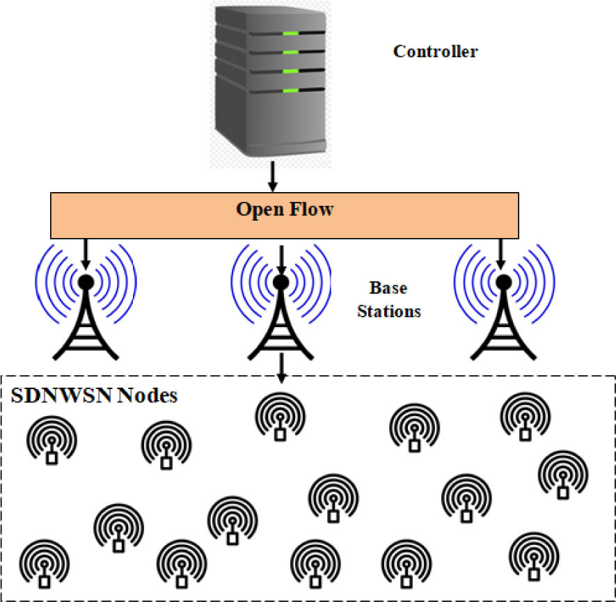
Fig. 1.
Proposed system model overview.
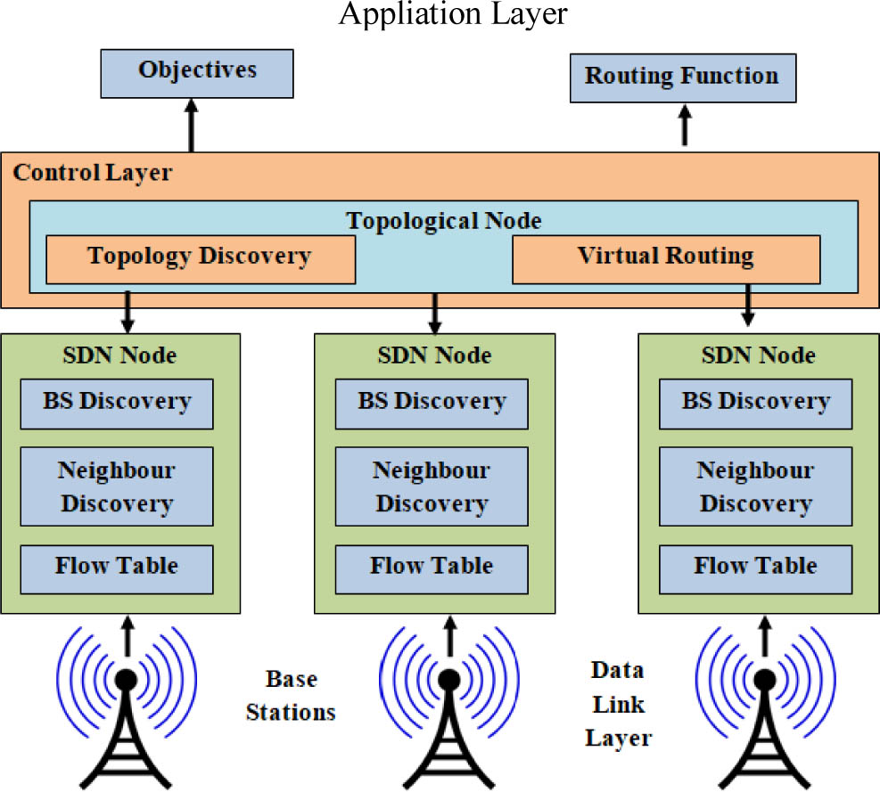
Fig. 2.
Proposed system architecture for SDWSN.
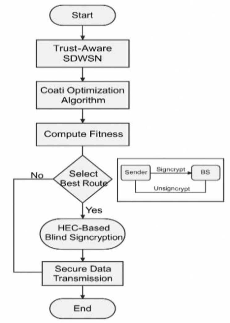
Fig. 3.
COA–HEC secure routing flowchart.
Table 2.
Details of simulation parameters setup.
| Parameter | Values |
|---|---|
| Simulator model | NS-3.26 |
| Sensor nodes count | 50, 100, 150, 200, 250 |
| Simulation area | 500×500 m |
| Optimal path finding protocol | COA |
| SDN controller count | 1 |
| Base station | 3 |
| Size of packet | 512 bytes |
| Initial energy | 50 J |
| Simulation time | 300 sec |
| Transmission range | 250 m |
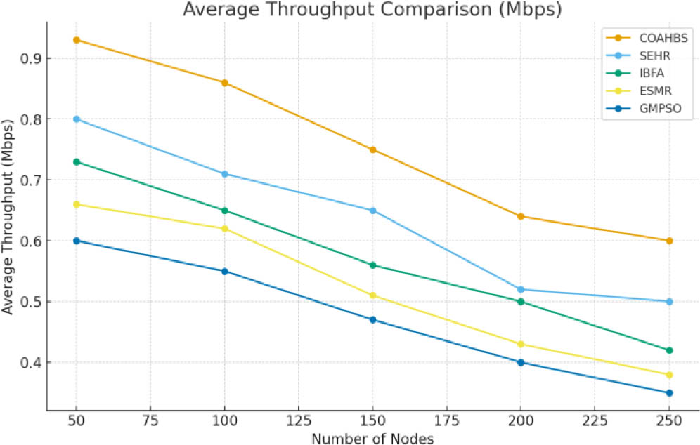
Fig. 4.
Average throughput analysis.
Table 3.
Average throughput comparison [Mbps].
| Nodes | COAHBS | SEHR | IBFA | ESMR | GMPSO |
|---|---|---|---|---|---|
| 50 | 0.93 | 0.80 | 0.73 | 0.66 | 0.60 |
| 100 | 0.86 | 0.71 | 0.65 | 0.62 | 0.55 |
| 150 | 0.75 | 0.65 | 0.56 | 0.51 | 0.47 |
| 200 | 0.64 | 0.52 | 0.50 | 0.43 | 0.40 |
| 250 | 0.60 | 0.50 | 0.42 | 0.38 | 0.35 |
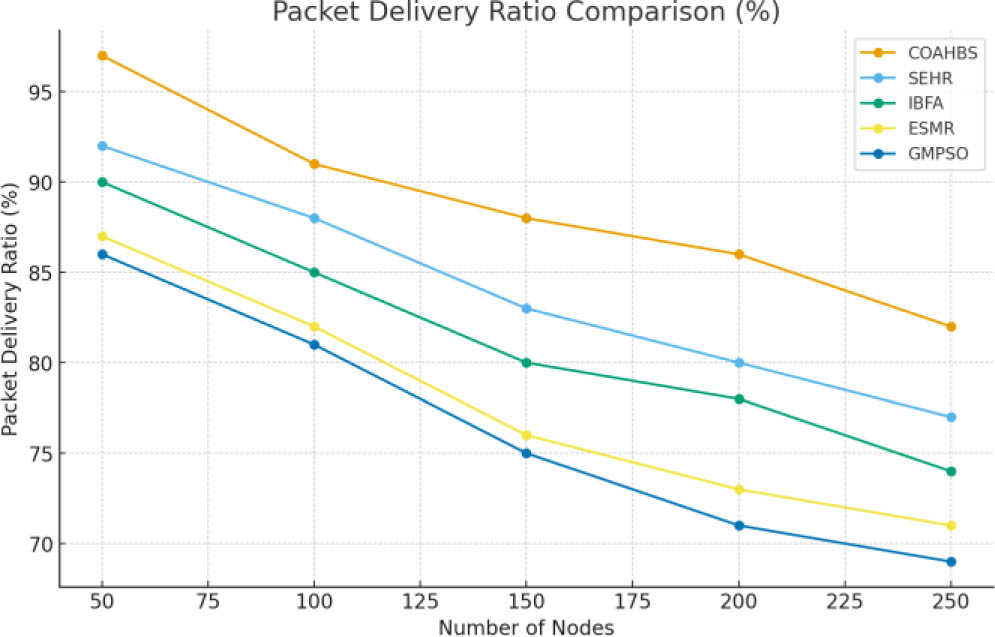
Fig. 5.
Analysis of PDR.
Table 4.
PDR comparison [%].
| Nodes | COAHBS | SEHR | IBFA | ESMR | GMPSO |
|---|---|---|---|---|---|
| 50 | 97 | 92 | 90 | 87 | 86 |
| 100 | 91 | 88 | 85 | 82 | 81 |
| 150 | 88 | 83 | 80 | 76 | 75 |
| 200 | 86 | 80 | 78 | 73 | 71 |
| 250 | 82 | 77 | 74 | 71 | 69 |
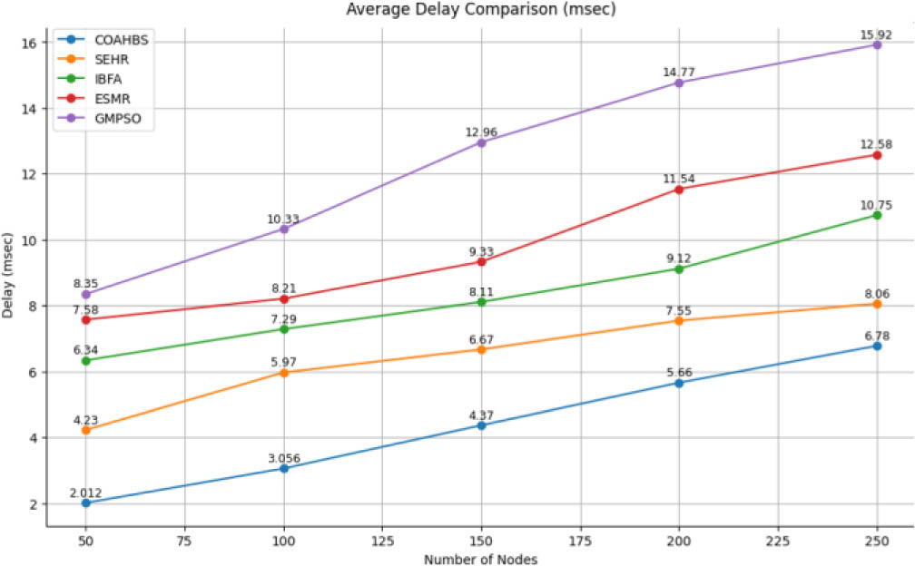
Fig. 6.
Average delay analysis.
Table 5.
Evaluation of average delay comparison [msec].
| Nodes | COAHBS | SEHR | IBFA | ESMR | GMPSO |
|---|---|---|---|---|---|
| 50 | 2.012 | 4.23 | 6.34 | 7.58 | 8.35 |
| 100 | 3.056 | 5.97 | 7.29 | 8.21 | 10.33 |
| 150 | 4.37 | 6.67 | 8.11 | 9.33 | 12.96 |
| 200 | 5.66 | 7.55 | 9.12 | 11.54 | 14.77 |
| 250 | 6.78 | 8.06 | 10.75 | 12.58 | 15.92 |
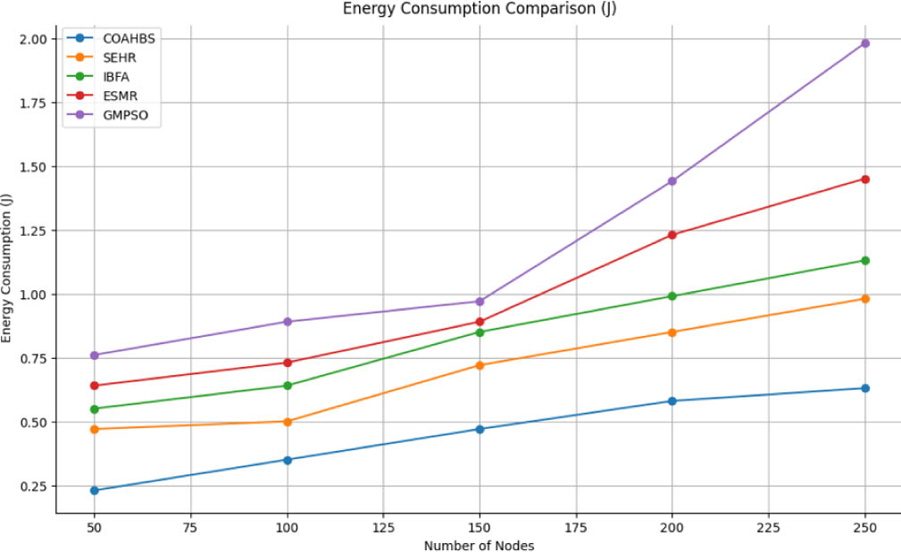
Fig. 7.
Energy consumption analysis.