A CNC machine tool shortcut converts tool path and feed rate data into servo system sample interval reference points. The machine's true position, as indicated by the motor axis encoders, can be compared with the reference locations using closed-loop position and velocity control [1]–[4].
Nowadays, parametric curves are widely used in computer-aided design (CAD). in the automotive, aerospace, and mould design industries [5]–[9]. Parametric curves have different shapes, which are the most important [10]. They are the Bezier curve, the B-Spline curve, the third-degree spline curve, and the non-uniform rational b-splines (NURBS) curve. Among these curves, the NURBS curve is the most popular and is used as a standard curve [11]–[15]. In addition to linear and circular interpolation, new numerically controlled machine toolsalso offer the possibility of parametric interpolation; the conducted research has shown that parametric interpolation reduces the fluctuations of the feed rate and string errors and shortens the machining time compared to linear and circular interpolation [16]–[21].
The accurate adjustment of the feed rate is especially important in high-speed machining, since in this case the values of the acceleration range and the acceleration derivative (Jerk) are very large [22], [23]. In addition, the inability of the finder to maintain the feed rate can lead to self-excited vibrations in the tool (tool chatter) or tool failure [24]–[27]. Recent advancements in robotic motion control have emphasized the importance of vibration management in two-inertia systems [28], [29]. While numerous advancements in intelligent motion control have emerged from the fields of robotics and mechatronics, their direct integration into CNC interpolation frameworks remains limited. For example, recent studies have explored load-side acceleration control using single inertialization compensators and jerk observers to suppress vibration in robotic actuators [30], as well as the development of intelligent AC servo drive systems with embedded diagnostic and vibration attenuation mechanisms [31]. In addition, velocity control strategies based on disturbance observers [32], as well as learning-from-demonstration and contact-aware motion planning techniques [33], have shown promising results in flexible manipulation and failure recovery tasks [34].
Although these methods contribute valuable insights into disturbance rejection, dynamic adaptability, and sensor-driven control, they are primarily designed for robotic systems characterized by high degrees of freedom and environment-dependent variability. In contrast, CNC machining requires ultra-precise, high-speed trajectory execution with stringent constraints on geometric accuracy and system determinism [35], [36]. Although we acknowledge the conceptual value of these mechatronic strategies, our work is grounded in the specialized domain of CNC interpolator design and focuses on feed rate-adaptive and curvature-aware motion planning techniques that directly address the challenges of toolpath accuracy, minimizing machine stress, and ensuring real-time implementation in industrial CNC systems [37], [38].
Furthermore, although several advanced interpolators have been proposed in the academic literature, widespread commercial use remains limited. Many existing CNC controllers still rely on curvature-insensitive, fixed-interval interpolation schemes, which introduce significant tracking errors, especially during high-speed transitions or sharp corners. The approach proposed in this study addresses these gaps by integrating a predictive, PH-based interpolation framework that not only reduces geometric deviation but also ensures bounded dynamic behavior consistent with industrial motion constraints.
These finders calculate the parameter values for consecutive reference locations. The use of Taylor series expansion to eliminate high-order terms causes a clipping error in the calculations [24], [39].
The Pythagorean-hodograph (PH) curves can represent the tool path to avoid cutting mistake. The interpolation equation derived for this curve delivers high accuracy and remains flexible across different speed regimes, accommodating both fixed- and variable-advance conditions. [17], [40], [41].
Several methods for parametric curve interpolation have been developed. Beh et al. introduced a Taylor series expansion-based parametric interpolator [42], [43]. Feroki et al. [24] accurately calculated the Taylor series expansion coefficients up to the third-order term. In [40], [44]–[46], parametric interpolation on the PH curve considering the feed rate was proposed. However, this solution does not contain a way to adjust the progress based on the curve geometry. In [47], an interpolation algorithm with variable forward speed was presented. This algorithm changes the feed rate so that the string error does not exceed the permissible limit. In [48], an algorithm for changing the feed rate based on the geometric properties of the curve was presented. Since these algorithms do not consider the changes in the forward speed, rapid changes in the curvature of the path can cause an excessive increase in the acceleration or the derivative of the acceleration. Tsai et al. provided NURBS. This algorithm considers geometric errors and errors caused by servo system dynamics at the same time. This approach does not consider Taylor series expansion-based interpolation issues.
As vendors develop computer codes, the CNC machines’ unique nature limits input adjustments and additions. In the paper, GRBL-Arduino drives a tiny two-axis CNC machine [49], [50]. After Img2CAD converts a JPG or PNG hexagonal or circular image into a drawing file, UG NX creates the G-code. GRBL-Arduino controllers receive G-code files from the Arduino Uno with GRBL shield V5 hardware's universal gcode sender (UGS) application. UGS's G-code visualizer displays the drawing before execution. The G-code drives two stepper motors, each rated at 2.6 kgf·cm (≈ 0.255 N·m), on the x and y axes to design CNC forms. This study explains the design of a three-axis CNC machine with a z-axis motor using the third intrinsic stepper driver of the GRBL Shield V5.
Most aircraft components are large, complex, and thin-walled, so machining performance is critical. Performance enhancement needs machining process monitoring. In [51]–[55], several data sources to increase the milling quality and efficiency through position-oriented process monitoring were used. Internal numerical control system data can relate the cutting position to the cutting force, acceleration, and spindle power signals. Optimization of processes depends on result monitoring. Experimental tests on aircraft structural and blade components shows that this approach improves thin-walled part machining. Feed-rate optimization reduced the titanium-alloy rough-milling time from 19.1 h to 14.4 h (−4.7 h; −24.6 %) and lowered cutter consumption from five to three tools (−40 %). Position-oriented process monitoring reduced vibrations and chatter and improved machining quality.
Dynamic considerations and joint configurations cause mode shifts, making the regenerative chatter theory unreliable for robotic milling. CNC machines have shown that it works. Experiments [56] support the regenerative chatter hypothesis in robot high-speed milling. First, milling robot modal tests estimate the stability lobes using a zero order approximation, and then high-speed slotting tests confirm them. The results support robotic high-speed milling. Further laser tracker and displacement sensor tests show that low-frequency robot structural modes cause most of the prediction errors in the zero order approximation, especially in low-speed milling. The regenerative chatter hypothesis for robotic high-speed milling must account for robot stiffness, trajectory following inaccuracy, forced vibrations, and motion coupling.
In high-precision CNC machining, achieving smooth and accurate tool motion remains a significant challenge, particularly when executing geometrically intricate trajectories at high feed rates [57], [58]. Recent studies have emphasized the critical role of robust contour tracking, vibration suppression, and surface integrity control in fulfilling industrial machining requirements [59], [60]. Experimental results indicate that surface quality and dimensional stability are sensitive to dynamic variations in tool–workpiece interaction, tool wear progression, and thermal-mechanical coupling effects, particularly in advanced operations such as laser-assisted or high-speed turning processes [61]. These insights collectively reinforce the need for predictive interpolation frameworks that can dynamically adapt velocity and acceleration profiles based on localized curvature and system dynamics, ensuring geometric accuracy, stability, and machining precision in complex, multi-axis environments [62], [63].
Building on these advancements, recent contributions have focused on the development of sophisticated control strategies to improve feedrate regulation and reduce path-following errors in high-performance motion systems [64], [65]. In particular, adaptive robust control frameworks that incorporate intelligent uncertainty modeling have shown promising results in maintaining motion stability under dynamic and nonlinear operating conditions [66], [67]. In parallel, advanced trajectory tracking techniques based on internal model principles have demonstrated their effectiveness in minimizing both steady-state and transient deviations during the execution of complex paths [68], [69]. These developments highlight the growing importance of predictive interpolation schemes that use real-time curvature feedback and dynamic system characterization to achieve high-fidelity, smooth, and stable motion control in precision CNC machining environments [70], [71].
This article presents a novel interpolation algorithm based on a hybridization of Pythagorean-hodograph (PH) curves and NURBS representation, with an integrated predictive, feed rate-adaptive control strategy. The method includes four key modules: sharp corner detection, PH curve generation, smooth speed profile construction, and dynamic feed rate adaptation. In contrast to traditional NURBS interpolators, which often struggle with sharp curvature changes, string (chord) errors, and instability at high speeds, this algorithm proactively adapts the interpolation steps according to local geometric complexity and system dynamics. It accounts for servo lag, feed rate fluctuations, and geometric discontinuities to ensure smoother tool motion and consistent path accuracy. In this way, faster machining speeds, reduced execution time, and improved contour accuracy are achieved without increasing computational complexity. Comparative simulations and experiments validate the algorithm’s superiority over conventional interpolation techniques in terms of accuracy, smoothness, and real-time responsiveness. Key innovations of this work:
Introduction of a predictive PH-based interpolation strategy that adapts to real-time feed rate variations.
Integration of sharp corner detection and curvature-aware trajectory modification using PH segments.
Generation of a bounded-acceleration speed profile for smoother transitions and reduced mechanical stress.
Compensation for servo lag, chord errors, and curvature-induced deviations during high-speed execution.
Validation through simulations and experiments confirming greater geometric accuracy and efficiency compared to classic Taylor-based or fixed-step NURBS interpolators.
We assume that C(u) is a NURBS curve with the equation [72]–[74]:
In (1), Pi represents control points, Wi is the weight of the control point Pi, n + 1 is the number of control points, and P is the degree of the NURBS curve. Ni,p(u) is the B-Spline basis function calculated by the following recursion relations:
In the above relations, {u0, … , un+p+2} represents the nodal vector and the interpolation parameter u. For the interpolation of the NURBS curve, a Taylor series expansion is used up to the second order approximation. In this way, the interpolation equation for determining the uk parameters related to the successive reference points for the servo system is obtained as follows:
Substituting the derivative values into (4) gives the Taylor series expansion as follows [24]:
In (5), C″(uk) and C′(uk), Ts, Ak, Vk, the sample period acceleration and NURBS curve first and second-order derivatives are given. Using the De Boer method, the values for C″(uk), C′(uk), and C(uk) can be calculated in real time [16].
A PH curve is a special class of polynomial parametric curves, defined by a parametric formulation that allows closed-form arc length and feed rate interpolation.
Moreover, PH is a polynomial parametric curve with parameter ξ, defined by parametric differentiation as r(ξ) = (x(ξ), y(ξ)). As shown in [40], [74], each component is:
Using (6), components x′(ξ) and y′(ξ) are in the form of polynomials that apply to the Pythagorean relation:
In relation to (7):
It represents the parametric speed on r(ξ). In this way, by replacing the polynomials u(ξ) and v(ξ) in (6) and integrating, the components of the curve r(ξ) are obtained. A quintic PH curve is constructed on the surface face by substituting quadratic Bernstein polynomials into the parametrization:
It is obtained in (6) and integration [11]–[14]. In this research, the forward speed is defined as a function of time to determine the interpolation equation. If the function of the advancing speed in terms of time is v(t) and its indefinite integral is F(t), the interpolation equation solves the following equation.
In (10), s(ξ) is the function of the length of the PH curve [40].
At each sampling instant Δtk = k Δt(k = 1,2, …), the real-time numerical-control interpolator computes the corresponding parameter vector ξ(tk) = [ξ1(tk),ξ2(tk),…]T relative to the reference trajectory. The following polynomial equations have these roots:
Equation (11) can be solved using the Newton-Raphson method to find the value ξk as:
Moreover, when solved with the initial value
System architecture and the details of the predictive algorithm based on PH are presented in this part. This algorithm works as a numerical computer controller and consists of three main programs: the CNC commands translator, which generates reference points, the motion controller of the CNC translator reads the numerical control commands from the file and writes them as numerical control blocks in the memory stores, and the reference point generator creates consecutive reference points for the servo system based on the algorithm presented. The movement of the X-Y table controlled by the motion controller using the reference points.
The algorithm for generating reference points in the proposed interpolation method consists of five main components, each contributing to improved path accuracy and motion smoothness in real-time CNC applications:
Sharp corner detection: This module examines the upcoming NC blocks to detect sharp corners by analyzing changes in direction and curvature. Once detected, the curve is segmented into smaller sections accordingly to enable local smoothing and error control.
PH curve generation: Each sharp corner region is approximated by a PH curve to ensure continuous curvature and analytical arc length calculation. This conversion enables higher-order continuity and efficient interpolation.
Initial speed profile generation: A preliminary speed profile is created based on the chord error constraints, maximum allowable feed rate, acceleration, and jerk limits. This profile ensures that the geometric following error remains within the prescribed bounds under nominal conditions.
Predictive curvature-based feed rate adjustment: The preliminary speed profile is refined by curvature-aware feed rate modulation. Local curvature and a lookahead window are used to adaptively scale the feed rate at each point, ensuring that the tangential acceleration remains within the machine limits. This predictive layer prevents abrupt deceleration or overshoot near tight curves and improves motion smoothness during real-time execution.
Dynamic detection and correction: The speed profile is further corrected to address real-world factors such as servo lag, sudden parameter changes, and system dynamics. This ensures that the trajectory remains feasible and safe even under the actual machine constraints.
Finally, the real-time motion controller uses this optimized interpolation sequence to control the X–Y table position, achieving precise toolpath tracking during high-speed milling. The mathematical details of each module are explained in more detail in the following sections.
Sharp corners are very important in predictive algorithms. In this article, the sharp corner refers to the range in which the path following error is highly sensitive to the forward speed. Threfore, the forward speed must be reduced in this range to follow the path with proper accuracy. In addition, the fluctuations of the forward speed in this range should be minimized. For this purpose, this curve range is replaced by the PH curve, for which accurate interpolation is possible. Two conditions can be used to determine the sharp corner. First, the sharp corner derivative of curvature must be zero. Mathematically:
In (13), κ(u) represents the curvature and it is defined as follows:
Using the first condition alone is not enough to determine the sharp corners of the curve because, in this condition, the effects related to the feed rate are not considered [3]. For this purpose, in order to add the effects of advancement, the second condition is used as follows. Based on this condition, to consider a region of the curve as a sharp corner, its curvature must exceed the boundary value of κth. This boundary value is defined as follows:
In (15), Amax is the maximum acceleration and Vmax is the numerical control block input forward speed. The second criterion examines if centrifugal acceleration surpasses the relative extrema's maximal acceleration threshold [3]. If necessary, a PH curve substitutes the sharp corner. The domain advancement pace will be better controlled using this method. Fig. 1 shows how the two situations affect the acute angles AB and CD.
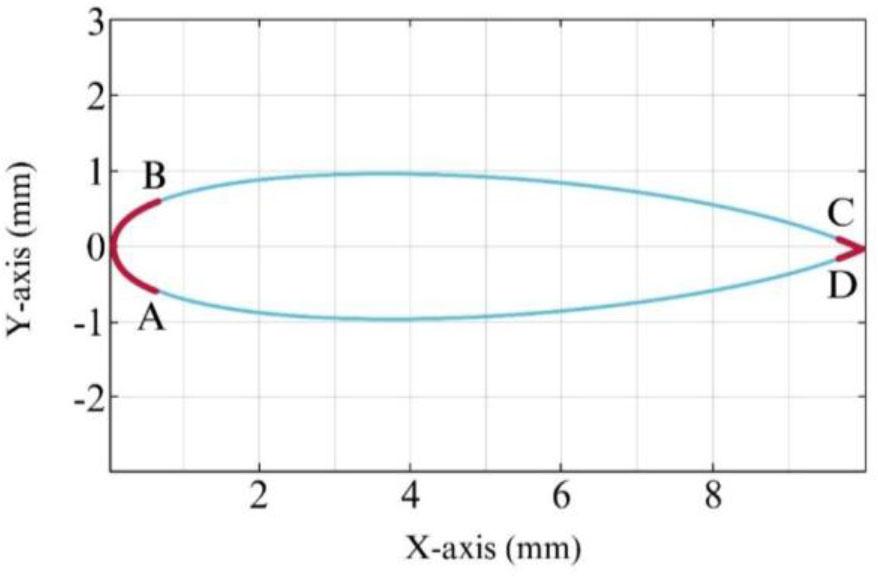
NURBS curve related to the airfoil profile [75] NACA2415 (Axes show the toolpath coordinates in the XY plane: X-axis (mm) and Y-axis (mm).
The Taylor series interpolation of the NURBS curve inevitably produces errors and feed rate abnormalities. These undesirable fluctuations reduce the accuracy of following the path and the quality of the surface. However, the PH curves offer the possibility of solving the integral equation of the interpolation analytically, allowing the interpolation equation to be determined accurately [40]. The sharp NURBS curve corners can be approximated using PH curves inorder to reduce feed rate variations.
The first-order Hermitian information associated with the position area and the slope at the beginning and end points must be derived from the complex representation of a two-dimensional PH curve in order to approximate a NURBS curve with a fifth-degree PH curve [76], [77].
Here, the real parameter ξ is a complex polynomial in the form w(ξ) = u(ξ) + iv(ξ) by definition. It can be that:
If d1 and d0, r1, r0 are respectively the complex representation of the initial point, the endpoint, the initial slope and the end slope in the PH curve, w(ξ) is defined as follows using Bernstein [76]:
To reduce the difference between the generated and original NURBS curves, the acute angle PH curve must be created. We calculate the root mean square error between two curves. If this value exceeds the threshold, the acute angle area on the main curve is divided into two segments with PH curves. This is repeated until the error value is acceptable. To apply this approach to the airfoil in Fig. 1, use a root mean square value of e = 1μm. In Table 1, dividing the acute corner area affects the difference between the original and the generated PH curve.
Profile airfoil PH curve error comparison.
| Error [µm] | ||||
| Curve area | No area division | Division by area | ||
| Base mean square | Max | Base mean square | Max | |
| AB | 4.9193 | 13.43 | 0.5025 | 1.43 |
| CD | 4.3792 | 9.78 | 0.5462 | 1.45 |
The speed profiling section first calculates the sharp corner forward speed. For this purpose, two methods of speed profile determination to limit the vector error [47] and speed profile determination based on the curvature [48] are combined to determine the feed rate in the following equation used for the corners:
In (22), the values Vaf(uk) and Vcf(uk) are obtained in the following form:
In (23) and (24), Vaf, Vcf and Vmax represent the feed rate based on chord error, the feed rate based on curvature, and the input feed rate, respectively. δ and κ represent the NURBS curve chord tolerance and curvature.
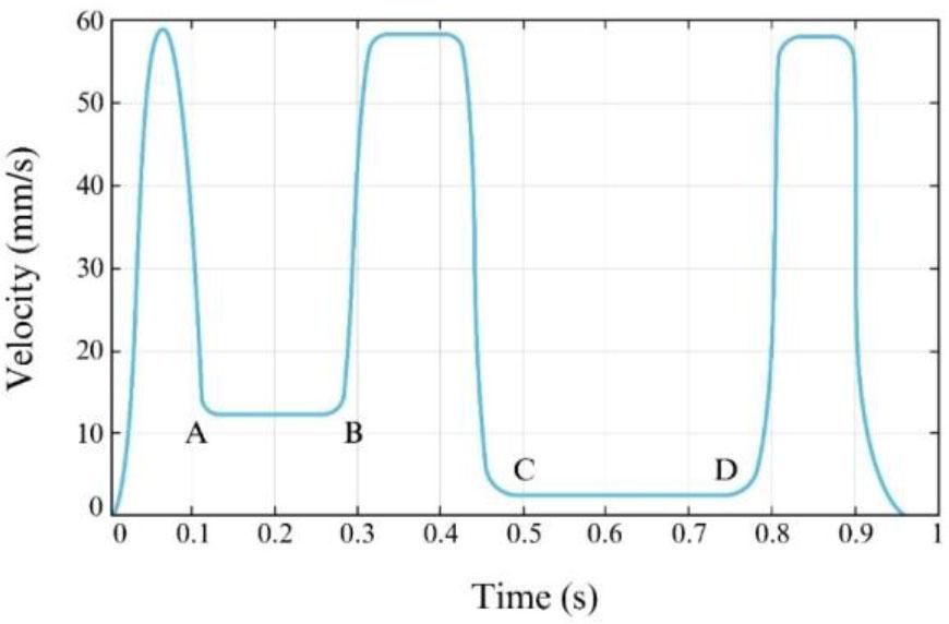
After defining the sharp corners, the profile of the advancing speed on the airfoil creates the PH curve and the speed profile.
The dynamic diagnosis section of the first three sections is mandatory. It does not comply with the condition of the maximum error of following the path because, in these sections, the error of following the desired path was not considered. To predict the path following error, the servo control system should be modeled and simulated for each axis. The block diagram in Fig. 3 is a dynamic model of the servo control system.
To calculate the servo control system's closed-loop conversion function in Fig. 3:

Servo control system block diagram [16].
The parameters of (25) are specified in Table 2.
Servo control system transformation function parameters [16].
| Parameter | X axis | Y axis |
|---|---|---|
| a0 | 1.938 × 10⁹ | 1.904 × 10⁹ |
| a1 | 3.538 × 10⁷ | 3.496 × 10⁷ |
| a2 | 2.135 × 10⁵ | 2.120 × 10⁵ |
| a3 | 6.984 × 10² | 6.948 × 10² |
| a4 | 1.00 | 1.00 |
| b0 | 1.938 × 10⁹ | 1.904 × 10⁹ |
| b1 | 3.476 × 10⁷ | 3.435 × 10⁷ |
| b2 | 1.471 × 10⁵ | 1.466 × 10⁵ |
According to (25), the conversion function over the inaccuracy on each axis E(s) and the speed on each axis V(s) is obtained as follows:
By calculating the error on each axis, the following error routing is achieved [16]:
In (29), Ex and Ey are the error on the x-axis and the y-axis, respectively. ϕ is the angle between the tangent to the tool path and the x-axis. The dynamic detection section uses (28) and (29) to calculate the path following error. Suppose the path following error ɛe exceeds the maximum path following error ɛmax. In this case, the calculation operation is stopped and the progress is saved at that moment V(uk). The speed profile is then created again while the maximum forward speed value is set to V(uk). This process continues until the path following the error is within the allowable range. Fig. 4 illustrates the airfoil speed profile from a PH-based forward-looking algorithm. As can be seen in this figure, the maximum forward speed in the BC part of the curve has been reduced compared to Fig. 2, so that the amount of the path following error in this range does not exceed its permissible limit.
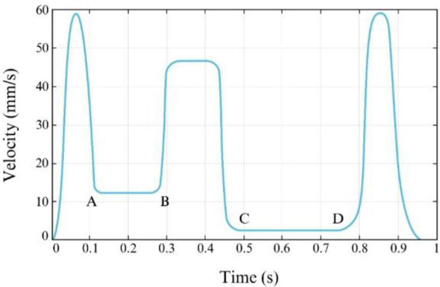
Forward speed profile on an airfoil using a PH-based predictive algorithm.
To ensure the clarity of the mathematical formulation presented below, key parameters and their operational meanings in CNC systems are summarized in Table 3.
Summary of key mathematical parameters and control variables used in the predictive interpolation algorithm, including their physical meaning and relevance to CNC machining operations.
| Symbol | Description | Unit | Relevance in CNC operation |
|---|---|---|---|
| Ts | Sampling period | s | Defines time resolution for interpolator output |
| Vk | Feed rate at step k | mm/s | Instantaneous tool motion speed |
| Ak | Acceleration at step k | mm/s2 | Dynamic response of tool motion |
| δ | Chord error tolerance | mm | Maximum deviation from ideal path for profile generation |
| κ(u) | Scalar curvature | mm−1 | Describes path sharpness, used for adaptive feed rate |
| kth | Curvature threshold | mm−1 | Defines boundary to detect sharp corners |
| Amax | Maximum allowable acceleration | mm/s2 | Mechanical limit of CNC axis acceleration |
| Vmax | Maximum allowable feed rate | mm/s | Cap of commanded feed velocity |
| Δs | Arc-length step per interpolation | mm | Tool travel distance per cycle |
| L | Lookahead arc window | mm | Used for predicting upcoming curvature transitions |
| ɛe | Path-following error | mm | Actual deviation from commanded path |
| ϕ | Tangent angle of toolpath | rad | Used for transforming Cartesian error into tangential form |
This section describes a predictive module that is integrated into the interpolation algorithm to improve performance under variable curvature and real-time constraints. The module adjusts the feed rate according to the local curvature and a lookahead strategy to prevent excessive deceleration or velocity spikes and ensure smooth motion with bounded acceleration and chord error.
Let the interpolated curve be defined as a parametric PH-NURBS curve:
Let:
C′(u) and C″(u) be the first and second derivatives of the curve,
κ(u) be the scalar curvature at parameter uuu,
V(u) be the adaptive feed rate for the parameter uuu,
amax be the maximum allowable tangential acceleration,
Δs be the arc length per interpolation step.
Curvature is calculated as:
Since the curve is represented by the PH formulation, both derivatives are analytically available.
To prevent excessive acceleration during curve transitions, define a curvature-based upper limit for the feed rate:
ɛ is a small constant (10−6) to avoid division by zero,
Vmax is the global maximum feed rate.
To handle abrupt curvature changes smoothly, apply a predictive lookahead over an arc window L:
Then:
This smoothes the profile and avoids reactive deceleration. Using the adaptive feed rate V(u), estimate time increment:
Update the curve parameter using the arc-length derivative:
The predictive curvature-based feed rate adjustment module requires several input parameters to ensure both numerical stability and dynamic safety in real-time CNC operations. These parameters are summarized in Table 4. Their selection has a direct influence on the responsiveness, smoothness, and accuracy of the interpolated toolpath. A reasonable tuning of these parameters allows the algorithm to effectively adapt to curvature variations while maintaining bounded acceleration and consistent motion quality.
Predictive interpolation parameter definitions.
| Parameter | Description | Value / range | Unit |
|---|---|---|---|
| amax | Maximum allowable tangential acceleration | 2 | m/s2 |
| Vmax | Maximum allowable feed rate | 1 | m/s |
| ɛ | Small positive constant to prevent division by zero in curvature-based calculations | 10−6 | |
| Δs | Arc-length step per interpolation cycle | 0.05 – 0.2 | mm |
| L | Lookahead arc length used for predictive curvature filtering | 5 – 10 | mm |
All interpolation parameters used in the proposed algorithm can be directly mapped to physical control variables commonly available in industrial CNC controllers. For example, the adaptive feed rate V(u) corresponds to the real-time feed rate command, while the maximum tangential acceleration Amax reflects the acceleration limits defined by the machine servo specifications. The arc-length increment Δs represents the physical displacement of the tool per interpolation cycle, and the curvature κ(u) is inherently related to the toolpath geometry. The lookahead length L emulates advanced control strategies in modern CNC systems that pre-process upcoming segments to mitigate jerk or overshoot. Therefore, all algorithmic parameters are physically meaningful and match the established control capabilities of commercial CNC systems, ensuring compatibility and straightforward implementation.
The algorithm was developed with modularity and real-time constraints in mind to ensure its applicability on a wide range of industrial CNC platforms. All calculations are based on standard kinematic parameters and interpolation logic that are compatible with the G-code execution framework and servo control architecture commonly found in modern CNC machines. Furthermore, the algorithm does not requires any specialized hardware and has been validated with an X–Y table driven by commercially available servo drives and motion controllers. This makes the proposed interpolation scheme both scalable and transferable to various industrial machining environments, including 3-axis and 5-axis systems, with minimal integration overhead.
This section presents the numerical simulation and experimental evaluation of the interpolation algorithm applied to an airfoil profile at three toolpath orientations: 0°, 45°, and −45°, as shown in Fig. 5. These test angles cause varying dynamic responses along the x and y axes due to the system's anisotropic behavior. By applying the proposed interpolation method in different directions, we can evaluate its robustness under diverse dynamic conditions.
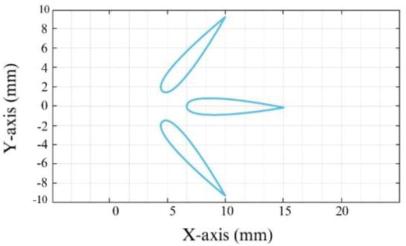
Planar toolpath coordinates, X-axis and Y-axis (mm), of the airfoil profile at three orientations (0°, 45°, and −45°), used to evaluate the predictive PH-based interpolation algorithm under varying dynamic conditions.
The simulation and tests aim to evaluate the performance of the improved algorithm including its predictive, curvature-adaptive feed rate control in maintaining path accuracy and smooth motion across these directional shifts. The input parameters used in both the simulation and the experiment are listed in Table 5. These values were selected to represent typical high-speed, high-precision machining scenarios where the benefits of predictive feed rate adaptation can be effectively observed.
Simulation and experimental input parameters for evaluating the feed rate-adaptive predictive PH interpolation algorithm.
| Symbol | Description | Value | Unit |
|---|---|---|---|
| Vmax | Maximum feed rate | 3500 | mm/min |
| Amax | Maximum acceleration | 2450 | mm/s2 |
| Jmax | Maximum jerk | 5 × 10⁴ | mm/s3 |
| δ | Lateral error limit | 1.0 | µm |
|
| Reference curve | 1.0 | mm−1 |
| εmax | Path following error limit | 15.0 | µm |
| e | Approximate curve error limit | 1.0 | µm |
A numerical simulation was performed to compare the performance of three advanced feed rate determination algorithms:
String error-limited interpolation [47],
Curvature-based feed rate control [48],
The proposed predictive interpolation algorithm based on PH curves.
As shown in Fig. 3, the simulation includes a realistic servo system model to evaluate how each algorithm handles geometric constraints and motion errors. The comparative results of the three interpolation methods, including their ability to maintain feed rate, limit geometric deviation and suppress acceleration spikes, are summarized in Table 6.
Performance comparison of interpolation algorithms.
| Interpolation algorithm | Chord error-limited [47] | Curvature-based feed rate [48] | PH-based predictive interpolator | ||
|---|---|---|---|---|---|
| Error on each axis [µm] | X axis | MAX | 357.68 | 194.77 | 56.96 |
| Root mean square | 75.65 | 41.53 | 20.30 | ||
| Y axis | MAX | 132.55 | 22.64 | 13.97 | |
| Root mean square | 26.32 | 8.41 | 3.54 | ||
| Routing error [µm] | MAX | 14.11 | 47.12 | 142.79 | |
| Root mean square | 35.14 | 12.98 | 3.84 | ||
| MIN | 16.780 | 8.51 | 2.32 | ||
| Time [s] | 0.3431 | 0.4526 | 0.3440 | ||
Table 6 shows that the proposed predictive interpolation algorithm based on PH curves has significantly lower error values compared to the chord error-limited and curvature-based interpolation methods. By proactively detecting sharp corners and reducing the feed rate in high-curvature regions, the algorithm effectively minimizes the interpolation error and improves the path-tracking accuracy. In addition, by predicting the system's dynamic behavior, the algorithm adjusts the feed rate profile in advance to maintain optimal path-following performance under varying machining conditions.
Fig. 6 illustrates the feed rate profiles generated by the three algorithms. The PH-based predictive method produces a much smoother speed trajectory, due to its ability to anticipate geometric variations along the path. In contrast, the chord error-limited and curvature-based methods exhibit abrupt changes in feed rate due to their lack of predictive capability. These reactive adjustments result in less stable motion and higher acceleration peaks, which can compromise machining quality. The smoothness of the PH-based feed rate profile not only improves mechanical performance, but also contributes to a more consistent surface finish.
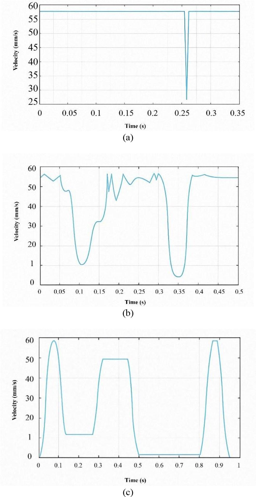
Comparison of velocity profiles: (a) Forward velocity determination algorithm to limit the chord error. (b) Forward velocity determination algorithm based on curvature. (c) Prediction algorithm based on PH.
Fig. 7 compares the path-following error of the three investigated interpolation algorithms. The proposed PH-based predictive algorithm has a much lower tracking error than the chord error-limited and curvature-based methods. This improvement stems from the predictive module's ability to estimate the system’s dynamic response and proactively adjust the feed rate to keep the error within a predefined allowable range.
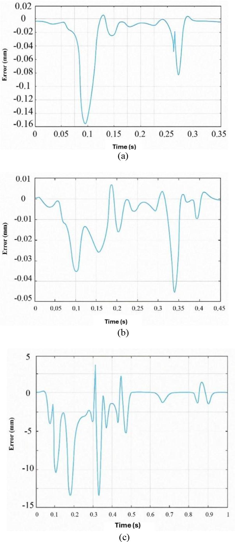
Comparison of trajectory-tracking error: (a) Forward speed algorithm to limit string error; (b) Forward speed algorithm based on curvature; (c) PH-based forward-looking algorithm.
In contrast, the other two algorithms have no mechanism for directly limiting the path-following error. Their feed rate decisions are based solely on geometric factors such as string error or curvature without considering system dynamics, resulting in greater deviations from the reference path, especially in high-curvature regions.
Specifically, in the BC segment of the trajectory, the proposed algorithm reduces the feed rate in anticipation of an increased curvature and a potential tracking error. This adjustment ensures that the error does not exceed the allowed threshold of 15 μm. The simulation confirms that this predictive correction mechanism effectively limits the tracking error and provides both accuracy and reliability in dynamic machining environments.
The numerical simulation results for the airfoil profile at three different trajectory angles (0°, 45°, and −45°) are summarized in Table 7. Although the tracking error on each individual axis (X and Y) varies depending on the direction of motion and the corresponding system dynamics, the total path-following error remains consistently within acceptable limits across all test cases.
Airfoil curve numerical simulation at three angles.
| Interpolation algorithm | 0° | –45° | 45° | ||
|---|---|---|---|---|---|
| Error on each axis [µm] | X axis | MAX | 57.97 | 43.51 | 38.71 |
| Root mean square | 20.30 | 14.93 | 14.19 | ||
| Y axis | MAX | 13.98 | 38.85 | 43.66 | |
| Root mean square | 3.56 | 14.24 | 14.99 | ||
| Routing error [µm] | MAX | 14.11 | 14.11 | 14.12 | |
| Root mean square | 35.14 | 3.84 | 3.84 | ||
| MIN | 16.780 | 2.31 | 2.31 | ||
This consistency proves the robustness of the proposed PH-based predictive interpolation algorithm. By dynamically simulating the system's response and adjusting the feed rate in advance, the algorithm successfully ensures that the path-following error remains below the defined threshold, regardless of directional variations. The results confirm the algorithm’s ability to maintain high-precision performance even under varying dynamic conditions.
The proposed interpolation algorithm was experimentally validated on an X–Y positioning table driven by two AC servo motors, as shown in Fig. 8. Each motor is equipped with an encoder with a resolution of 2500 pulses per revolution. The algorithm is implemented on a host computer that communicates with the servo system via a custom-designed motion control card. This card uses bit-pattern interpolation [80] to manage the high-precision motor control in real time.
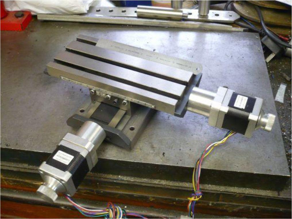
Experiment hardware.
To accurately evaluate the path-following performance, two digital linear rulers with a resolution of 1 μm are mounted along the X and Y axes of the table. These rulers provide precise position feedback, enabling error analysis during toolpath execution. The interpolation algorithms were developed and executed using the MATLAB and Visual Basic.NET software environments. This hardware setup approximates standard industrial CNC configurations and enables the direct applicability of the proposed algorithm in real-world precision machining scenarios. The use of TECO servo components and CARMAR digital scales reflects components commonly found in high-end X–Y stages and milling platforms. This ensures that the experimental results are representative of the industrial performance benchmarks listed in Table 8.
Hardware specifications used in the experiment.
| Item | Description | Application in industry | Reason for selection |
|---|---|---|---|
| Servo drive | AC servo drive TECO TSTA-20C | Commonly used in CNC machine tools for high-speed, closed-loop motor control | Provides stable torque-speed characteristics and is compatible with standard motion controllers |
| Servo motors | TECO TST0640 / TSB0845 AC servo motors | Widely implemented in industrial X–Y stages and CNC milling systems | High positioning accuracy, low latency response, and encoder feedback support |
| Motion controller | PCI-1240 motion control card | Used in precision motion control applications including real-time CNC path tracking | Offers deterministic motion planning and is compatible with bit-pattern interpolation |
| Digital linear scales | CARMAR high-resolution linear scales (1 µm resolution) | Commonly used in coordinate measuring machines (CMMs) and precision CNC tables | Provides reliable high-resolution feedback for path-following error evaluation |
The airfoil curve experiments were performed at an inlet feed rate of 3500 mm/min as shown in Fig. 5. Path-following errors were measured for three different interpolation algorithms: the string error-limited feed rate method [47], the curvature-based feed rate method [48], and the proposed predictive PH-based interpolation algorithm shown in Fig. 9.
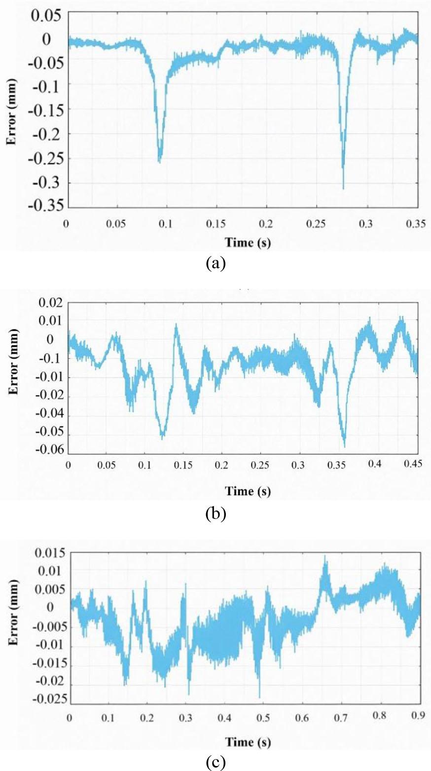
Comparison of the path-following error when testing interpolation algorithms (a) Algorithm for determining the feed rate to limit the error and tri (b) Algorithm for determining the feed rate based on the curvature; (c) PH-based predictive algorithm.
The experimental results confirm that the proposed algorithm significantly improves the path-tracking performance, especially in regions with sharp curvature. Unlike the other two methods, which exhibit noticeable tracking deviations for tight turns, the predictive algorithm adaptively reduces the feed rate in these regions based on the curvature and system dynamics, keeping the path-following error within the allowable limits.
Table 9 shows the experimental machining accuracy obtained with the proposed PH-based predictive interpolation algorithm on the X–Y CNC table. The results show that the maximum path-following error remained within the allowable limit of 15 μm in all tested directions. The RMS error values of 20.25 μm and 14.85 μm for the X and Y axes, respectively, confirm the algorithm’s ability to ensure smooth and accurate tool motion under dynamic conditions. The minimum observed error of 2.31 μm corresponds to the resolution limit of the digital linear rulers used in the setup. Importantly, the combined path deviation did not exceed 14.10 μm even in high-curvature regions, verifying the effectiveness of curvature-based predictive feed rate control in limiting dynamic deviation. These real-world machining results are consistent with the simulation results and emphasize the robustness and practical applicability of the proposed method.
Experimental machining accuracy using PH-based predictive interpolation.
| Metric | X axis [µm] | Y axis [µm] | Combined error [µm] |
|---|---|---|---|
| Maximum path-following error | 57.85 | 43.62 | 14.10 |
| RMS path-following error | 20.25 | 14.85 | 3.84 |
| Minimum error observed | 2.31 | 2.31 | 2.31 |
| Average deviation from reference trajectory | 18.21 | 13.74 | — |
| Machining tolerance achieved (from ruler data) | ±15 | ±15 | Within allowed range |
The proposed feed rate-adaptive predictive interpolation algorithm showed consistent path-following accuracy under both simulated and real-world machining conditions. Nevertheless, slight discrepancies were found between the numerical simulation results and the experimental results, particularly in the maximum path-following error metrics along the X and Y axes (see Table 7 and Table 9).
These discrepancies are primarily attributed to unmodeled physical phenomena in the experimental setup, including:
Servo lag and backlash in mechanical transmission components.
Encoder resolution limitations and quantization noise.
Temperature-induced drift and material compliance.
Real-time computational delays are not reflected in the simulation models.
Despite these real-world limitations, the experimental results closely aligned with the numerical predictions. This shows that the proposed algorithm is robust against hardware imperfections and can be adapted to the actual machine dynamics. The RMS and the maximum path-following errors remained within the industrial machining tolerance of ±15 μm.
From an industrial application perspective, the PH-based predictive interpolation algorithm offers several advantages:
Enhanced motion smoothness and surface quality due to curvature-aware feed rate adjustment.
Predictive error suppression increases precision, even for high-curvature toolpaths, which are prevalent in aerospace and die/mold manufacturing.
The algorithm’s compatibility with standard motion controllers (PCI-1240) and servo drives confirms its potential for direct integration into commercial CNC platforms.
To better contextualize the results, Table 10 provides a comparative summary of the path-tracking performance and feed rate control features of this study in comparison to other notable methods in the literature.
Comparative analysis of the feed rate interpolation algorithms in literature.
| Study | Interpolation method | Max path error [µm] | RMS error [µm] | Feed rate adaptivity | Predictive control | Industrial suitability |
|---|---|---|---|---|---|---|
| [47] | Chord error-limited | 357.68 (X) / 132.55 (Y) | 75.65 / 26.32 | ✗ | ✗ | Limited |
| [48] | Curvature-based | 194.77 (X) / 22.64 (Y) | 41.53 / 8.41 | ✓ | ✗ | Moderate |
| [78], [79] | Jerk-limited cubic spline | 65 – 120 (AVG) | 22 – 30 | ✓ | ✗ | Moderate |
| [11], [14] | Real-time PH interpolation | ∼60 – 100 | N/A | ✓ | Partial | High |
| This study | PH-based predictive | 57.85 (X) / 43.62 (Y) | 20.25 / 14.85 | ✓ | ✓ | High |
This paper presents a novel predictive interpolation algorithm that combines NURBS and PH curve representations, tailored for high-speed and high-precision CNC machining. The proposed method improves conventional interpolation strategies by integrating sharp corner detection, PH-based geometric smoothing, and a curvature-adaptive feed rate adjustment mechanism based on dynamic prediction. By incorporating a lookahead strategy and real-time error modeling, the algorithm successfully maintains smooth, bounded-acceleration velocity profiles while minimizing path-following errors, even in high-curvature regions.
The algorithm has been rigorously validated through both numerical simulations and physical experiments using a dual-axis CNC positioning platform. The results show significant improvements over conventional curvature-based and chord error-limited interpolators, with significant reductions in RMS and peak tracking errors, particularly under dynamically varying feed rate conditions. Furthermore, the method achieves real-time feasibility with competitive execution times, confirming its suitability for integration into industrial CNC control systems.
However, several limitations of the current study must be acknowledged. First, the algorithm was tested on a dual-axis motion platform. Although the principles are theoretically extensible, the performance in multi-axis (5-axis) CNC systems remains to be investigated. Second, the experimental validation was performed with a customized motion controller and software environment, which may limit direct generalizability to commercial CNC controllers without adaptation. In addition, the algorithm currently assumes ideal encoder feedback and overlooks factors such as backlash, thermal drift, and tool wear that may affect accuracy in real-world production.
Future research can address these limitations by extending the algorithm to multi-axis CNC systems with synchronized motion coordination, as well as by evaluating performance under real industrial machining conditions that involve cutting forces, thermal effects, and actuator saturation. The integration of machine learning techniques for adaptive parameter tuning or incorporating online disturbance estimation could further improve the robustness and autonomy of the interpolation process. In addition, embedding the algorithm in commercial CNC firmware or FPGA-based hardware platforms would facilitate its transition from prototype to practical use.
Ultimately, the proposed PH-based predictive interpolation algorithm provides a robust and practical solution for modern CNC machining that balances computational efficiency, motion smoothness, and geometric accuracy. Its predictive capabilities, combined with curvature-aware control, provide a promising foundation for the next-generation of high-speed machining systems.