
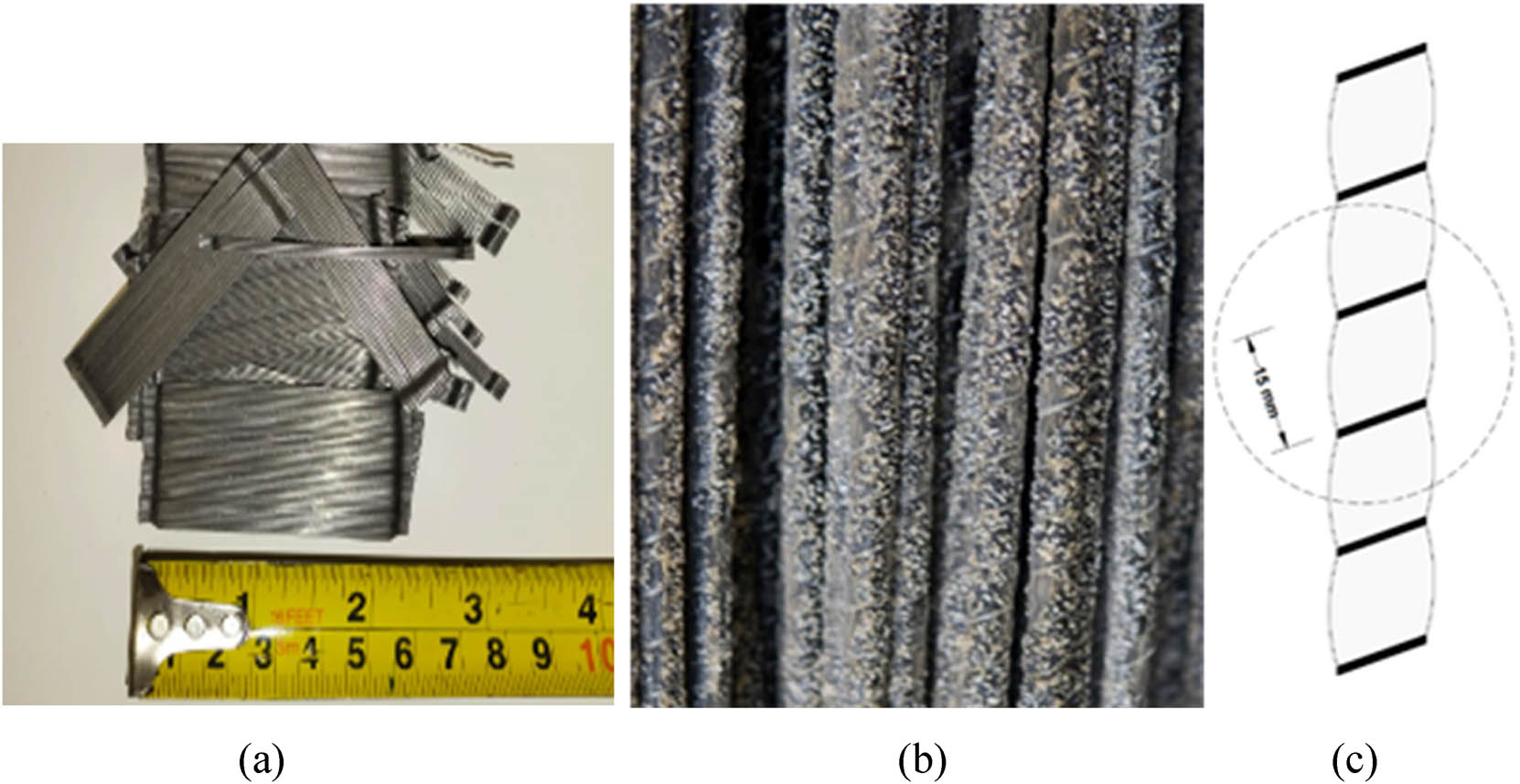
Figure 1
(a) Steel fibers; (b) BFRP rebars used in the study; and (c) BFRP rebar's surface profile.
Table 1
Compressive and splitting tensile strengths of concrete at ambient and elevated temperature.
| Concrete type | Compressive strength (MPa) | Splitting tensile strength (MPa) | ||
|---|---|---|---|---|
| Ambient temperature | 200 °C | Ambient temperature | 200 °C | |
| PC | 42.0 ± 2.8 | 41.4 ± 3.2 | 3.8 ± 0.2 | 3.7 ± 0.3 |
| FRC | 46.0 ± 3.1 | 45.2 ± 3.3 | 6.0± 0.5 | 5.8 ± 0.6 |
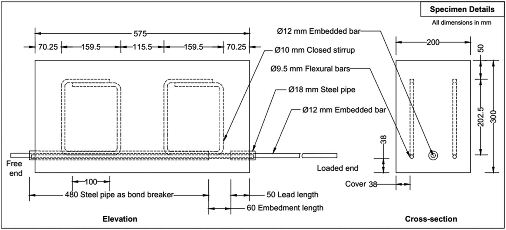
Figure 2
Beam-end test specimen details (all dimensions are in mm).
Table 2
Test matrix.
| S. No. | Specimen ID | Volume fraction of steel fibers | Type of test rebar | Diameter of rebar (mm) | Exposure temperature | No. of test specimens |
| 1 | PCSB-A | 0 | Steel | 12 | Ambient temperature | 2 |
| 2 | PCSB-100 | 0 | Steel | 12 | 100°C | 2 |
| 3 | PCSB-200 | 0 | Steel | 12 | 200°C | 2 |
| 4 | FRCSB-A | 1% | Steel | 12 | Ambient temperature | 2 |
| 5 | FRCSB-100 | 1% | Steel | 12 | 100°C | 2 |
| 6 | FRCSB-200 | 1% | Steel | 12 | 200°C | 2 |
| 7 | PCBB-A | 0 | BFRP | 12 | Ambient temperature | 2 |
| 8 | PCBB-100 | 0 | BFRP | 12 | 100°C | 2 |
| 9 | PCBB-200 | 0 | BFRP | 12 | 200°C | 2 |
| 10 | FRCBB-A | 1% | BFRP | 12 | Ambient temperature | 2 |
| 11 | FRCBB-100 | 1% | BFRP | 12 | 100°C | 2 |
| 12 | FRCBB-200 | 1% | BFRP | 12 | 200°C | 2 |
| Total = 24 | ||||||
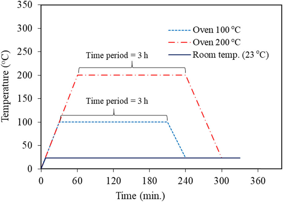
Figure 3
Temperature–time variation followed in heating and cooling.
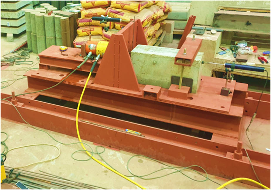
Figure 4
Setup for testing beam end specimens.
Table 3
Summary of study results.
| Specimen ID | Peak force (kN) | Average bond strength (MPa) | Slip at peak load (mm) | Residual bond stress (MPa) | Failure mode* |
|---|---|---|---|---|---|
| PCSB-A | 43.9 ± 2.40 | 19.3 ± 1.05 | 2.895 ± 0.12 | 2.9 ± 0.14 | P & S |
| PCSB-100 | 42.8 ± 2.91 | 18.9 ± 1.29 | 3.200 ± 0.13 | 2.3 ± 0.16 | P & S |
| PCSB-200 | 32.5 ± 1.84 | 14.4 ± 0.81 | 3.445 ± 0.15 | 7.9 ± 0.54 | P & S |
| FRCSB-A | 40.4 ± 2.51 | 17.9 ± 1.11 | 1.540 ± 0.1 | 3.6 ± 0.28 | P |
| FRCSB-100 | 39.3 ± 3.10 | 17.4 ± 1.37 | 1.615 ± 0.12 | 4.4 ± 0.28 | P |
| FRCSB-200 | 32.9 ± 2.37 | 14.5 ± 1.05 | 2.835 ± 0.24 | 4.4 ± 0.35 | P |
| PCBB-A | 37.5 ± 1.58 | 16.6 ± 0.7 | 1.955 ± 0.09 | 5.0 ± 0.28 | P & S |
| PCBB-100 | 41.7 ± 2.42 | 18.4 ± 1.07 | 2.735 ± 0.15 | 1.8 ± 0.13 | P & S |
| PCBB-200 | 40.7 ± 2.46 | 18.0 ± 1.09 | 2.865 ± 0.19 | 3.2 ± 0.28 | P & S |
| FRCBB-A | 32.9 ± 2.13 | 14.5 ± 0.94 | 1.630 ± 0.08 | 3.6 ± 0.25 | P |
| FRCBB-100 | 40.7 ± 3.34 | 18.0 ± 1.48 | 2.295 ± 0.12 | 8.7 ± 0.64 | P |
| FRCBB-200 | 38.5 ± 3.02 | 17.0 ± 1.34 | 1.935 ± 0.13 | 9.5 ± 0.78 | P & S |
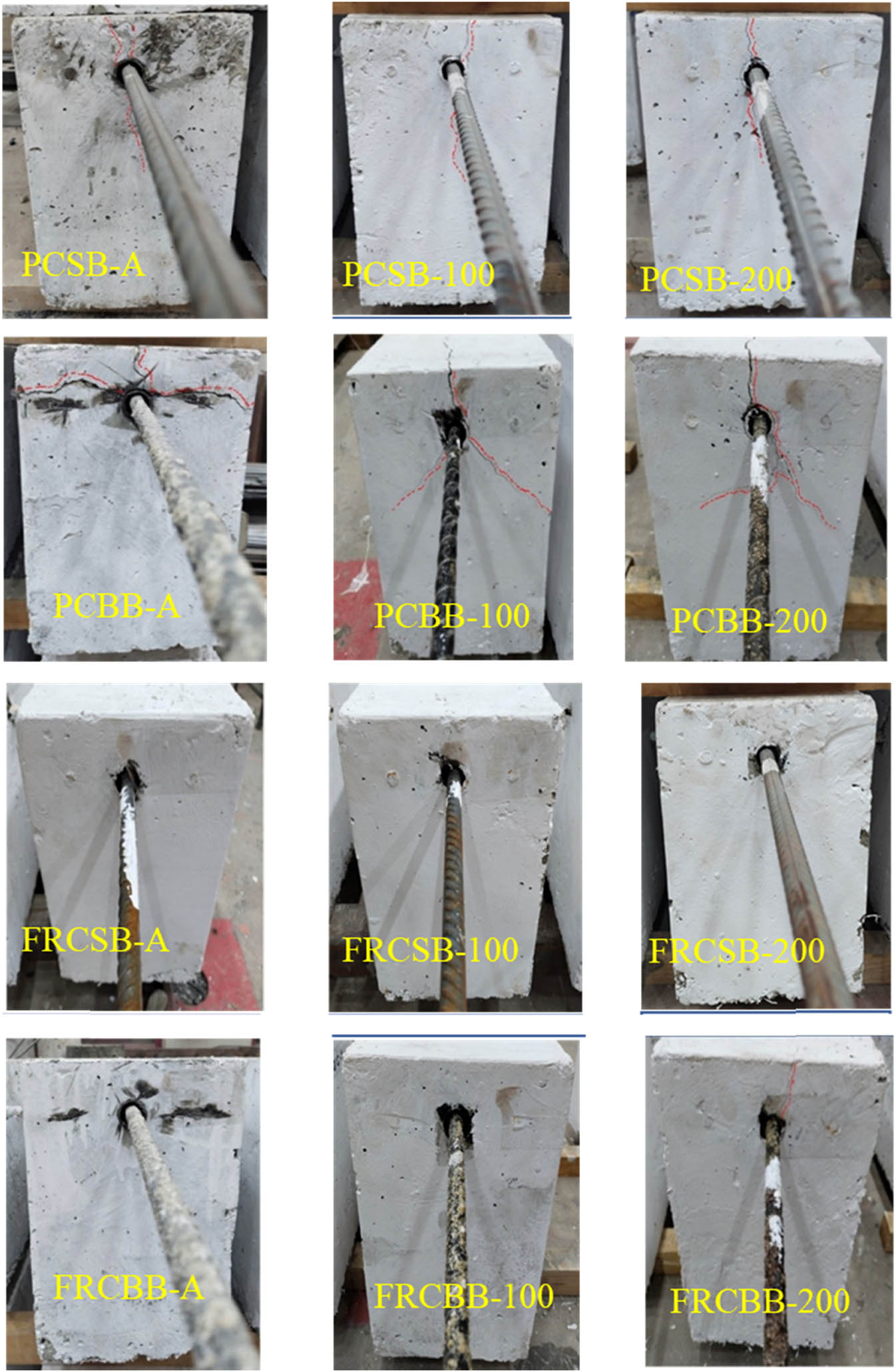
Figure 5
Failure modes of rebars embedded in PC and FRC.
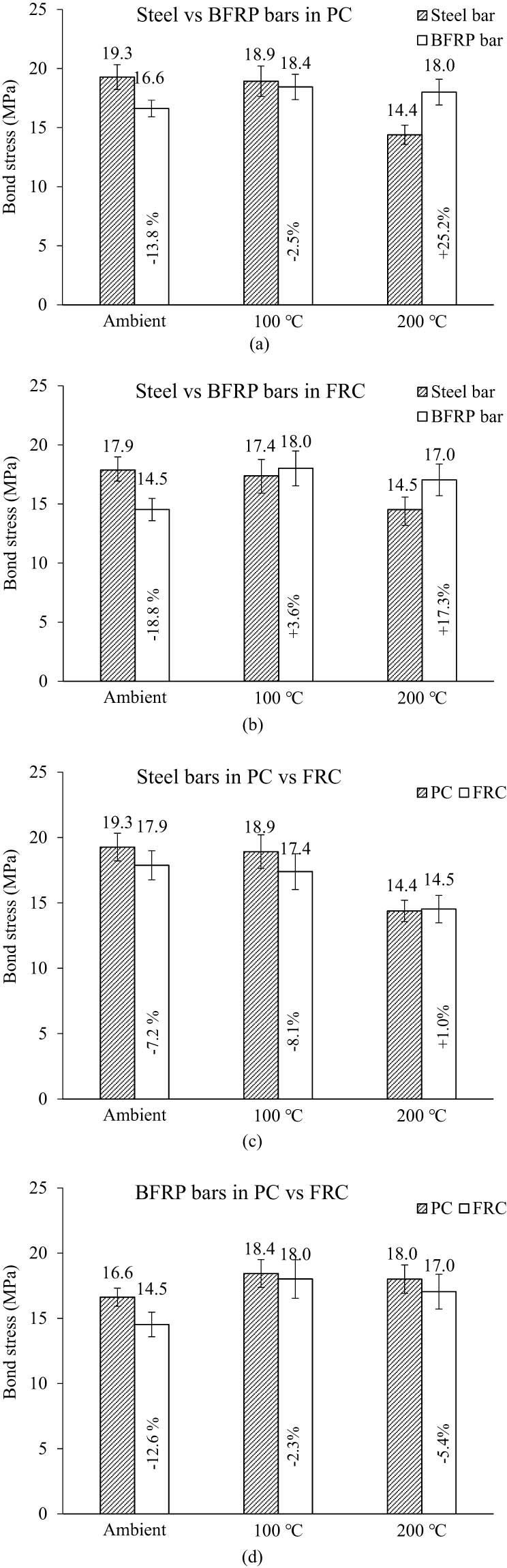
Figure 6
Comparison of bond strength of rebars embedded in PC and FRC after exposure to different temperatures: (a) steel vs BFRP bars in PC; (b) steel vs BFRP bars in FRC; (c) steel bars in PC vs FRC; and (d) BFRP bars in PC vs FRC.
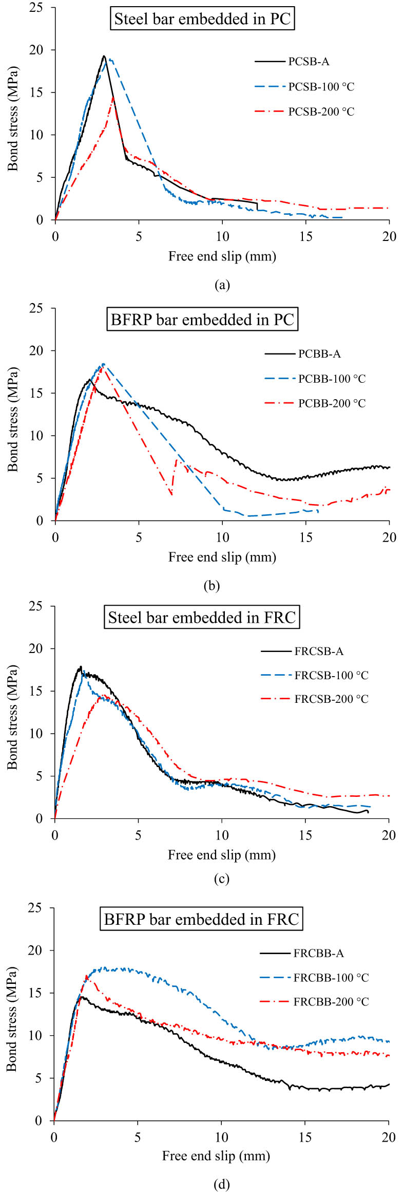
Figure 7
Bond stress–slip curves of steel and BFRP rebars embedded in PC and FRC after exposure to different temperatures: (a) steel bar embedded in PC; (b) BFRP bar embedded in PC; (c) steel bar embedded in FRC; and (d) BFRP bar embedded in FRC.
Table 4
mBPE model parameters obtained by curve fitting.
| Concrete type | Rebar type | Exposure temperature | Model parameters | |||
|---|---|---|---|---|---|---|
| s max | ||||||
| PC | Steel rebar | Ambient temperature | 0.88 | 1.500 | 0.15 | 2.895 |
| 100°C | 0.91 | 0.750 | 0.12 | 3.200 | ||
| 200°C | 0.96 | 2.300 | 0.55 | 3.445 | ||
| BFRP rebar | Ambient temperature | 0.69 | 0.124 | 0.300 | 1.955 | |
| 100°C | 0.72 | 0.340 | 0.100 | 2.735 | ||
| 200°C | 0.85 | 0.550 | 0.18 | 2.865 | ||
| FRC | Steel rebar | Ambient temperature | 0.55 | 0.190 | 0.20 | 1.540 |
| 100°C | 0.62 | 0.205 | 0.25 | 1.615 | ||
| 200°C | 0.72 | 0.380 | 0.30 | 2.835 | ||
| BFRP rebar | Ambient temperature | 0.70 | 0.100 | 0.25 | 1.630 | |
| 100°C | 0.72 | 0.110 | 0.48 | 2.295 | ||
| 200°C | 0.88 | 0.105 | 0.56 | 1.935 | ||
Table 5
Equations of bond model parameters as a function of exposure temperature.
| Embedded in PC* | Embedded in FRC* |
|---|---|
| Steel rebars | |
| (R 2 = 0.99) | (R 2 = 0.99) |
| (R 2 = 1.00) | (R 2 = 1.00) |
| (R 2 = 0.98) | (R 2 = 0.86) |
| (R 2 = 0.99) | (R 2 = 0.99) |
| BFRP rebars | |
| (R 2 = 0.93) | (R 2 = 0.89) |
| (R 2 = 0.99) | (R 2 = 1.00) |
| (R 2 = 0.79) | (R 2 = 0.95) |
| (R 2 = 0.88) | (R 2 = 0.88) |
*For quadratic models, R 2 is unity, as there are only three points.
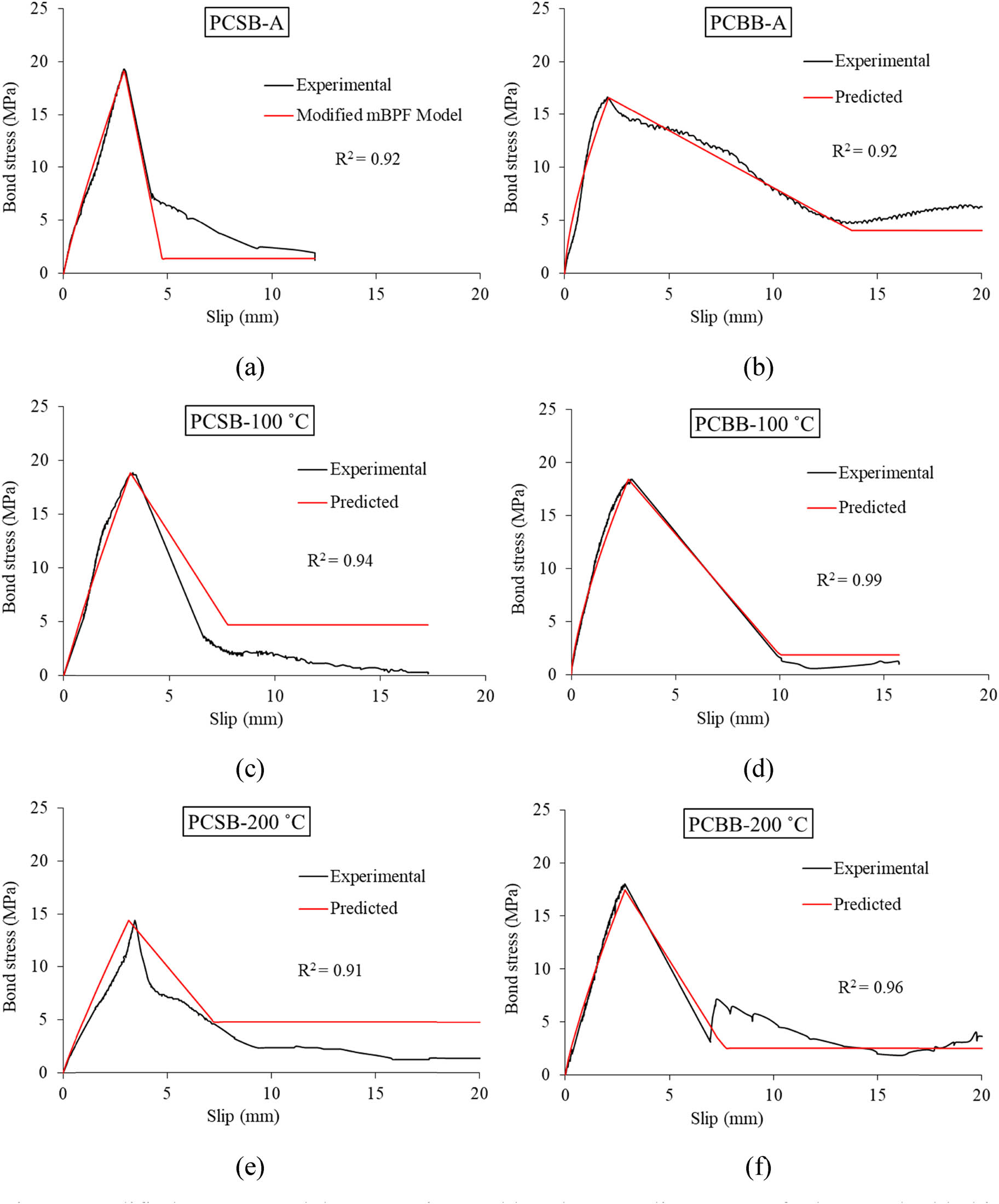
Figure 8
Modified mBPE model vs experimental bond stress–slip curves of rebars embedded in PC at ambient and elevated temperatures: (a, c, and e) steel rebars exposed to ambient temperature, 100°C, and 200°C; and (b, d, and f) BFRP rebars exposed to ambient temperature, 100°C, and 200°C.
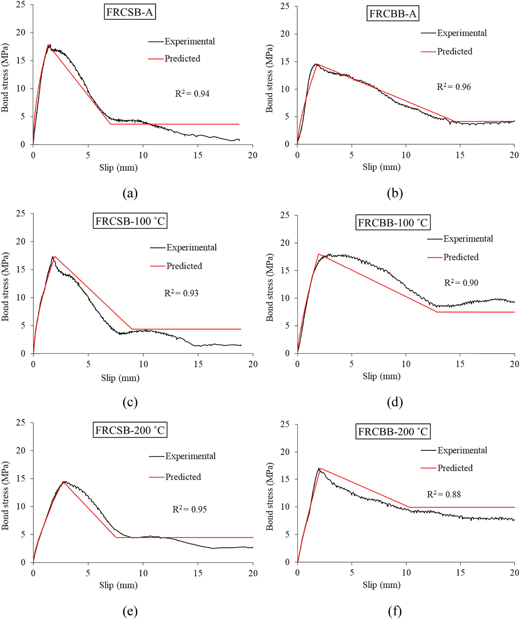
Figure 9
Modified mBPE model vs experimental bond stress–slip curves of rebars embedded in FRC at ambient and elevated temperatures: (a, c, and e) steel rebars exposed to ambient temperature, 100°C, and 200°C; and (b, d, and f) BFRP rebars exposed to ambient temperature, 100°C, and 200°C.
Table 6
Codes and researchers’ models for bond strength of steel rebars embedded in concrete*.
| Code/Researcher | Model for ambient temperature | Model for elevated temperature |
|---|---|---|
| ACI 408R-03 [26] | NA | |
| CEB-FIP Model Code [34] | NA | |
| CEB-FIP Model Code [35] | NA | |
| Huang [36] | ||
| Lublóy and György [37] |
* = bond strength at room temperature (MPa); = specified compressive strength of concrete (MPa); = diameter of rebar (mm); = bond strength at elevated temperature (MPa); T = exposure temperature (°C); NA = not available model.
Table 7
Prediction of bond strength of steel rebars using codes and researchers’ models*.
| Specimen ID | Bond strength model | |||||||||
|---|---|---|---|---|---|---|---|---|---|---|
| ACI 408R-03 [26] | CEB-FIP model code [34] | CEB-FIP model code [35] | Huang [36] | Lublóy & György [37] | ||||||
| (MPa) | (MPa) | (MPa) | (MPa) | (MPa) | ||||||
| PCSB-A | 10.80 | 0.56 | 12.96 | 0.67 | 16.20 | 0.84 | 12.96 | 0.67 | 16.20 | 0.84 |
| PCSB-100 | NA | — | NA | — | NA | — | 12.33 | 0.65 | 16.20 | 0.86 |
| PCSB-200 | NA | — | NA | — | NA | — | 11.54 | 0.80 | 16.20 | 1.13 |
| FRCSB-A | 11.3 | 0.63 | 13.56 | 0.76 | 16.96 | 0.95 | 13.56 | 0.76 | 16.96 | 0.95 |
| FRCSB-100 | NA | — | NA | — | NA | — | 12.90 | 0.74 | 16.96 | 0.97 |
| FRCSB-200 | NA | — | NA | — | NA | — | 12.07 | 0.83 | 16.96 | 1.17 |
* = predicted bond strength; = experimental bond strength; NA = not available results.
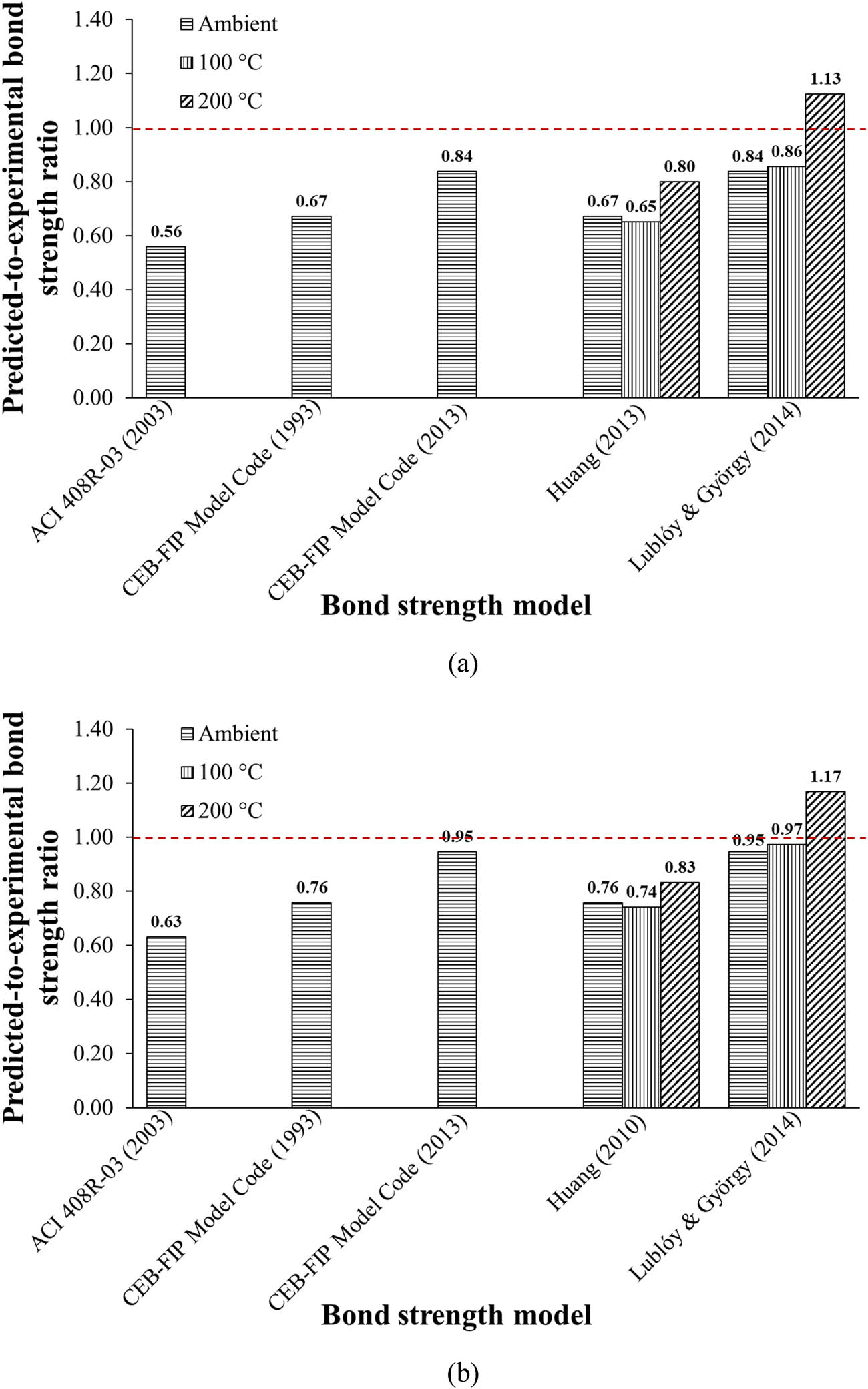
Figure 10
Comparison of predicted and experimental bond strength for: (a) steel rebars embedded in PC and (b) steel rebars embedded in FRC.
Table 8
Codes and researchers’ models for bond strength of BFRP bars embedded in concrete*.
| Code/Researcher | Model for ambient temperature | Model for elevated temperature |
|---|---|---|
| ACI 440.1R-15 [8] | NA | |
| CAN/CSA-S6-14 [11] | NA | |
| JSCE [38] | NA | |
| Model (1) – El-Gamal [39] | ||
| Model (2) – El-Gamal [39] | ||
| Özkal et al. [40] |
* = bond strength at ambient temperature (MPa); = specified compressive strength of concrete (MPa); C = smaller of the cover to the center of the BFRP rebar or 1.5 times of the center-to-center spacing of the rebars (mm) (= 44 mm used in this study); c = = diameter of rebar (mm) (= 12 mm used in this study); = embedment length of BFRP rebars (mm) (= 60 mm used in this study); d cs = smaller of distance from the closest concrete surface to the center of the BFRP rebars and 2/3 of the center-to-center spacing of the BFRP rebars (mm) (= 44 mm used in this study); k 1 = rebar location factor = 1.0; k 4 = rebar surface factor = 0.8; c = smaller of concrete cover to the BFRP rebar and 1.5 times of the rebar spacing (mm) (= 38 mm used in this study); f fu = tensile strength of BFRP rebars (MPa); = bond strength at elevated temperature (MPa); ΔT = difference between exposure temperature (T) and ambient temperature (20°C); t = exposure duration in hours (= 3 h used in this study); = bond strength of BFRP rebar at room temperature (MPa); = bond strength of steel rebar at room temperature (MPa); T = exposure temperature (°C); NA = not available model.
Table 9
Prediction of bond strength of BFRP rebars using codes and researchers’ models.
| Specimen ID | Bond strength model | |||||||||||
|---|---|---|---|---|---|---|---|---|---|---|---|---|
| ACI 440.1R-15 [8] | CAN/CSA-S6-14 [11] | JSCE [38] | Model (1) – El-Gamal [39] | Model (2) – El-Gamal [39] | Özkal et al. [40] | |||||||
| (MPa) | (MPa) | (MPa) | (MPa) | (MPa) | (MPa) | |||||||
| PCBB-A | 13.50 | 0.81 | 8.40 | 0.51 | 6.47 | 0.39 | 10.93 | 0.66 | 16.20 | 0.98 | 13.50 | 0.81 |
| PCBB-100 | NA | — | NA | — | NA | — | 8.85 | 0.48 | 14.12 | 0.77 | 11.68 | 0.63 |
| PCBB-200 | NA | — | NA | — | NA | — | 6.25 | 0.35 | 11.53 | 0.64 | 10.02 | 0.56 |
| FRCBB-A | 14.13 | 0.97 | 8.80 | 0.61 | 6.81 | 0.47 | 11.43 | 0.79 | 16.96 | 1.17 | 14.13 | 0.97 |
| FRCBB-100 | NA | — | NA | — | NA | — | 9.36 | 0.52 | 14.88 | 0.83 | 12.22 | 0.68 |
| FRCBB-200 | NA | — | NA | — | NA | — | 6.76 | 0.40 | 12.28 | 0.72 | 10.49 | 0.62 |
* = predicted bond strength; = experimental bond strength; NA = not available results.
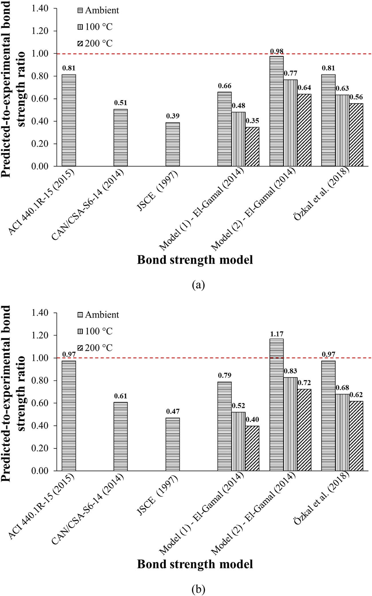
Figure 11
Comparison of predicted with experimental bond strength for: (a) BFRP rebars embedded in PC and (b) BFRP rebars embedded in FRC.