
Table 1
Parameters for different layers.
| Parameters (unit) | ITO [35] | TiO2 [36] | SnS [37] | NiO [38] |
|---|---|---|---|---|
| Thickness (µm) | 0.2 | 0.5 | 2 | 0.03–0.1 |
| Energy gap (eV) | 3.3 | 2.26 | 1.3 [39] | 3.8 |
| CBDOS (cm−3) | 5.2 × 10¹⁸ | 2 × 10¹⁷ | 7.5 × 10¹⁸ | 2.8 × 10¹⁹ |
| Dielectric constant | 8.9 | 10 | 12.5 | 10.07 |
| Hole mobility (cm2 V−1 s−1) | 10 | 25 | 4 | 56.5 |
| VBDOS (cm−3) | 1 × 10¹⁸ | 6 × 10¹⁸ | 1 × 10¹⁹ | 1 × 10¹⁹ |
| Electron mobility cm2 V−1 s−1 | 10 | 100 | 100 | 130 |
| Shallow uniform-acceptor density (cm−3) | 0 | 0 | 5.7 × 10¹⁵ | 2.8 × 10¹⁹ |
| Shallow uniform-donor density (cm−3) | 1 × 10²⁰ | 1 × 10¹⁷ | 0 | 0 |
| Electron affinity (eV) | 4.4 | 4.2 | 3.52 [40] | 1.46 |
| RRC (cm3 s−1) | 1 × 10⁻⁸ | 1 × 10⁻⁸ | 2.3 × 10⁻⁹ [41] | 2.3 × 10⁻⁹ |
| Absorption coefficient | — | — | 5 × 10⁴ [27] | — |
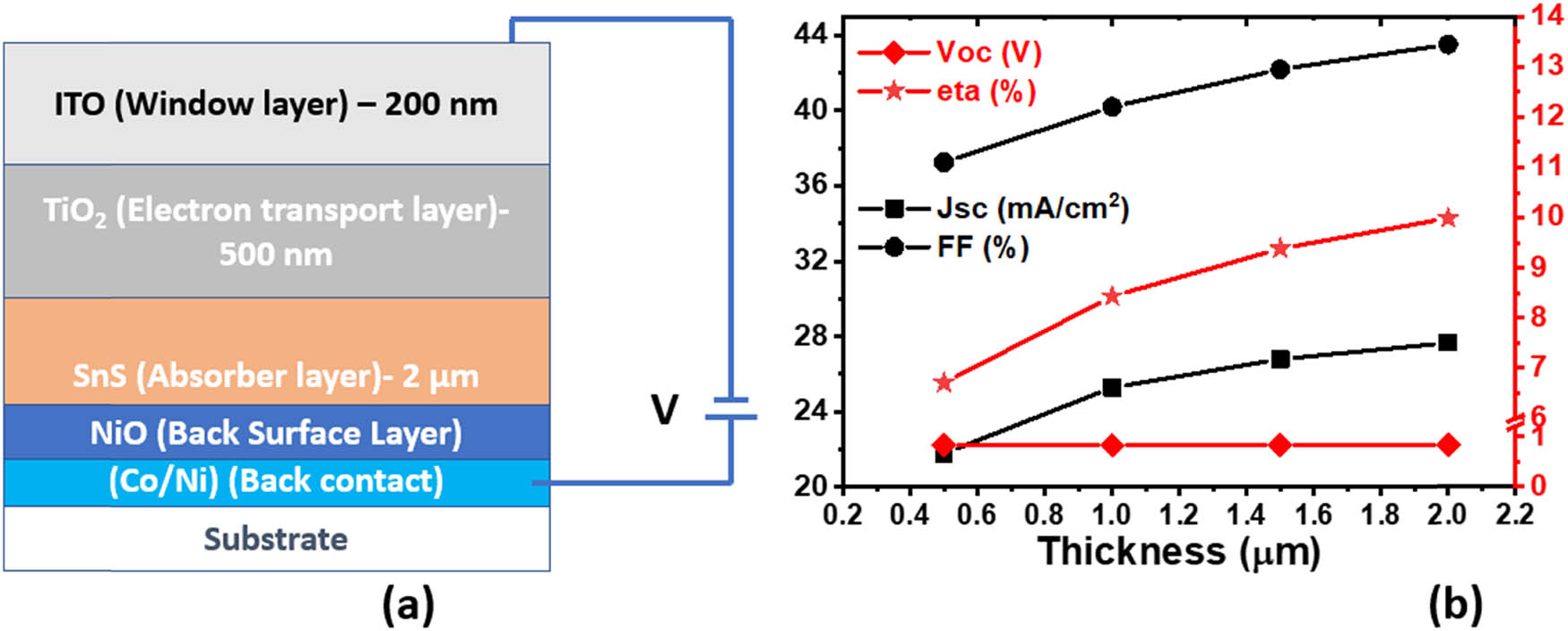
Figure 1
(a) Structural representation of a solar cell device based on SnS, TiO2, and ITO. (b) Adjustment of solar cell parameters (J SC, V OC, ɳ, and fill factor) with the thickness of SnS.
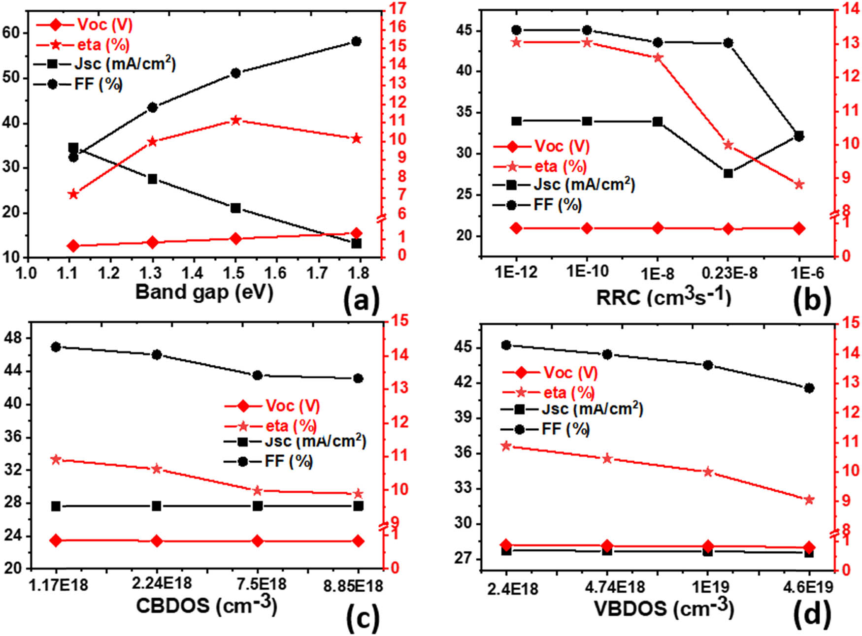
Figure 2
Variations in the parameters of a solar cell (J SC, V OC, ɳ, and fill factor) with (a) band gap, (b) radiative recombination coefficient, (c) CBDOS, and (d) VBDOS of SnS.
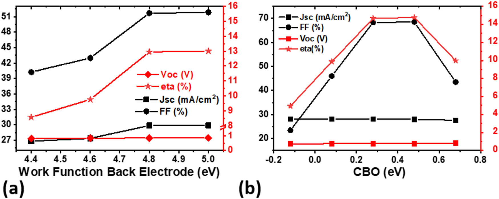
Figure 3
(a) Variations in parameters of solar cells with the work function of back contacts and (b) CBO.
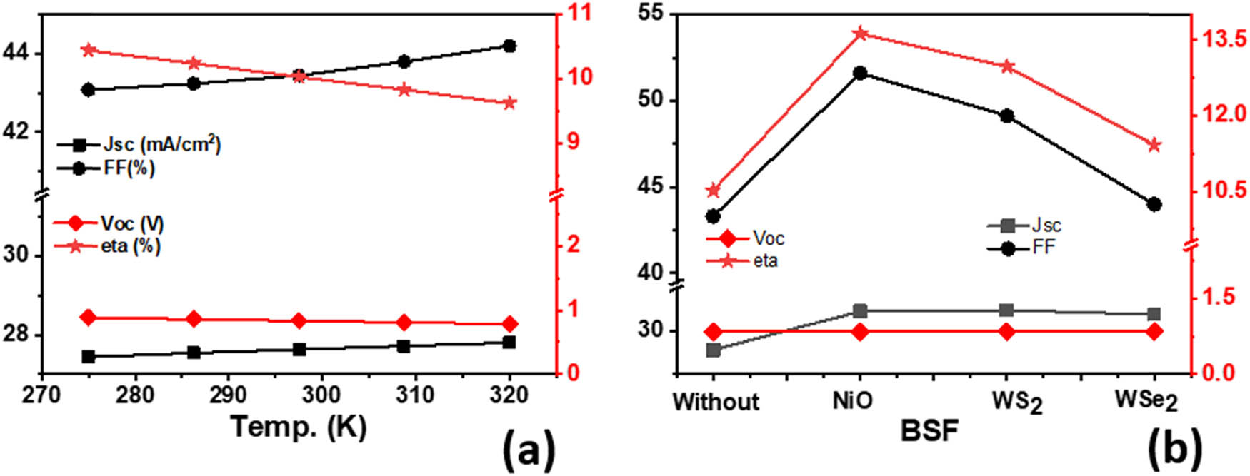
Figure 4
Variation in the cell parameters with (a) operating temperature and (b) without and with BSF layers.
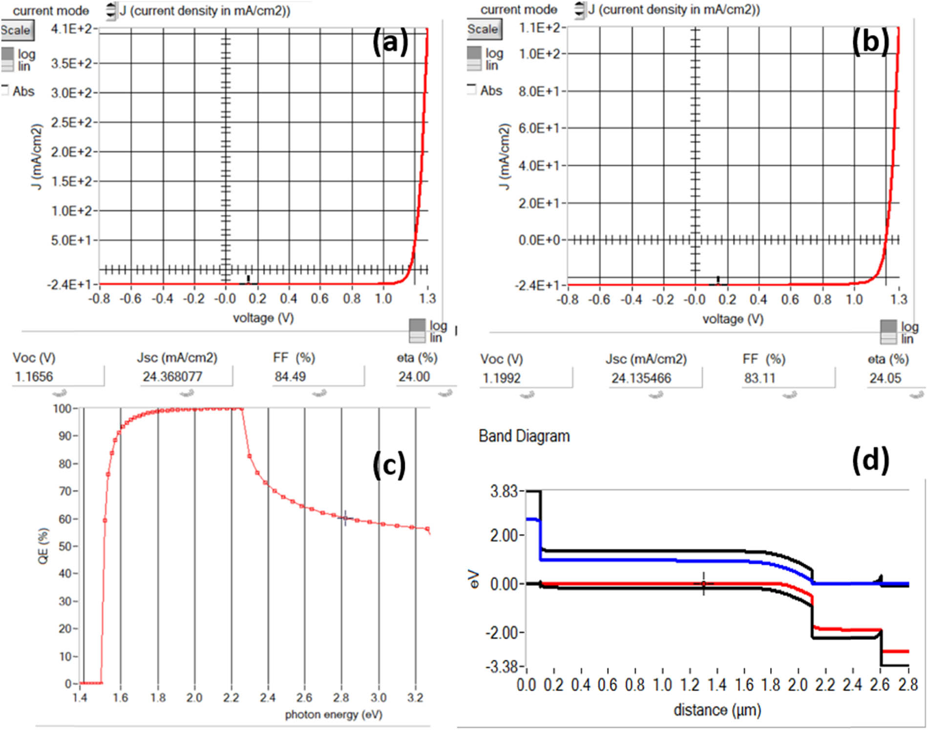
Figure 5
J–V curves of the output panel at operating temperatures of (a) 300 K and (b) 275 K, (c) quantum efficiency of the cell, and (d) energy band alignment for the cell.