
Aluminium metal matrix composites (AMMCs) are finding application in aerospace, automobile and civil industries. The machining capability for fabricating components in AMMCs is challenging due to their intricate metal structure, an example of which is the presence of reinforcement, that reduces the cutting efficiency of the tool. The wirecut electrical discharge machining (WEDM) is used in the manufacturing industries to fabricate intricate shapes and components in difficult-to-machine materials. WEDM is a well-known unconventional machining system for manufacturing complicated shapes in difficult-to-cut materials. WEDM is mainly used in the tool room for developing tool and dies. The advantages of WEDM are non-contact type, good geometrical accuracy and efficiency. In recent years, the emergence of new sustainable materials that can offer a good range of performance has upheld the research interest in the development and application of metal matrix composites (MMCs). An overview of the literature is presented in Table 1.
A brief overview of the literature
| S. No. | Process parameters considered | Work material investigated | Work description | Outcome of the investigation |
|---|---|---|---|---|
| 1 | Pulse on time, pulse off time, wire feed rate, current, voltage, thermal conductivity, co-efficient of thermal expansion, density and wire tension [1] | Al 2124 SiCp MMCs | In the WEDM of AlSiCp MMC, DA and ANN-based predicted models for surface roughness and MRR were developed. | With an increase in pulse duration and thermal conductivity, the rate of material removal and surface roughness both increase significantly. |
| 2 | Pulse on time, pulse off time and wire feed [2] | HEA-reinforced aluminium metal–metal composite | The best parameter combination for a better surface finish, a faster MRR and a smaller KW is found using the Taguchi method and an L18 OA. | The pulse ON time has a significant influence on surface roughness (76.70%), KW (41.96%) and MRR (35.37%), and increasing the pulse ON time enhances the response variables. |
| 3 | Pulse on time, pulse off time, wire feed, wire tension, current and voltage [3] | AA6061-TiB2 | Studied the effect of reinforcement and wire material on the surface roughness in MMCs. | The results of the experiments show that the percentage of particle reinforcement was the most important factor in surface quality (62.04%) and machinability (34.2%). The machinability and surface quality of the TiB2 (5 wt.%) reinforced composite are excellent. Zinc-coated brass wire outperforms plain brass wire. |
| 4 | Pulse on time, pulse off time, wire feed and wire tension [4] | SiCp/Al composite | Prepared casted, coated, annealed and plastic processed wire for WEDM of MMCs. | The use of zinc coating on the wire resulted in increased MRR by 16.67%, reduced surface roughness by 21.18% and reduced wire breakage by 16.67% under the same discharge parameters when compared to brass wire electrode. |
| 5 | Short pulse time, wire feed rate, pulse width, spark gap, servo control mean reference voltage and time between pulses [5] | Al/ZrO2 (p)-metal matrix composite | Surface veracity aspects such as surface defects and recast layer thickness are investigated. | The result finding shows lower value of pulse on/off time, and frequency of pulse plays an important role in surface veracity. |
| 6 | Gap voltage, wire feed, pulse on time and pulse off time [6] | Al-Si12/B4C/fly ash | In WEDM of Al-Si12/B4C/fly ash composites, the effects of control parameters on MRR and surface roughness were examined using the Taguchi and ANOVA methods. | MRR increases as the pulse on time and reinforcement increase. Optimal machining conditions resulted in a maximum MRR of 38.01 mm3/min and a minimum surface roughness of 3.24 m. |
| 7 | Voltage, peak current, wire tension and dielectric pressure [7] | AMMCs with 6% and 8% weight fraction of Al2O3 | AMMC with weight fraction of Al2O3 is machined through WEDM | Based on the TOPSIS approach, the optimal MR and Ra process parameters were ascertained as 1.5 mm/min and 3.648 m, respectively. According to ANOVA, the peak current has a significant influence on MR and Ra. |
| 8 | Pulse on time and pulse off time, gap voltage, peak current and wire feed [8] | Aluminium-based composite materials (AA 7075) with (Al2O3) particles | The effect of wirecut EDM process parameters on MRR and surface roughness of Ni-P-coated and un-coated alumina-reinforced composite materials was investigated. | By combining grey relation analysis with principal component analysis, an ideal set of process parameters was observed. |
| 9 | Pulse on time and pulse off time, gap voltage, reinforcement and wire feed [9] | LM5/ZrO2 AMMCs | By using the Taguchi technique, the study sought to determine the optimal wire-EDM machining parameters for achieving maximum MRR, minimum SR and minimum kerf width KW. | The main statistical factors influencing MRR are the gap voltage (29.92%) and pulse on time (64.84%). |
| 10 | Pulse on time and pulse off time, gap voltage, percentage of reinforcement and wire feed [10] | Aluminium (LM25) rein-forced with fly ash and boron carbide (B4C) hybrid composites | WEDM experiments were planned and carried out using the Taguchi methodology's L27 OA approach, and the corresponding MRR and surface roughness were measured. | The grasshopper optimisation algorithm performed better than the others in terms of maximising volume removal rate and minimising surface roughness values, according to the results. |
| 11 | Doping percentage, reinforcement percentage, pulse on time and pulse off time, and wire feed [11] | Magnesium MMC | Investigation in WEDM has been carried out to oversee the effect of process variables on the machining performance parameters such as MRR and Ra of magnesium composite. | The results of the experiment show that increasing the duration of pulse ON and wire feed rate in WEDM increases the MRR. Surface roughness increases noticeably as pulse ON increases. |
| 12 | Cutting speed, feed and depth of cut [12] | Aluminium (AA6061) and alumina powder sized <1 mm with 99.9% purity | The study investigated the effects of varying alumina amounts ranging from 1 wt.% to 5 wt.% added to recycled aluminium chip using hot press forging. Ultimate tensile strength and elongation to failure were the primary responses studied. | The addition of 2 wt.% alumina to the recycled aluminium alloy produced high-quality and consistent results. |
| 13 | Current, pulse on time, wire speed, voltage and pulse off time [13] | SiCp reinforced Al6061 composite | The effect of parameters such as current, pulse on time, wire speed, voltage and pulse off time on wire-EDM machining of 4–8 wt.% SiCp/Al6061 alloy was investigated. | MRR was significantly influenced by current, pulse on time, pulse off time, wire speed and voltage. The MRR increased as the current, pulse on time, wire speed and voltage increased, but it decreased as the pulse off time and wire speed exceeded 700 rpm. |
| 14 | Stirring temperature, stirring speed, stirring time, preheat temperature of reinforced particles, preheat temperature of permanent die and squeeze pressure [14] | AlSi7Mg + alumina; scrap aluminium alloy + alumina; AlSi7Mg + SAC; scrap aluminium alloy + SAC | In the present study, stir-squeeze casting was successfully used to create AMCs using a novel method. The viability of using SAC from oil refineries as reinforcement material and SAAWs as the matrix material was examined. | According to the micrograph analysis, the scrap aluminium alloy alumina composite had the most uniform distribution of reinforcements and the lowest porosity among the four composites. |
| 15 | Current, pulse on time, wire feed rate, pulse off time, ultimate tensile strength and micro hardness [15] | AZ61 magnesium alloy with boron carbide and silicon carbide as an reinforcement with varying percentage levels | The fabricated magnesium MMC is machined through WEDM for MRR and surface roughness. | The highest MRR of 0.212 mm3/s was obtained at pulse on time of 115 μs and pulse off time of 50 μs, and the minimum values of surface roughness were obtained as 1.003942 μm. |
| 16 | Alumina weight percentage, amplitude percentage and pulse time [16] | SAAWs | Using a L9 OA and the Taguchi method, an experimental study was carried out. Multi-objective optimisation based on ratio analysis technique was used for optimisation. | The findings showed that compared to other composites, SAAWs reinforced with 1 weight percent of nanosized alumina particles and 5.5 weight percent of micro sized alumina particles had lower porosity and metal loss (wear), higher hardness, tensile strength, and compressive strength. |
| 17 | Cutting speed, surface topography, surface roughness, recast layer formation, residual stresses and microstructural and metallurgical alterations [17] | Inconel 706 | To determine the feasibility of machining these components, research was carried out on Inconel 706 superalloy using the WEDM process. | Despite the fact that zinc-coated wire improves productivity, hard brass wire was noticed to be advantageous in terms of improved surface quality of machined parts. |
| 18 | Pulse off time, pulse on time, gap voltage and peak current [18] | [Difficult-to-cut materials] | The study concentrated on the impacts of various optimisation techniques, such as single and multi-objective techniques, on difficult-to-cut materials. | Reviewed the recent and early research articles on the WEDM process to cut hard conductive materials along with single response and multi response optimisation. |
| 19 | Pulse off time, pulse on time, gap voltage and peak current [19] | A286 superalloy | Optimised the WEDM performances by particle swarm optimisation. | The best MRR and surface roughness, respectively, were 19.90 mm2/min and 3.49 m. |
| 20 | Pulse off time, pulse on time, gap voltage and peak current [20] | Hard-to-cut materials | Six algorithms, namely MOALO, NSMFO, MODA, MOGWO, MOGOA and NSWOA, are used in the Pareto optimisation of a WEDM process. | The results reveal that MOGWO, MOGOA and MODA can identify the optimum solutions in 47%, 28% and 20% of the situations, respectively. |
AMMCs, aluminium metal matrix composites; ANN, artificial neural network; ANOVA, analysis of variance; DA, dimensional analysis; KW, kerf width; MMC, metal matrix composite; MOALO, multi-objective ant lion optimisation; MODA, multi-objective dragonfly algorithm; MOGOA, multi-objective grasshopper optimisation algorithm; MOGWO, multi-objective grey wolf optimiser; MRR, material removal rate; NSMFO, non-dominated sorting moth flame optimisation; NSWOA, non-dominated sorting whale optimisation algorithm; OA, orthogonal array; SAAWs, scrap aluminium alloy wheels; SAC, spent alumina catalyst
In this research, the machinability of scrap aluminium alloy-based composites is machined using WEDM, and this study paves way for reusability and sustainable product development. In general, the alloy wheel already consists of silicon and magnesium, and addition of Al2O3 greatly improves the mechanical properties of the material. AMMCs is finding applications in various industries such as aerospace, marine and automobile, primarily in the body structure. The machining of AMMCs becomes an essential area of research due to the above applications. In this research, the performance of zinc-coated wire on AMMC was analysed through experimental performance by varying one parameter at a time and characterisation using scanning electron microscopy (SEM) and energy-dispersive x-ray spectrometry (EDS). Moreover, the L18 orthogonal array (OA) experimental design is considered to find the optimal combination of factors using the CRiteria Importance Through Intercriteria Correlation (CRITIC) and simple additive weighting (SAW) methods, and the significant factor affecting the WEDM process is ascertained using the ANOVA method.
Electronic Computer Numerical Control (CNC) WEDM is used for making slots on the fabricated MMCs. A zinc-coated brass wire electrode of Φ 0.25 mm is used for the cutting. The zinc coating improves the flushability and instant cooling ability of the wire [15]. The workpiece is formed from the scrap aluminium alloy wheels (SAAWs) of vehicles as a matrix and 5% alumina as reinforcement.
The AMMCs are fabricated through stir-squeeze casting technique. The SAAWs of necessary size are melted in an electric furnace on a graphite crucible and heated to a temperature of 900°C. To enhance the wettability among the matrix and the reinforcements, magnesium of 1wt.% is added to the melt. A two-blade stirrer is used for 5 min to mix the molten metal to ensure uniform mixing of reinforcement in the Al matrix. The molten mixture is poured into a permanent mould of dimensions 50 mm × 50 mm × 250 mm and cooled and solidified at room temperature. The workpiece consists of recycled aluminium alloy reinforced with silicon and magnesium, and the chemical composition of the workpiece is confirmed using energy-dispersive X-ray spectroscopy (EDS) analysis, as shown in Figure 1 and in Table 2. Deionised water is used as the dielectric medium. The material is removed by a sequence of discrete discharges between the wire electrode and the workpiece in the presence of dielectric fluid, which creates a path for each discharge as the fluid becomes ionised in the gap. The area where discharge takes place is heated to a tremendously high temperature, so that the surface is melted and removed [16,17,18]. The removed particles are flushed away by the flowing dielectric fluids.
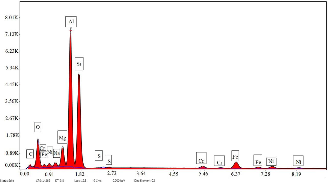
EDX analysis of AMMC. AMMC, aluminium metal matrix composite; EDX, energy-dispersive X-ray
Chemical compositions of composite materials
| Element | Weight percentage | Atomic percentage | Error percentage |
|---|---|---|---|
| C K | 4.49 | 9.08 | 21.36 |
| O K | 16.53 | 25.11 | 9.43 |
| Na K | 1.86 | 1.96 | 11.36 |
| Mg K | 5.01 | 5.01 | 6.53 |
| Al K | 31.72 | 28.58 | 4.71 |
| Si K | 29.47 | 25.5 | 6.15 |
| S K | 0.07 | 0.05 | 29.63 |
| Cr K | 1.44 | 0.67 | 12.35 |
| Fe K | 6.53 | 2.84 | 5.11 |
| Ni K | 2.9 | 1.2 | 10.1 |
The experimental variables, namely voltage (Vs), wire feed rate (Fw), current (Ip), pulse on time (ONT) and pulse off time (OFFT), were selected for the purpose of machining. Machining time is recorded for each experimental combination, and time duration for breakage of wire is noted. The input variables and levels are provided in Table 3. Each control variable is analysed at five levels to determine the wire breakage for the WEDM process. Table 4 presents the scheme of the conducted experiment and first incidence of wire breakage in seconds, corresponding to the fabrication of a slot of the size 5 mm × 10 mm. Figure 2 shows the overview of workplan and methodology.
Control variables and their levels
| Control variables | Symbols | Units | Level 1 | Level 2 | Level 3 | Level 4 | Level 5 |
|---|---|---|---|---|---|---|---|
| Voltage | V | V | 30 | 40 | 50 | 60 | 70 |
| Wire feed rate | Fw | mm/min | 3 | 4 | 5 | 6 | 7 |
| Current | Ip | A | 10 | 15 | 20 | 25 | 30 |
| Pulse on time | ONT | μs | 100 | 105 | 110 | 115 | 120 |
| Pulse off time | OFFT | μs | 50 | 55 | 60 | 65 | 70 |
Performance measure of wire breakage
| Ex. No. | V | Fw | IP | ONT | OFFT | First incidence of wire breakage in seconds |
|---|---|---|---|---|---|---|
| 1 | 30 | 7 | 30 | 120 | 70 | 304 |
| 2 | 40 | 7 | 30 | 120 | 70 | 60 |
| 3 | 50 | 7 | 30 | 120 | 70 | 32 |
| 4 | 60 | 7 | 30 | 120 | 70 | 27 |
| 5 | 70 | 7 | 30 | 120 | 70 | 22 |
| 6 | 70 | 3 | 30 | 120 | 70 | - |
| 7 | 70 | 4 | 30 | 120 | 70 | 28 |
| 8 | 70 | 5 | 30 | 120 | 70 | 21 |
| 9 | 70 | 6 | 30 | 120 | 70 | 19 |
| 10 | 70 | 7 | 30 | 120 | 70 | 15 |
| 11 | 70 | 7 | 10 | 120 | 70 | 727 |
| 12 | 70 | 7 | 15 | 120 | 70 | 32 |
| 13 | 70 | 7 | 20 | 120 | 70 | 26 |
| 14 | 70 | 7 | 25 | 120 | 70 | 23 |
| 15 | 70 | 7 | 30 | 120 | 70 | 21 |
| 16 | 70 | 7 | 30 | 100 | 70 | 1114 |
| 17 | 70 | 7 | 30 | 105 | 70 | 847 |
| 18 | 70 | 7 | 30 | 110 | 70 | 30 |
| 19 | 70 | 7 | 30 | 115 | 70 | 25 |
| 20 | 70 | 7 | 30 | 120 | 70 | 19 |
| 21 | 70 | 7 | 30 | 120 | 50 | 120 |
| 22 | 70 | 7 | 30 | 120 | 55 | 90 |
| 23 | 70 | 7 | 30 | 120 | 60 | 8 |
| 24 | 70 | 7 | 30 | 120 | 65 | 7 |
| 25 | 70 | 7 | 30 | 120 | 70 | 6 |
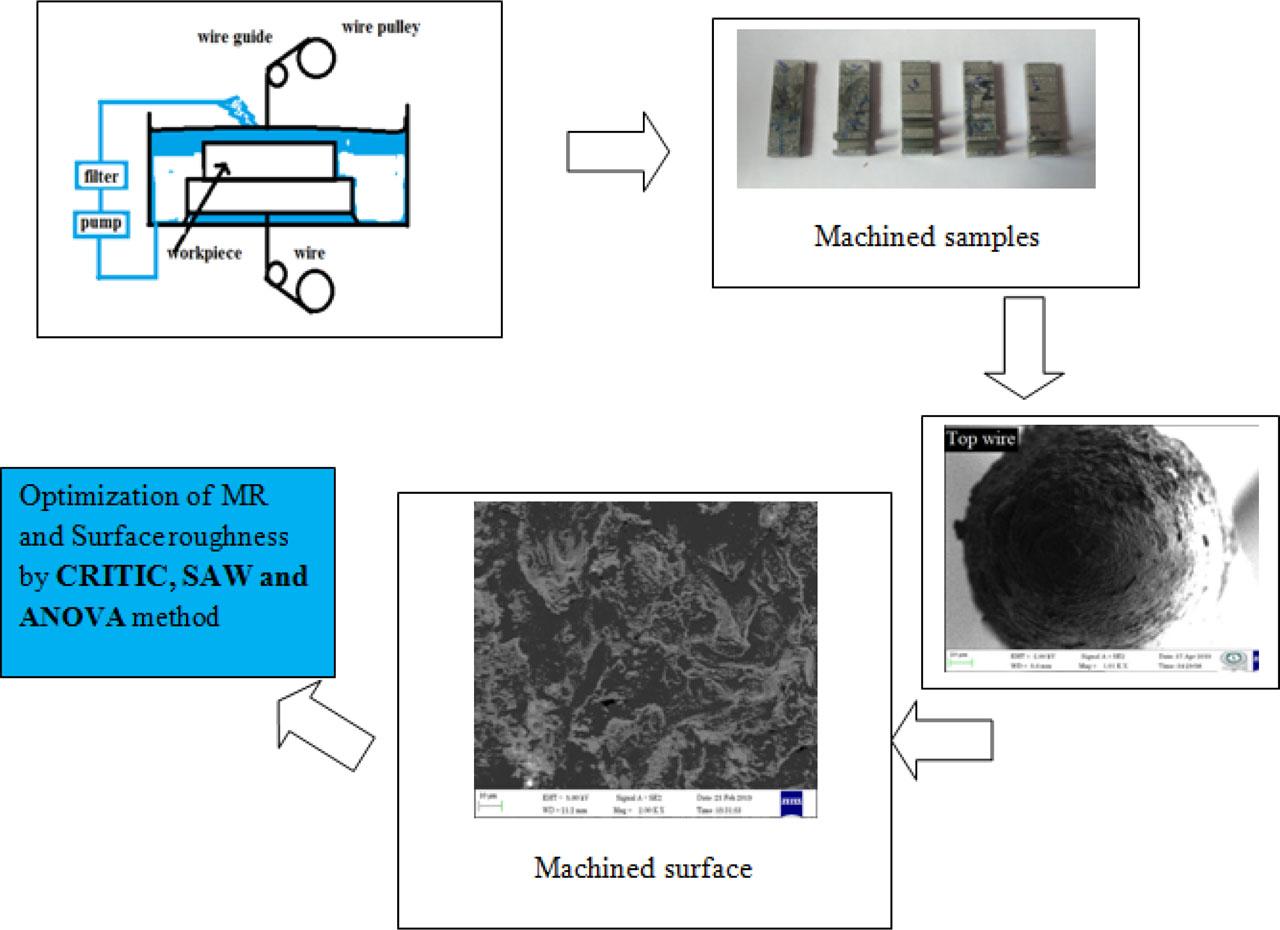
Overview of the experimental work and methodology. ANOVA, analysis of variance; CRITIC, CRiteria Importance Through Intercriteria Correlation; MR, machining rate; SAW, simple additive weighting
Table 5 presents the levels and parameters used for the performance optimisation of WEDM process. Machining rate (MR) and surface roughness (Ra) are considered as performance measures. Five parameters at the third level are considered for this experiment, and accordingly 10 applicable degrees of freedom are used; resultantly, L18 OA is considered for executing the experiments, as indicated in Table 6.
Parameters and their levels chosen for optimisation
| Control variables | Symbols | Units | Level 1 | Level 2 | Level 3 |
|---|---|---|---|---|---|
| Voltage | V | V | 30 | 50 | 70 |
| Wire feed rate | Fw | mm/min | 3 | 5 | 7 |
| Current | Ip | A | 10 | 20 | 30 |
| Pulse on time | ONT | μs | 100 | 110 | 120 |
| Pulse off time | OFFT | μs | 50 | 60 | 70 |
L18 OA
| Exp. No. | V | Fw | Ip | ONT | OFFT | MR mm/min | Surface roughness (Ra) μm |
|---|---|---|---|---|---|---|---|
| 1 | 30 | 3 | 10 | 100 | 50 | 1.02 | 3.600 |
| 2 | 30 | 5 | 20 | 110 | 60 | 1.02 | 3.795 |
| 3 | 30 | 7 | 30 | 120 | 70 | 1.52 | 3.748 |
| 4 | 50 | 3 | 10 | 110 | 60 | 0.9 | 3.218 |
| 5 | 50 | 5 | 20 | 120 | 70 | 1.25 | 3.789 |
| 6 | 50 | 7 | 30 | 100 | 50 | 1.24 | 3.780 |
| 7 | 70 | 3 | 20 | 100 | 70 | 1.04 | 3.392 |
| 8 | 70 | 5 | 30 | 110 | 50 | 0.85 | 3.392 |
| 9 | 70 | 7 | 10 | 120 | 60 | 1.06 | 3.722 |
| 10 | 30 | 3 | 30 | 120 | 60 | 0.85 | 3.570 |
| 11 | 30 | 5 | 10 | 100 | 70 | 1.28 | 3.575 |
| 12 | 30 | 7 | 20 | 110 | 50 | 1.35 | 3.405 |
| 13 | 50 | 3 | 20 | 120 | 50 | 0.82 | 3.532 |
| 14 | 50 | 5 | 30 | 100 | 60 | 0.92 | 3.420 |
| 15 | 50 | 7 | 10 | 110 | 70 | 1.23 | 3.228 |
| 16 | 70 | 3 | 30 | 110 | 70 | 0.76 | 3.729 |
| 17 | 70 | 5 | 10 | 120 | 50 | 0.88 | 3.686 |
| 18 | 70 | 7 | 20 | 100 | 60 | 1.06 | 3.370 |
OA, orthogonal array
The CRITIC weighting method deals with the interdependence between the criteria. The CRITIC method is more appropriate for weighing up the weights of both conventional and modern performance measures, and it comprises all the information in the assessment criteria. Moreover, the SAW method is used to compute the index score.
The weights of the criteria play an essential role in deciding the actual degree of a criterion's control. In describing the output performance of WEDM, the indicator with the maximum weight is considered as the most significant indicator, and against this conceptual background, this research used the CRITIC weighting method to establish the weights of the MR and surface roughness by using the following steps:
Step 1: The normalisation of the decision matrix is represented in Eq. (1), where Zpq stands for the observation of MR and surface roughness:
Step 2: Find the standard deviation σq for indicator q.
Step 3: Find the symmetrical matrix k × k with the element sqr, which represents the linear correlation coefficient between the vectors zq and zr, respectively.
Step 4: Next, evaluate the contradiction that criterion q creates within the context of the decision scenario described by the remaining criterion, which is evaluated by the formula represented below in Eq. (5).
Finally, the following expression in Eq. (7) below represents the objective weight for indicator q:
To optimise the MR and surface roughness, this paper proposes to use the SAW method, as given in Eq. (8):
The greatest value Bp denotes the highest ranking for MR and surface roughness.
Figure 3 shows the effect of voltage on time for the first incidence of wire breakage while machining the slot in MMC. It is evident from the graph that at the parameter level of 30 V, 7 mm/min, 30 A, 120 μs (ONT) and 70 μs, the first incidence of wire breakage has occurred at 304 s, before the completion of the slot. At this instance, the slot dimension for the height is measured using a Vernier height gauge and marked height of 9.4 mm. It is clear that there is a shortage in the height by - 0.6 mm, thereby not allowing the completion of the slot. At a lower voltage level, there is a greater availability in the pulse on-current for machining, and accordingly the rapid movement of material is introduced in order to ensure slot completion. Increasing the voltage from 40 V to 70 V increases the production of gas bubbles, together with the bowing effect of the wire triggering the breaking of the wire. Moreover, in the WEDM process, the wire gap condition is also an important factor that decides the efficiency of machining. During the WEDM process, the presence of reinforcement varies the gap based on the agglomeration of reinforcement. During the higher voltage levels, the presence of clusters of reinforcements can be attributed to bulk removal material and sharp reinforcement existing in the delaminated areas, and, consequent to exposure to wire, these are the areas that are the first to initiate the damage; and as a result of this effect, the wire electrode experiences breakage for the higher voltage levels. The graph trend of Figure 3 shows that at 30 V, it took a long time for the breakage of wire to occur, and with an increase in the voltage level, a frequent failure in wire was noticed. Figures 4A and 4B show the SEM images of the machined surface of the completed slot. The complete machined surface shows a few occurrences of the Al2O3 and re-solidified areas. The sparse presence of Al2O3 prevents any encounter between the material used as reinforcement and the wire, thereby facilitating the completion of the slot.
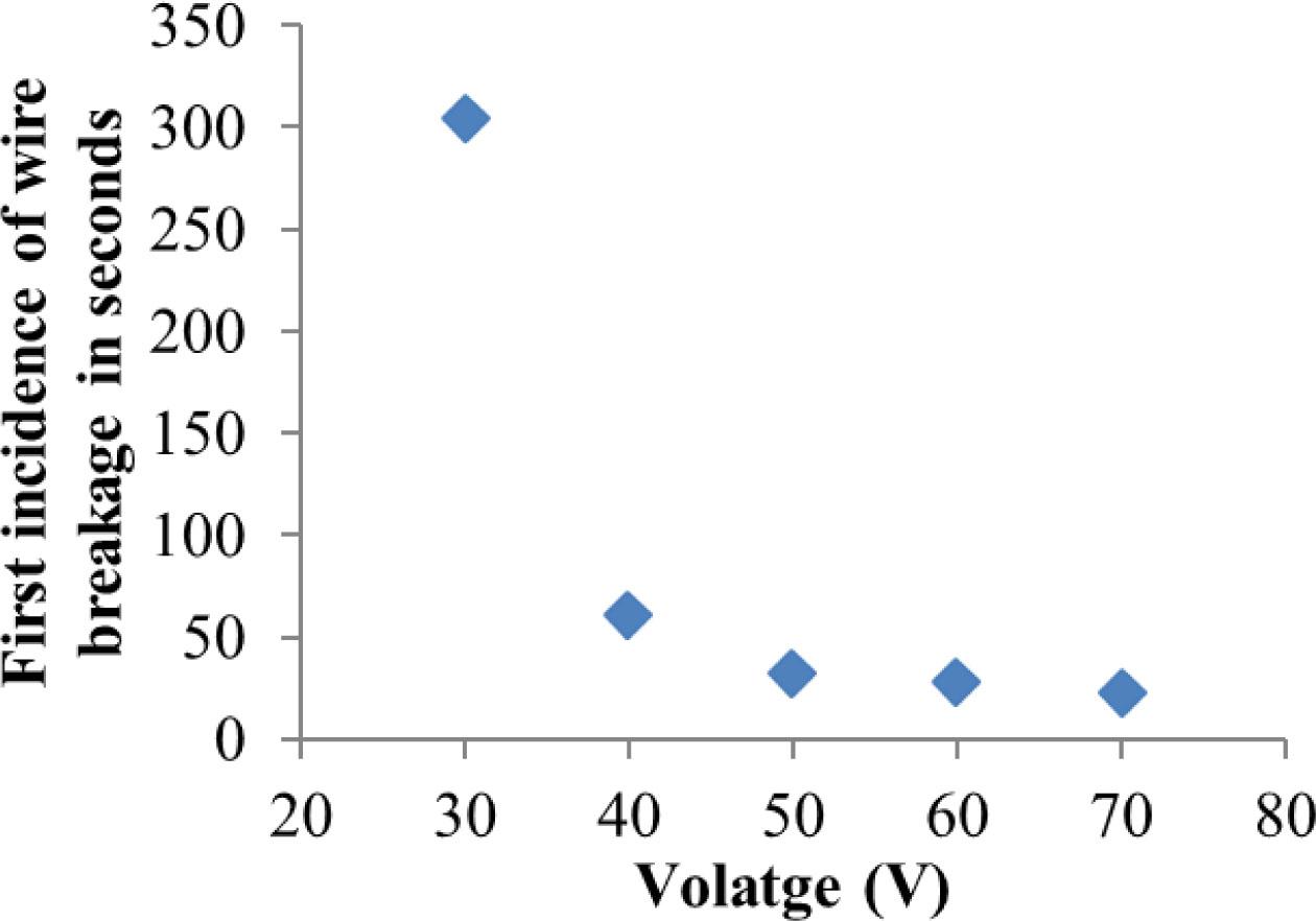
Effect of voltage on the first incidence of wire breakage at 7 mm/min, 30 A, 120 μs (ONT) and 70 μs
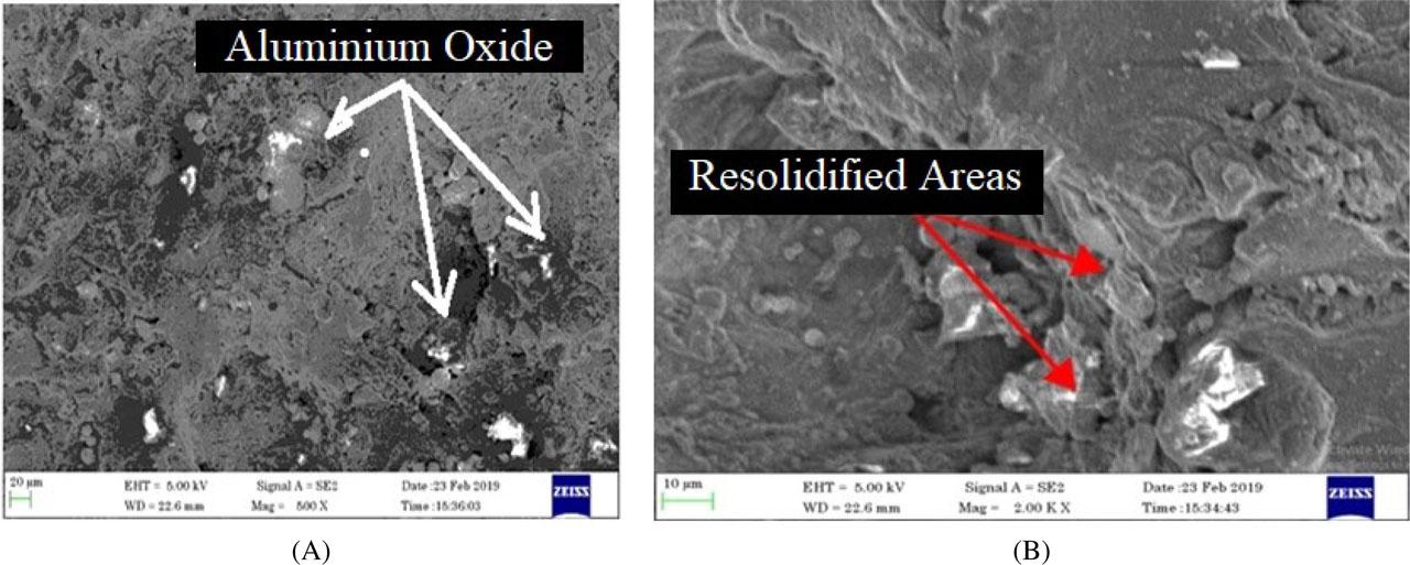
(A, B) SEM image of machined surface at 30 V, 7 mm/min, 30 A, 120 μs and 70 μs. SEM, scanning electron microscopy
Figures 5A and 5B show the SEM picture of wire before and after machining, and it is evident that no significant changes are observable, except for a small quantity of erosion and re-solidified surfaces. The condition of the wire confirms efficient machining for the parametric combination of 30 V, 7 mm/min, 30 A, 120 μs (ONT) and 70 μs.
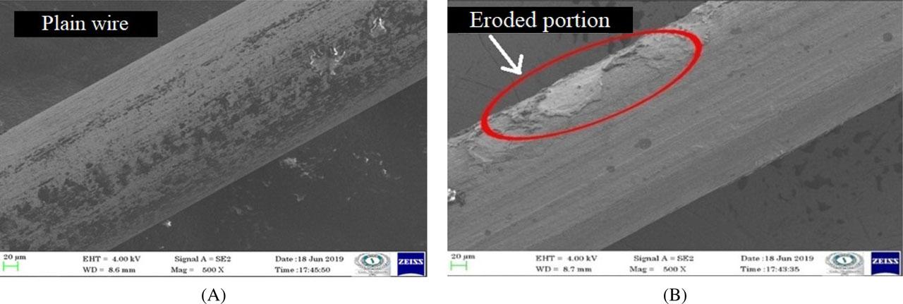
(A, B) SEM images of wire electrode surface after completing machining of the slot at conditions of 70 V, 3 mm/min, 30 A, 120 μs (ONT) and 70 μs. SEM, scanning electron microscopy
The primary parameter that significantly influences the WEDM process is the wire feed rate. The effect of wire feed rate on the machinability of a slot in AMMC is shown in Figure 6. As can be clearly observed from the graph, we have confirmation that usage of the discussed experimental combination of input parameters—i.e., 30 V, 3 mm/min, 30 A, 120 μs (ONT) and 70 μs—facilitates the completion of the slot without breakage of the wire, and the time taken to machine the slot is found to be 435 s. It is evident from the graph that the lower wire feed rate ensures the completion of machining of the slot without wire breakage. During the lower wire feed rate, high current passes through the wire, which allows the creation of sparks when it gets close to the conductive workpiece. Each spark is prolonged for few seconds, resulting in excess temperature, which is high enough to melt and evaporate the workpiece material. The higher electrical parameters and lower wire feed rate contributed to non-breakage of the wire. From this graph, it is evident that the wire breakage frequency increases with an increase in wire feed (Fw). The increase in wire feed rate from 3 mm/min to 4 mm/min shows a notable change in the wire breakage, and a further increase from 4 mm/min to 7 mm/min increases the frequency of the wire breakage. Figures 7A and 7B show the SEM image of the eroded and broken wire of the top and bottom portions, at the experimental condition of 70 V, 7 mm/min, 30 A, 120 μs and 70 μs. It is clear from the figure that the erosion and breakage of the wire is not instantaneous, and that a cone shape is formed on either portion of the wire. It is noted that the centre portion of the wire shows no evidence of a melted zone and occurrence of breakage is envisaged due to weakening of mechanical properties. The presence of protruding sharp-edged Al2O3 on the workpiece surface after melting of matrix material creates the shearing effect on the wire.
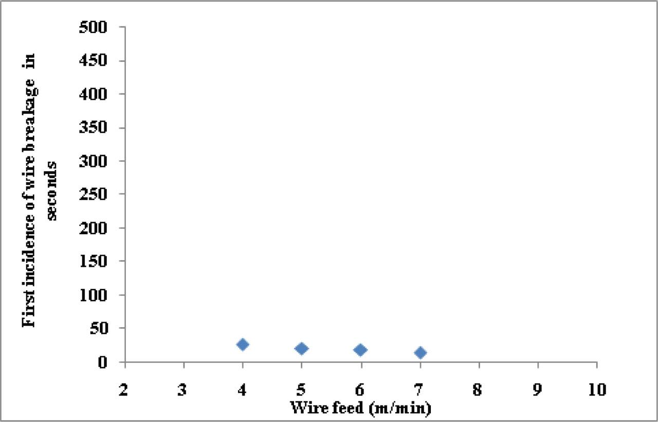
Wire behaviour effect between wire feed and first incidence of wire breakage
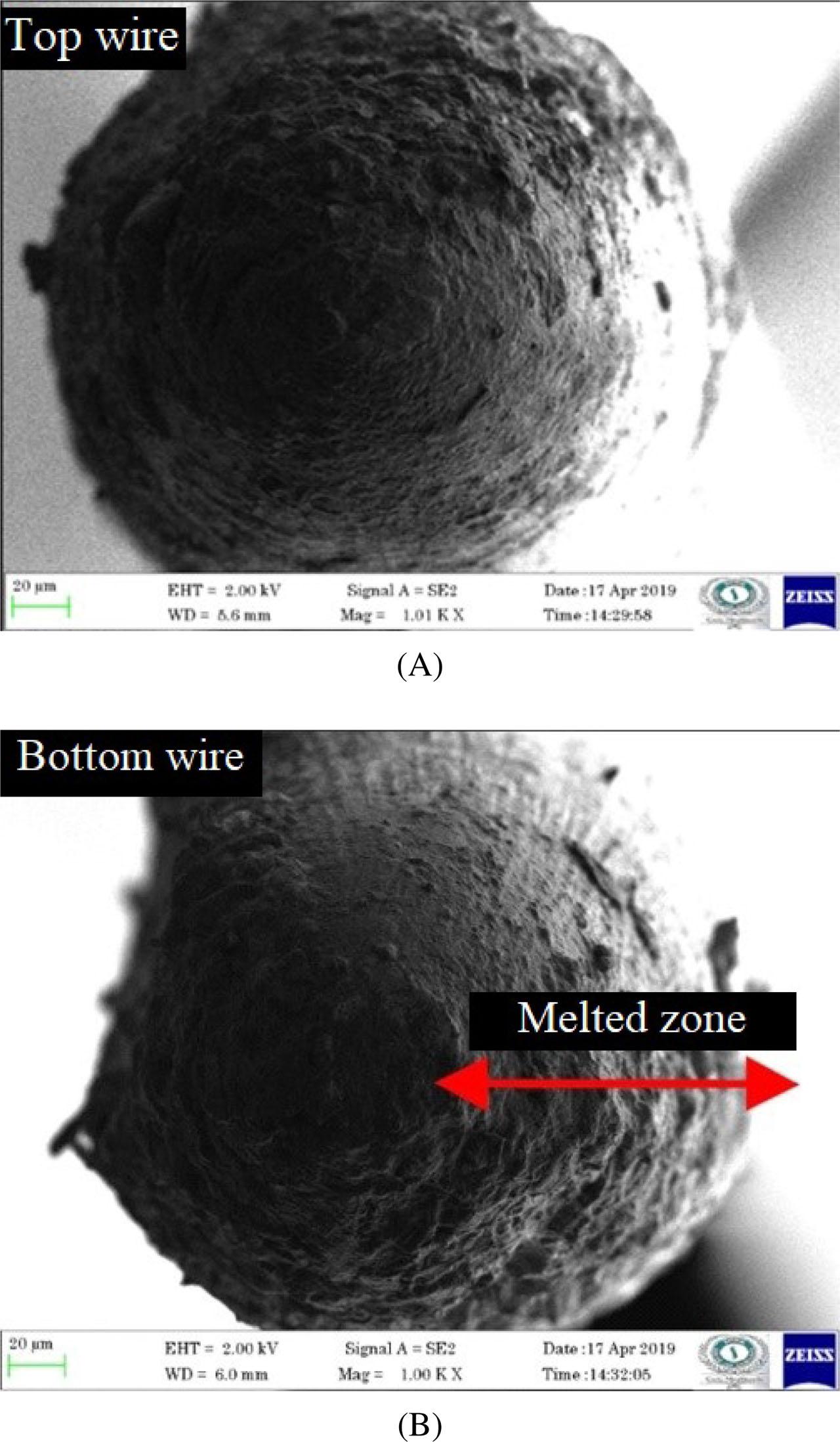
Cross-sectional view of the eroded and broken wire: (A) top portion and (B) bottom portion at 70 V, 7 mm/min, 30 A, 120 μs (ONT) and 70 μs
In WEDM, zinc-coated wire electrode occupies a considerable percentage of the machining cost. Therefore, to attain stable machining without wire breakage, it is required to set a low wire feed rate and a higher level of electrical parameters.
Figure 8A shows the SEM picture of the machined surface at the parametric combination of 70 V, 3 mm/min, 30 A, 120 μs (ONT) and 70 μs. The higher-level values of voltage, current and pulse on/off time create the high-density sparks that in turn create craters and pits. Figure 8B shows the rapidly melted and solidified regions on the surface of the slot. Hence, the low feed rate ensures stable machining.
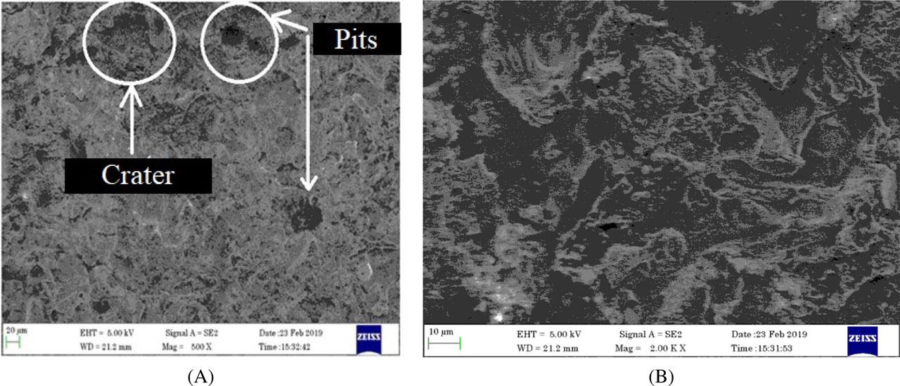
(A,B) SEM image of machined surface at the parametric combination of 70 V, 3 mm/min, 30 A, 120 μs (ONT) and 70 μs. SEM, scanning electron microscopy
Figure 9 demonstrates that if we consider the applicable wire breakage as the one corresponding to the lowest value of peak current (30 A), 727 s is obtained as the time taken to machine the slot up to a depth of 9.8 mm. Increase in peak current increases the rate of heat energy. Melting and vaporisation of the wire occur at a rapid rate during the continuous increment of peak current, thereby leading to wire breakage during machining. The peak current governs the maximum amount of amperage for machining the workpiece. Roughing operations are possible with the flow of high current, but they may lead to the creation of cavities. Continuous increment of peak current improves MR but reduces the surface roughness. In AMMC, the continuous increment of peak current leads to increasing frequency of wire breakage.
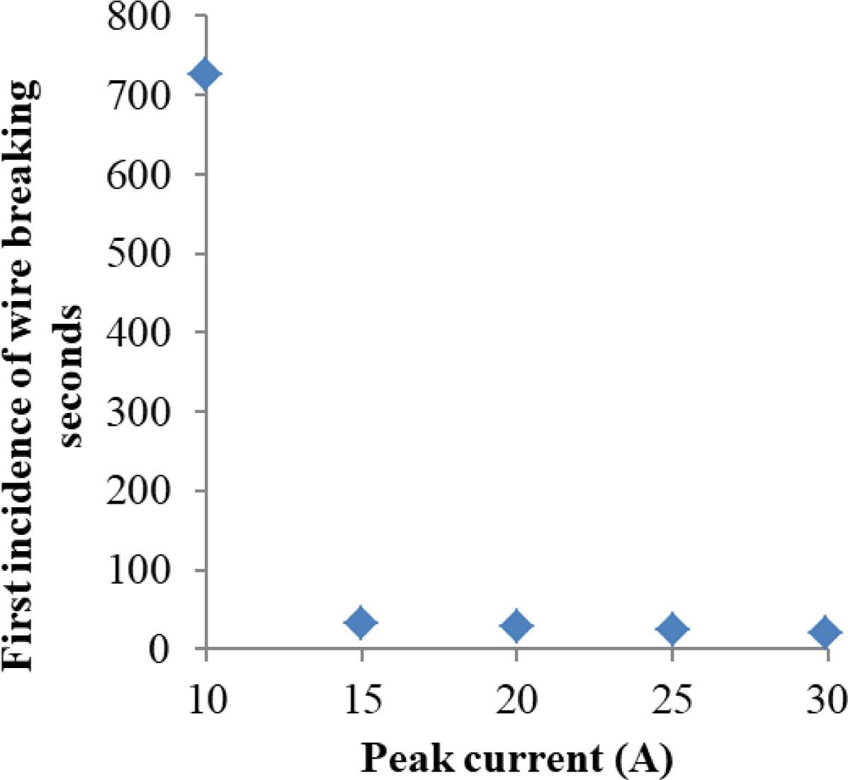
Effect of peak current on the first occurrence of wire breakage
Figure 10 indicates the effect of pulse on time on the wire breakage during the machining of MMCs. The two slots were successfully completed without wire breakage at 1,115 s and 847 s. Further increase in the pulse on time results in wire breakage. It is evident from the graph that no wire breakage has occurred at lower pulse on time; and with increase in the pulse on time, the frequency of breakage increases. It is due to the fact that increase in pulse on time increases the discharge rate. The high frequency discharge increases the erosion and breaking of the wire. Another important factor for the cause of wire breakage is short circuit. Short circuits take place due to longer pulse on time, and the material removed from the work-piece creates the conductive bridge, resulting in unwanted sparking. Hence, an increased frequency of sparking contributes towards frequent breaking of wires.
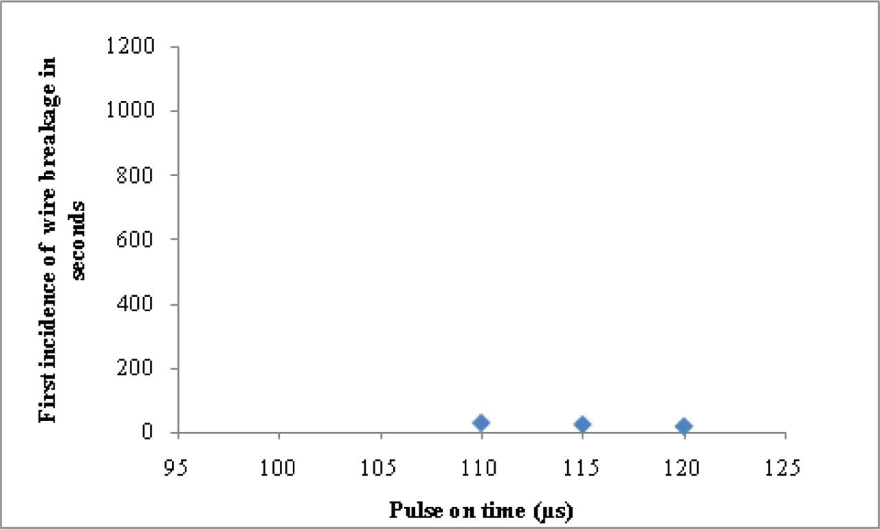
Wire behaviour effect for various pulse on time
On comparing the other parameter, the pulse off time (OFFT) has not attained complete machining, as shown in Figure 11. In AMMCs workpiece, reinforcements are used to increase the strength of the material, and this amalgamation of particles causes clustering of particles and weak matrix-reinforcement bonding. Therefore, when a proper gap is not maintained during wire travel, this results in frequent wire breakages owing to the protrusion of reinforcement particles and the resultant sharp corners. SEM image of the incomplete slot machined at the parameter combination of 70 V, 7 mm/min, 310 A, 120 μs (ONT) and 50 μs is shown in Figure 12, and the time for the first wire breakage is found to be 120 μs (ONT). The presence of protruded Al2O3 is noticed on the wire travel zone.
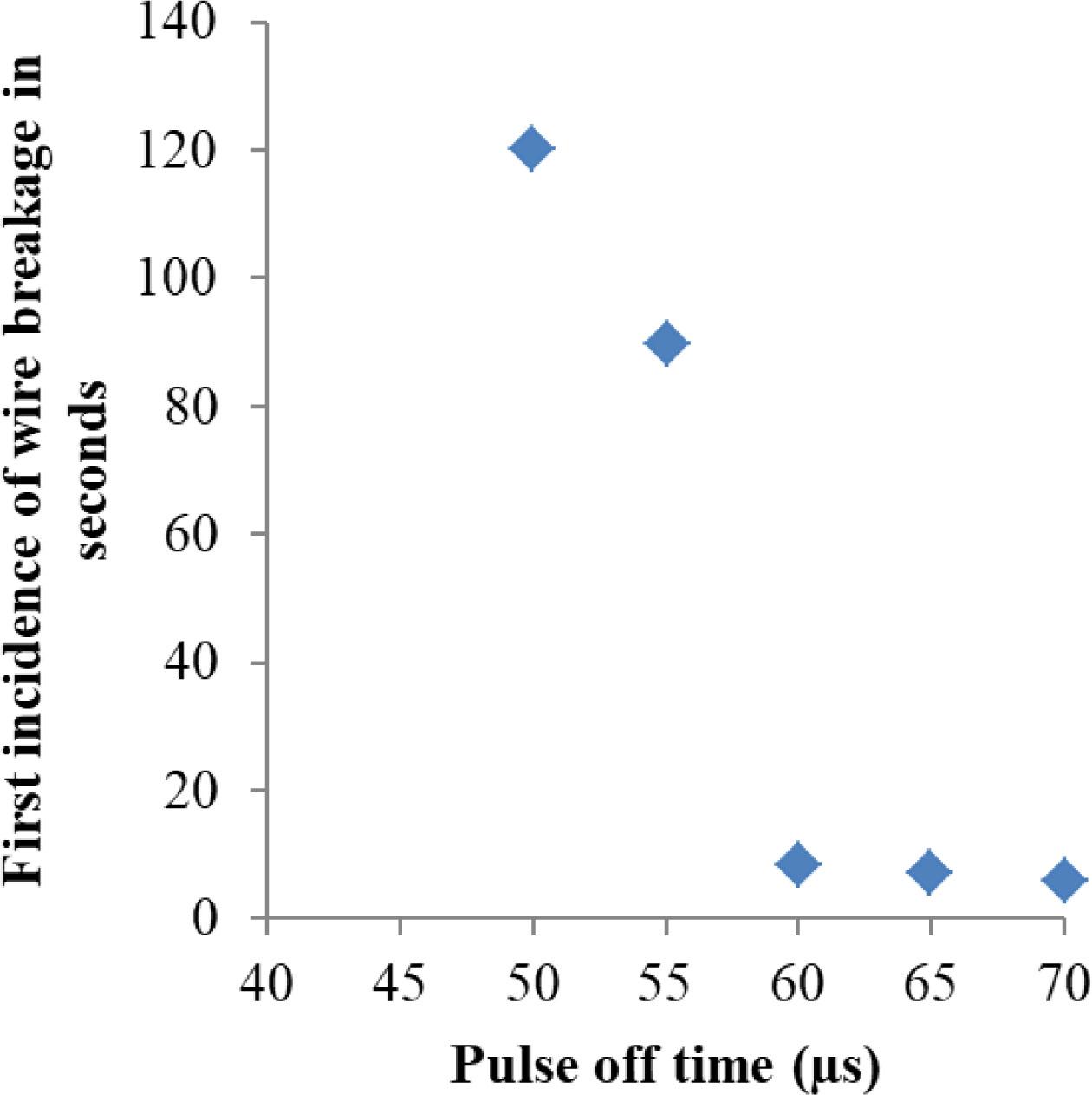
Effect of pulse off time on the wire behaviour (70 V, 7 mm/min, 310 A and 120 μs [ONT ])
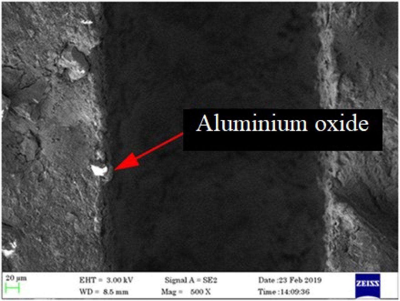
SEM graph of the machined slot at an experimental condition of 70 V, 7 mm/min, 310 A, 120 μs (ONT) and 50 μs. SEM, scanning electron microscopy
As per Eqs (1)–(8), the weights for the criteria (MR and Ra) were calculated as 0.4549 and 0.5450, respectively, and are presented in Table 7. Table 8 shows the normalised values of MR and Ra determined based on Eqs (1)–(8). Based on the CRITIC and SAW methods, the parameter combination of 30 V, 7 mm/min, 30 A, 120 μs (ONT) and 70 μs (OFFT) is the first ranked for higher MR and lower Ra. Additionally, 30 V, 7 mm/min, 20 A, 110 μs (ONT) and 50 μs (OFFT) is the second ranked combination. The results of the ANOVA are represented in Table 9. The ANOVA for MR and Ra shows that wire feed rate and voltage contribute 47.82% and 21.23%, respectively, for MR; and pulse on time shows 23.06% for surface roughness.
Standard deviation, criterion value and weighted value
| Criteria | Standard deviation, σ | Quantity of information, dq | Weight value, Wq |
|---|---|---|---|
| MR | 0.2779 | 0.3200 | 0.4549 |
| Surface roughness, Ra | 0.3329 | 0.3833 | 0.5450 |
MR, machining rate
Normalised decision matrix for the CRITIC and SAW methods
| Normalised values by the CRITIC method | Normalised values by the SAW method | Bp | Ranking | ||
|---|---|---|---|---|---|
| 0.3421 | 0.3379 | 0.2230 | 0.2385 | 0.7925 | 10 |
| 0.3421 | 0 | 0.2230 | 0.2514 | 0.7675 | 14 |
| 1 | 0.0814 | 0.3323 | 0.2483 | 0.9229 | 1 |
| 0.1842 | 1 | 0.1967 | 0.2131 | 0.8144 | 9 |
| 0.6447 | 0.0104 | 0.2733 | 0.2510 | 0.8370 | 6 |
| 0.6315 | 0.026 | 0.2711 | 0.2504 | 0.8351 | 7 |
| 0.3684 | 0.6984 | 0.2273 | 0.2247 | 0.8284 | 8 |
| 0.1184 | 0.6984 | 0.1858 | 0.2247 | 0.7715 | 13 |
| 0.3947 | 0.1265 | 0.2317 | 0.2465 | 0.7885 | 11 |
| 0.1184 | 0.3899 | 0.1858 | 0.2365 | 0.7457 | 15 |
| 0.6842 | 0.3812 | 0.2798 | 0.2368 | 0.8737 | 4 |
| 0.7763 | 0.6759 | 0.2951 | 0.2255 | 0.9192 | 2 |
| 0.0789 | 0.4558 | 0.1792 | 0.234 | 0.7420 | 16 |
| 0.2105 | 0.6499 | 0.2011 | 0.2265 | 0.7882 | 12 |
| 0.6184 | 0.9826 | 0.2689 | 0.2138 | 0.9115 | 3 |
| 0 | 0.1143 | 0.1661 | 0.2470 | 0.6978 | 18 |
| 0.1578 | 0.1889 | 0.1924 | 0.2442 | 0.7392 | 17 |
| 0.3947 | 0.7365 | 0.2317 | 0.2232 | 0.8377 | 5 |
CRITIC, CRiteria Importance Through Intercriteria Correlation; SAW, simple additive weighting
ANOVA results for MR and Ra
| Source of variation | Degree of freedom | Sum of squares | Mean sum of squares | F value | p value | % of Contribution |
|---|---|---|---|---|---|---|
| Surface roughness | ||||||
| Voltage (V) | 2 | 0.04409 | 0.022046 | 0.43 | 0.669 | 7.03 |
| Wire feed rate | 2 | 0.03265 | 0.016323 | 0.32 | 0.739 | 5.21 |
| Current | 2 | 0.03130 | 0.015649 | 0.30 | 0.748 | 4.99 |
| Pulse on time | 2 | 0.14463 | 0.072317 | 1.40 | 0.308 | 23.06 |
| Pulse off time | 2 | 0.01268 | 0.006342 | 0.12 | 0.886 | 2.02 |
| Error | 7 | 0.36188 | 0.051698 | 57.69 | ||
| Total | 17 | 0.62724 | 100 | |||
| MR | ||||||
| Voltage (V) | 2 | 0.16103 | 0.080517 | 9.28 | 0.011 | 21.23 |
| Wire feed rate | 2 | 0.36270 | 0.181350 | 20.90 | 0.001 | 47.82 |
| Current | 2 | 0.01343 | 0.006717 | 0.77 | 0.497 | 1.77 |
| Pulse on time | 2 | 0.01710 | 0.008550 | 0.99 | 0.420 | 2.25 |
| Pulse off time | 2 | 0.14343 | 0.071717 | 8.26 | 0.014 | 18.91 |
| Error | 10 | 0.06075 | 0.008679 | 8.01 | ||
| Total | 17 | 0.75845 | 100.00 | |||
ANOVA, analysis of variance; MR, machining rate
For the first time, the WEDM of a new kind of AMMC produced using scrap aluminium alloy wheels reinforced with 5% alumina in a stir-squeeze casting setup is investigated. The experimental study was performed by varying one parameter at a time and five control parameters were used, namely voltage (V), wire feed (Fw), current (Ip), pulse on time (ONT) and pulse off time (OFFT). For the parameter combination of 30 V, 7 mm/min, 30 A, 120 μs (ONT) and 70 μs, the time taken to machine the slot is found to be 304 s; moreover, no breakage of wire is observed from employing this parametric combination.
However, with increase in the voltage, wire breakage occurs, the earliest being 22 s at 70 V. The completion of slot machining without breakage of wire is made possible using the parameter combination of 70 V, 3 mm/min, 30 A, 120 μs (ONT) and 70 μs in 435 s. The wire breakage is observed at the earliest time of 15 s at the highest feed rate of 7 m/min. The lowest value of peak current at which a wire breakage is observed is noted at 30 A, and 727 s is the time taken to machine the slot up to a depth of 9.8 mm. The two slots were successfully completed at pulse on time of 100 μs and 105 μs without wire breakage, and the time taken for the completion of the slots was, respectively, 1,115 s and 847 s. The best parameter combination for higher MR and lower Ra is 30 V, 7 mm/min, 30 A, 120 μs (ONT) and 70 μs (OFFT). ANOVA results predict that wire feed rate and voltage contribute 47.82% and 21.23%, respectively, for MR; and pulse on time shows a 23.06% influence on surface roughness. The experimental investigations conducted in the present study indicate that, to avoid the wire breakage phenomenon and ensure a stable machining, the optimum WEDM parameters can be obtained at the lowest values for all concerned parameters: voltage, wire feed rate and pulse on time. In further research, it is planned to conduct the experiments based on hard-to-cut materials and to try various optimisation techniques to improve the machining performance of WEDM.