
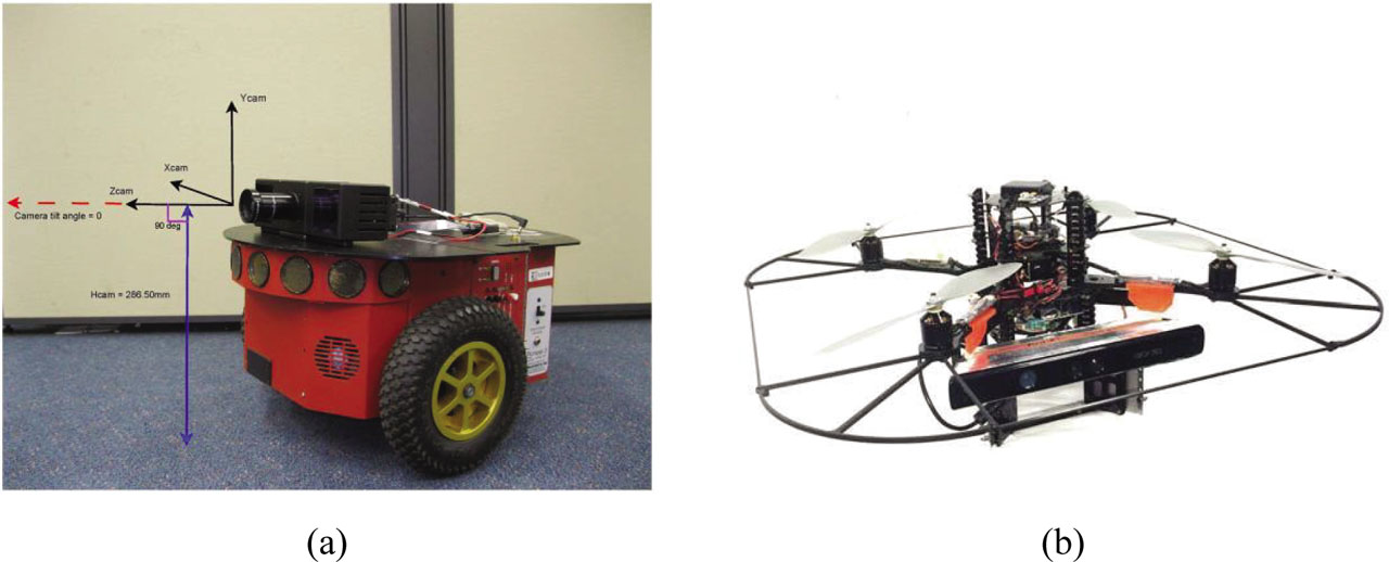
Figure 1:
System Overview. (a) PMD camera mounted on P3DX. (b) Microsoft Kinect mounted on the AscTec pelican quadrotor. P3DX, Pioneer 3DX.
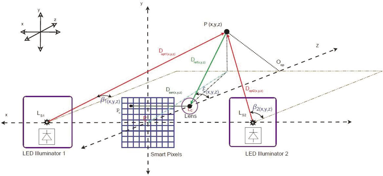
Figure 2:
Depth Camera Model.
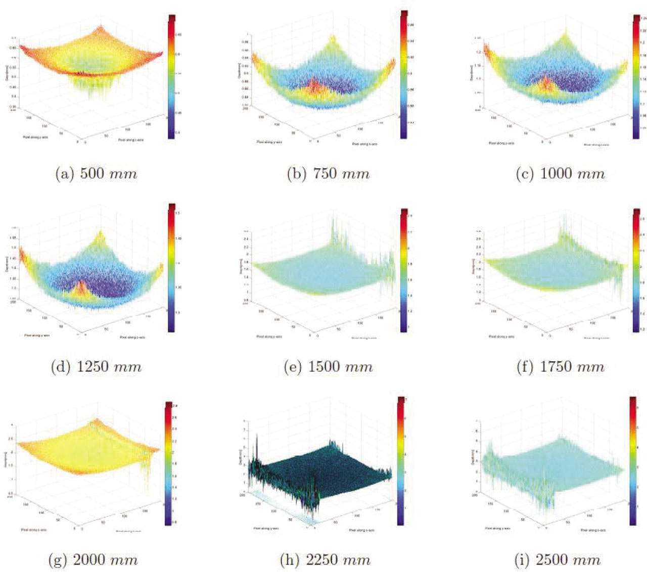
Figure 3:
PMD Depth Image Analysis with Barrel Distortions. The distance between the PMD camera and the fixed board are: (a) 500 mm (b) 750 mm (c) 1000 mm (d) 1250 mm (e) 1500 mm (f) 1750 mm (g) 2000 mm (h) 2250 mm (i) 2500 mm.
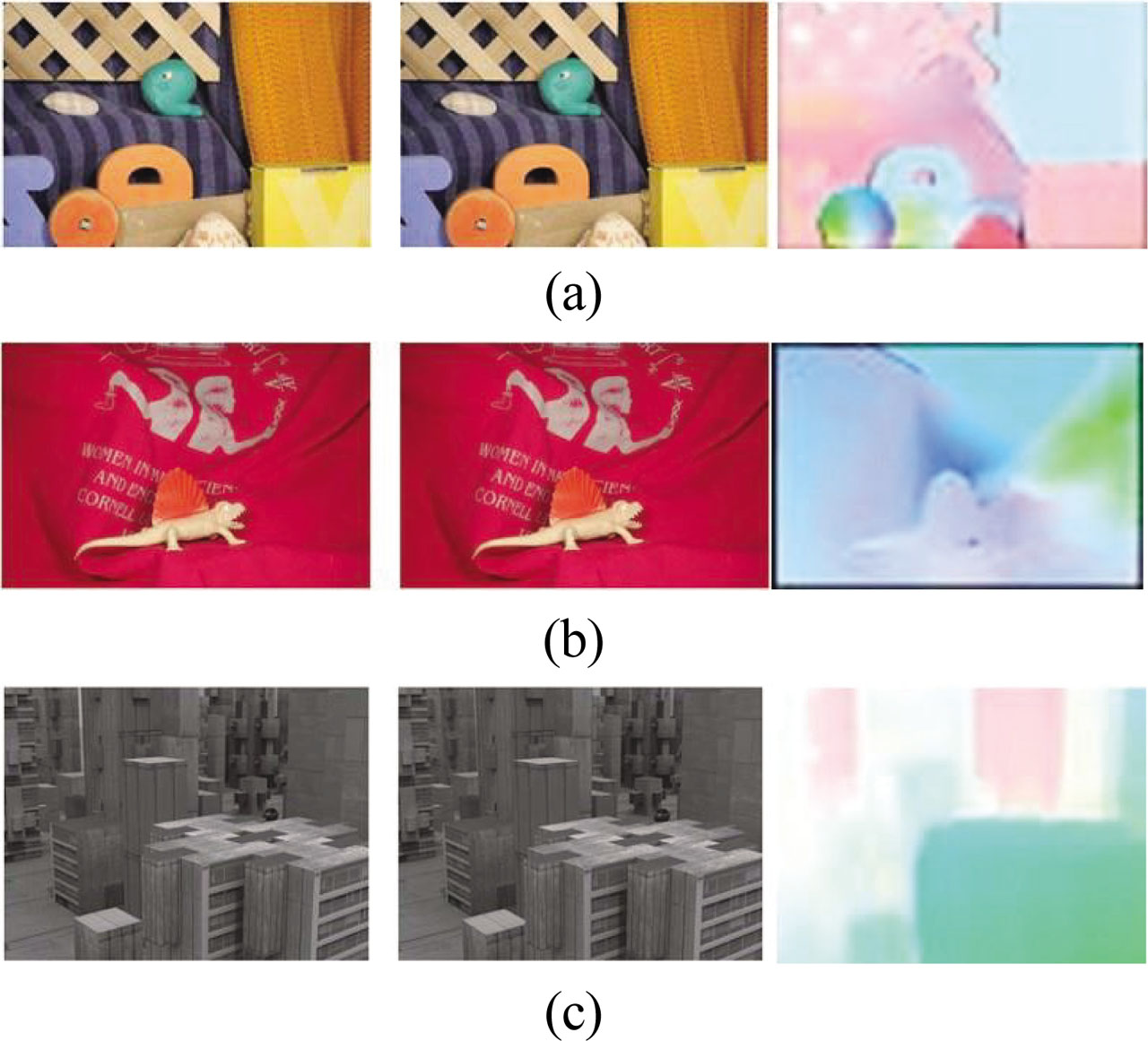
Figure 4:
Middlebury datasets: (a) Rubber Whale (b) Dimetrodon (c) Urban2.
Table 1.
Errors for Different Methods Compared with Middlebury Data Using MATLAB. [Regularization Parameter in GVF (μ = .01), Weighting Term (α = .01)]
| (μ = 0.01)(α = 0.01) | AAE | STDAE | EPE | AAE | STDAE | EPE | AAE | STDAE | EPE |
|---|---|---|---|---|---|---|---|---|---|
| Lukas–Kanade | 0.3128 | 0.25895 | 0.596 | 0.6691 | 0.3653 | 1.535 | 0.8884 | 0.5021 | 8.000 |
| Horn–Schunck | 0.3151 | 0.24985 | 0.603 | 0.7141 | 0.3602 | 1.625 | 0.9601 | 0.6128 | 8.038 |
| LK–HS | 0.3059 | 0.2625 | 0.586 | 0.6632 | 0.5202 | 1.627 | 0.8873 | 0.7030 | 8.064 |
| LK–HS–GVF | 0.3006 | 0.2585 | 0.576 | 0.6291 | 0.3086 | 1.526 | 0.8765 | 0.5381 | 7.870 |
[i] AAE, average angular error; EPE, endpoint error; STDAE, standard deviation angular error.
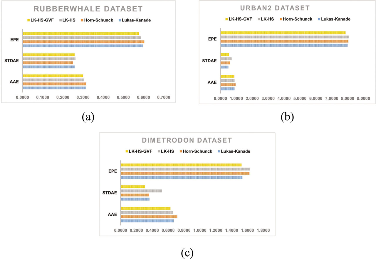
Figure 5:
Error Plots for Middlebury Datasets (a) Rubberwhale Dataset (b) Dimetrodon Dataset (c) Urban2 Dataset.
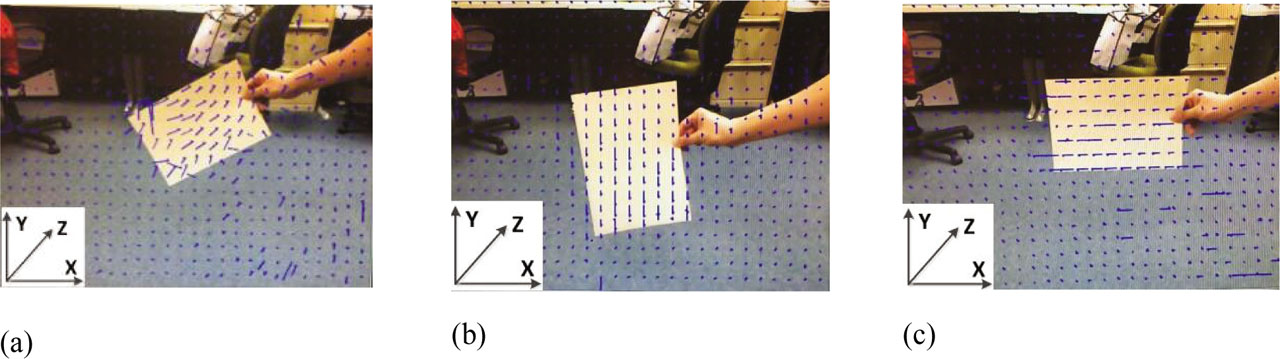
Figure 6:
Dense Scene flow in Various Directions (Bright Light); the Coordinate on the Bottom Left is the Camera Coordinate. (a) The x-flow and y-flow components are horizontal and vertical, respectively. To conduct this experiment, a 45º translation of the paperboard's x and y coordinates was made in the direction of the camera plane. (b) The z-flow component is horizontal, and the x-flow component is vertical. For this experiment, a combined motion in y and z coordinates was used to translate the paperboard in the direction of the camera plane. (c) The y-flow component is horizontal, and the z-flow component is vertical. To conduct this experiment, a combined motion in x and z coordinates was applied to the paperboard to translate it toward the camera plane.
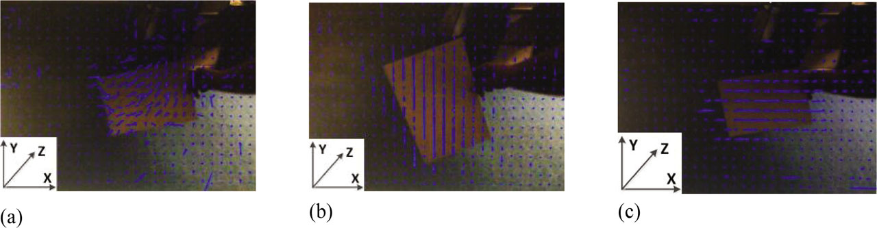
Figure 7:
The Camera Coordinate Is in the Lower Left Corner of a Dense Scene Flow in Various Directions with Partial Light. (a) The x-flow and y-flow components are horizontal and vertical, respectively. The paperboard was moved toward the camera plane while conducting this experiment with a 45º motion in the x and y coordinates. (b) The horizontal component is z-flow and the vertical component is x-flow. Doing this experiment, the paperboard was translated toward the camera plane with a combined motion in y and z coordinates. (c) Z-flow is the horizontal component, and x-flow is the vertical component. For this experiment, a combined motion in y and z coordinates was used to translate the paperboard in the direction of the camera plane.
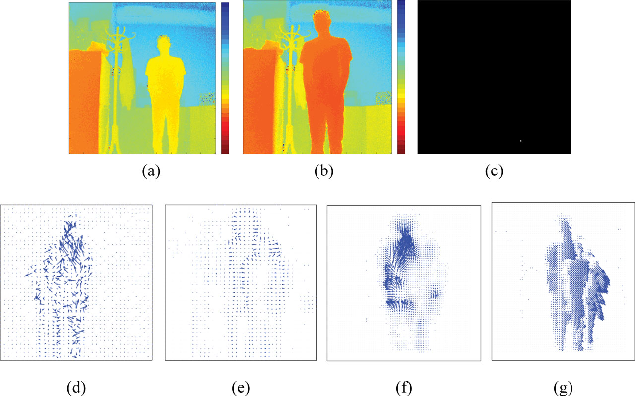
Figure 8:
Flow Vectors Are Shown with Close Objects Shown in Red and Far Objects Shown in Blue Using Various Methods. (a) Depth frame 1 with color coding. (b) Depth frame 2 with color coding. (c) Moving Obstacle Segmentation. (d) LK. (e) HS. (f) Combined Lk-HS. (g) Combined Lk-HS with GVF. GVF, gradient vector field; Lk-HS, Lucas–Kanade; Horn–Schunck.
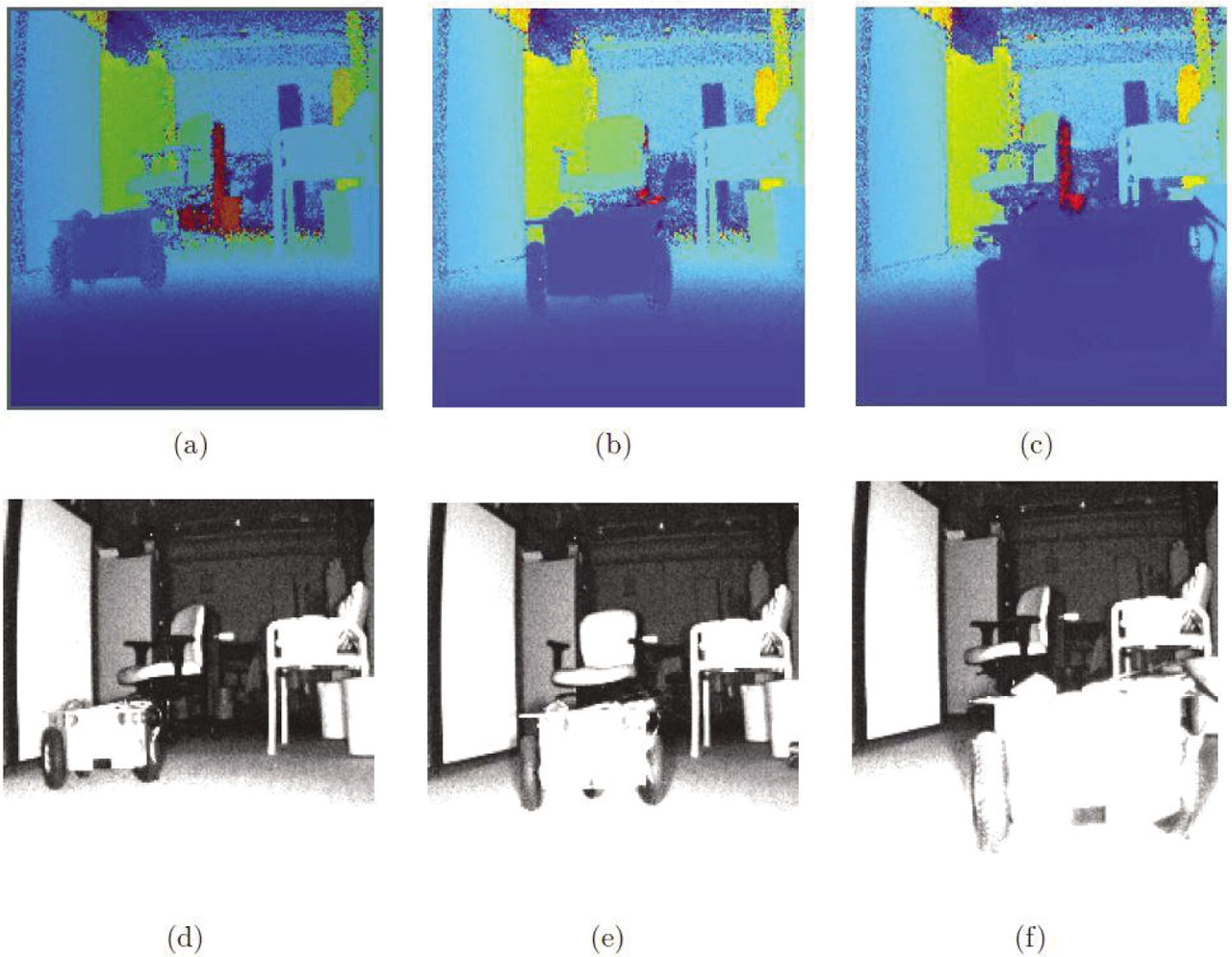
Figure 9:
Experiment I: (a–c) Range Images with 200 × 200 Pixels; (d–f) Grayscale Images.
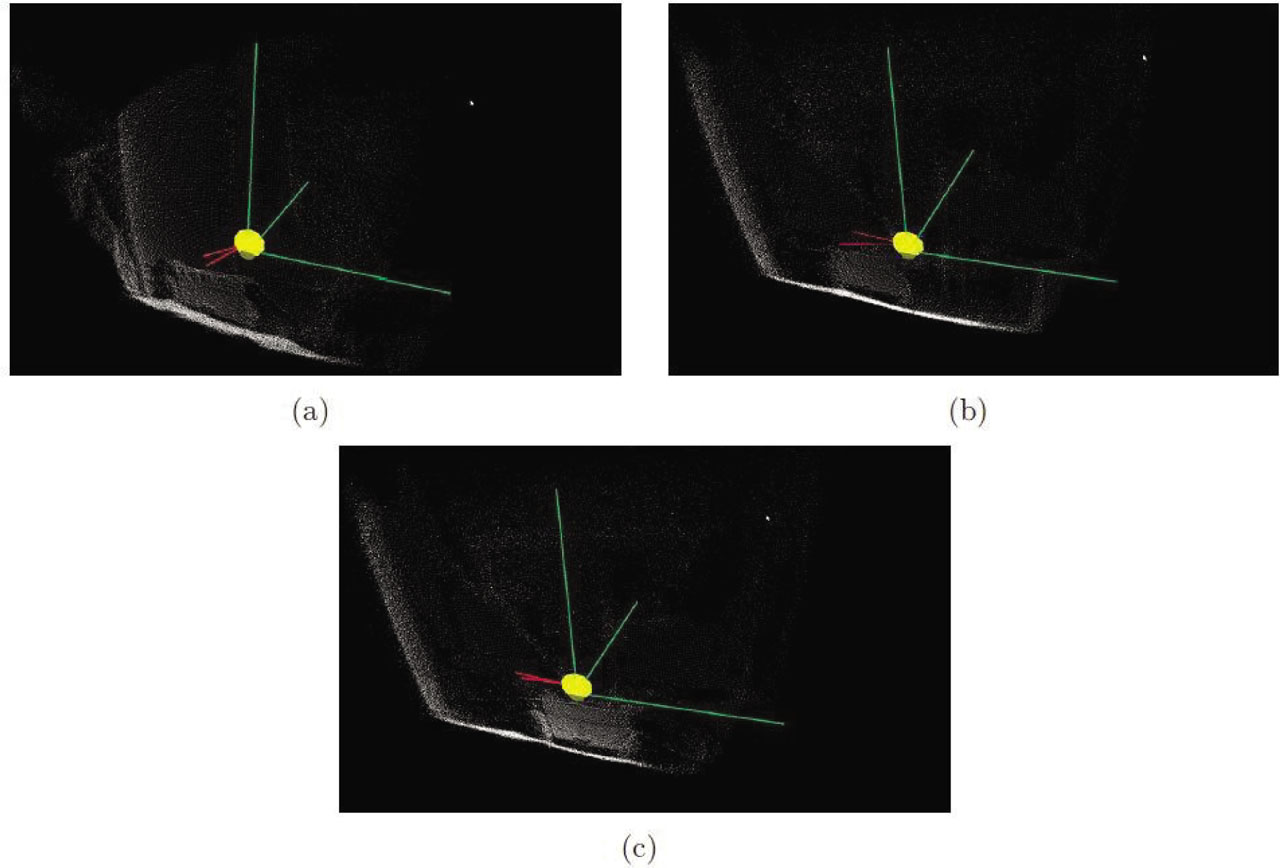
Figure 10:
Experiment I: 3D Renderings of PMD Camera on GLFW Window. (a) GLFW Frame 1.(b) GLFW Frame 2. (c) GLFW Frame 3.
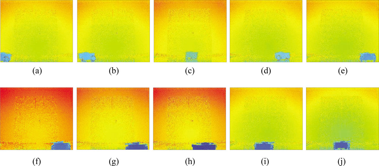
Figure 11:
Different Frames of a Moving Obstacle. (A–J) Frame 1 to Frame 10.
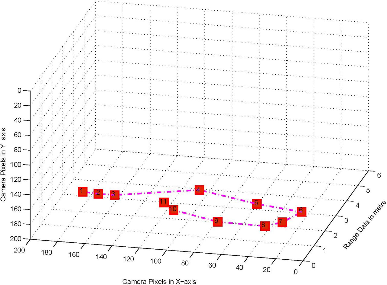
Figure 12:
Obstacle Position in 3D Plot.
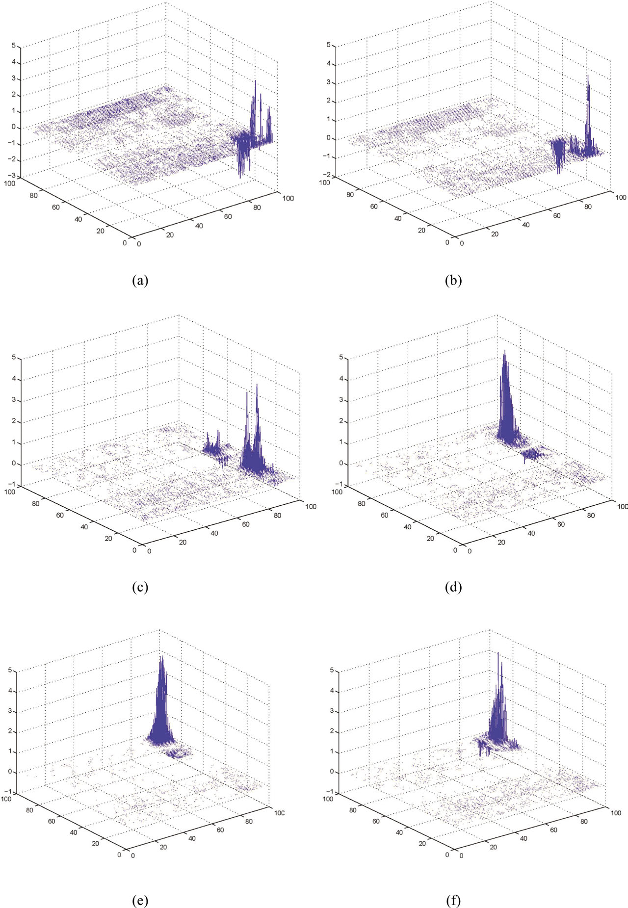
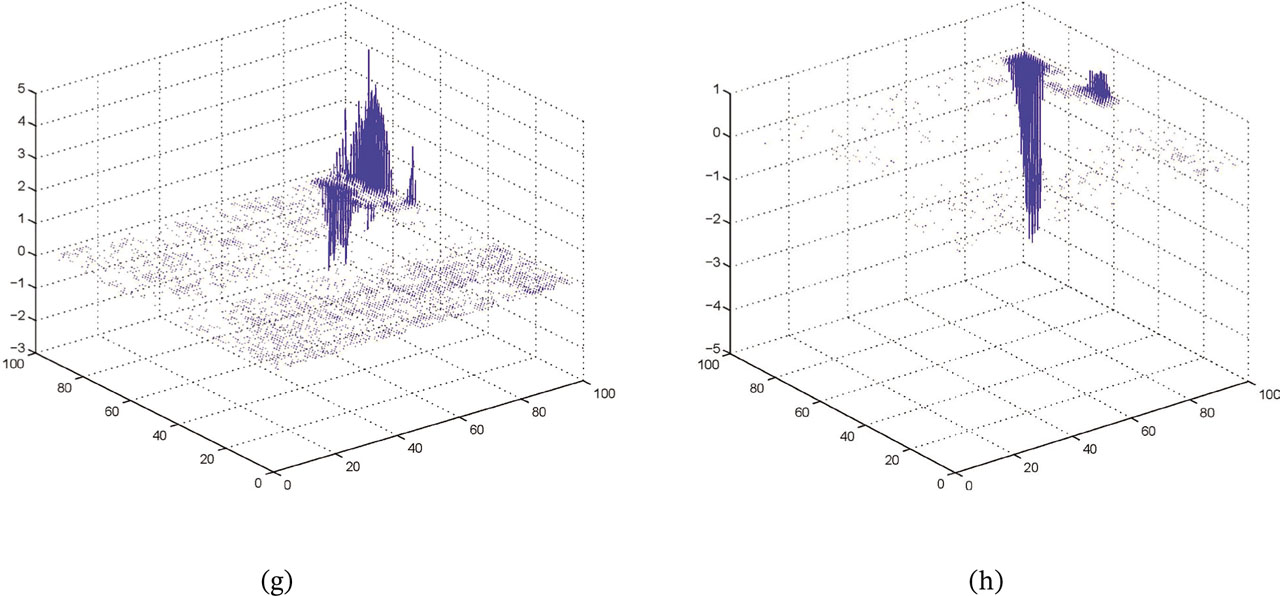
Figure 13:
Obstacle Segmentation: Dense Flow Vectors in 3D Plot.
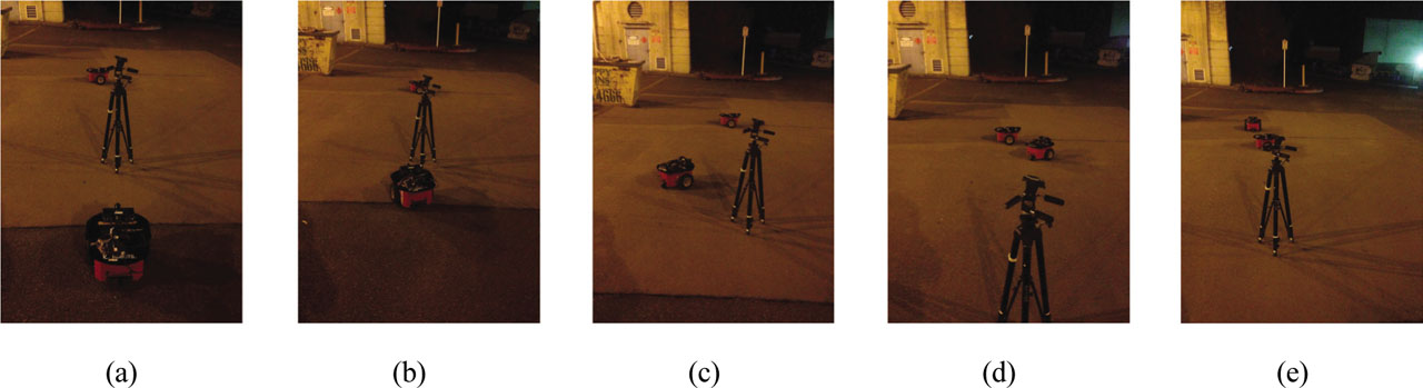
Figure 14:
Experiment II: Path Planning with Two Irregular Shaped Obstacles. (A–E) Frame 1 to Frame 5.
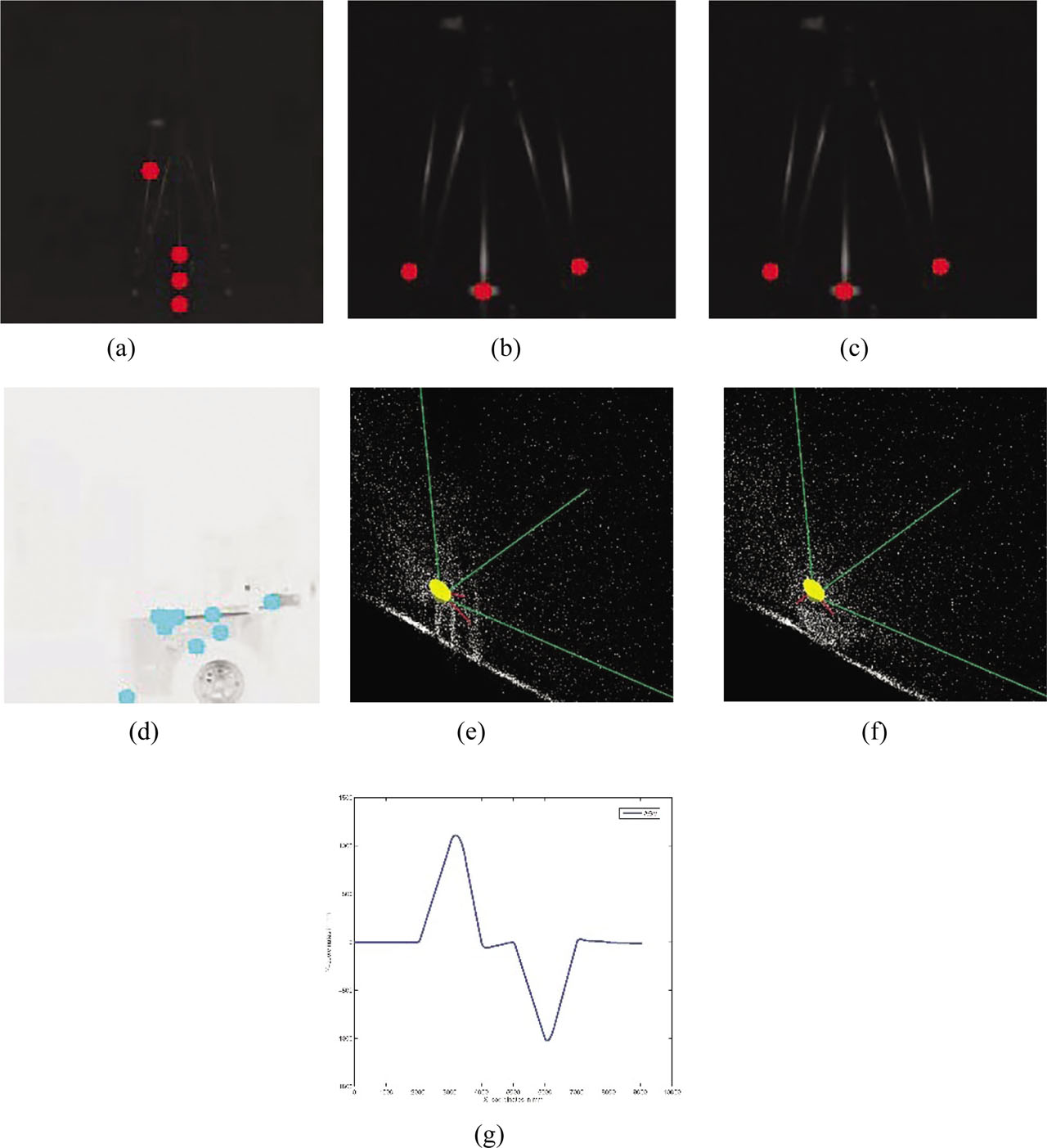
Figure 15:
Experiment II: Real-Time Rendering of PMD Range Data Using GLFW. (a) Range intensity: Tripod (far). (b) Range intensity: Tripod (near). (c) Range intensity: P3DX(2) (far). (d) Range intensity: P3DX(2) (near). (e) 3D point cloud of obstacle: tripod. (f) 3D point cloud of obstacle: P3DX(2). (g) Experiment II: plot of AGV's X-coordinates vs Y-coordinates. P3DX, Pioneer 3DX.
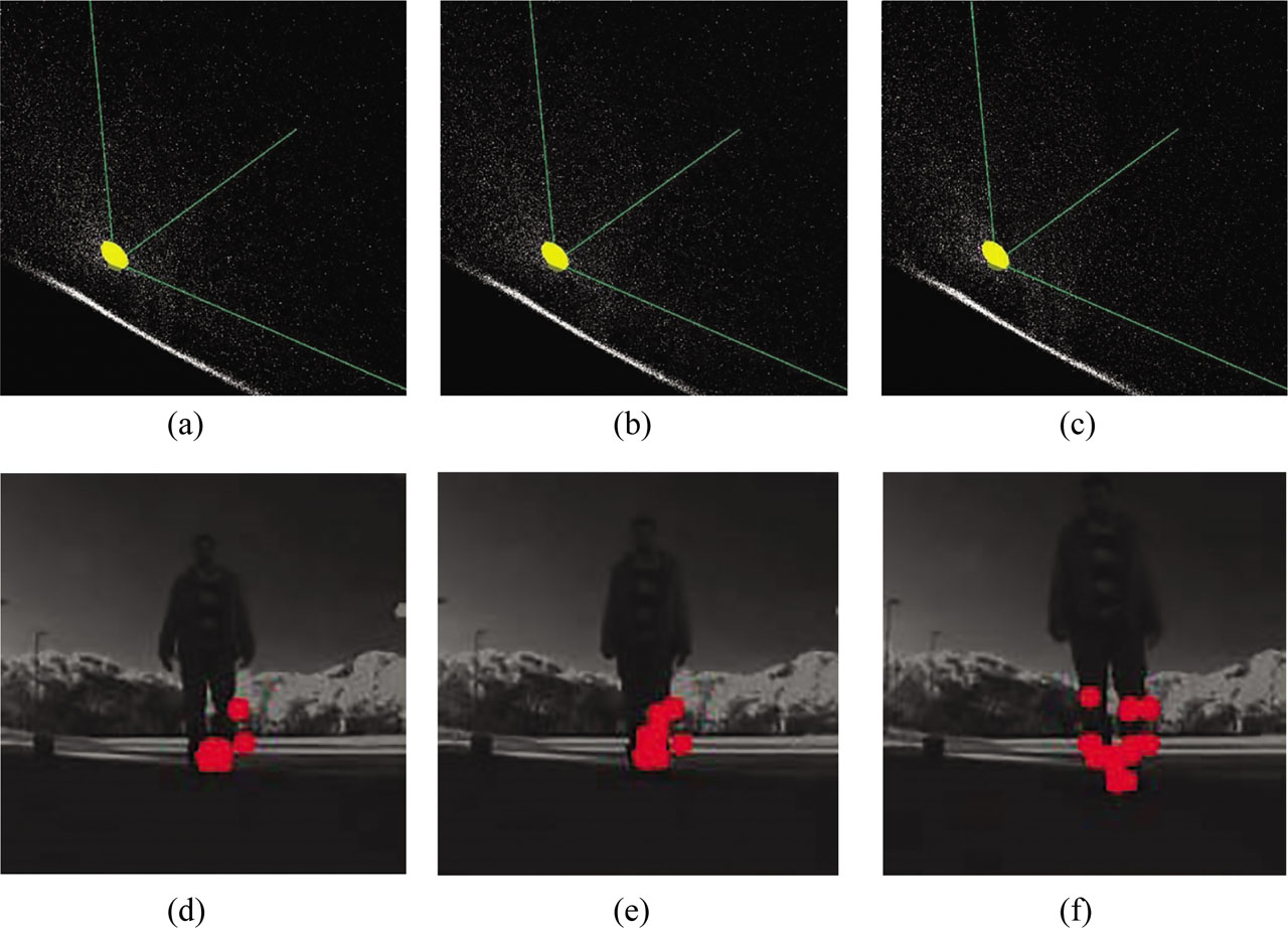
Figure 16:
Experiment III on Moving Obstacle: 3D Renderings of PMD Camera.