
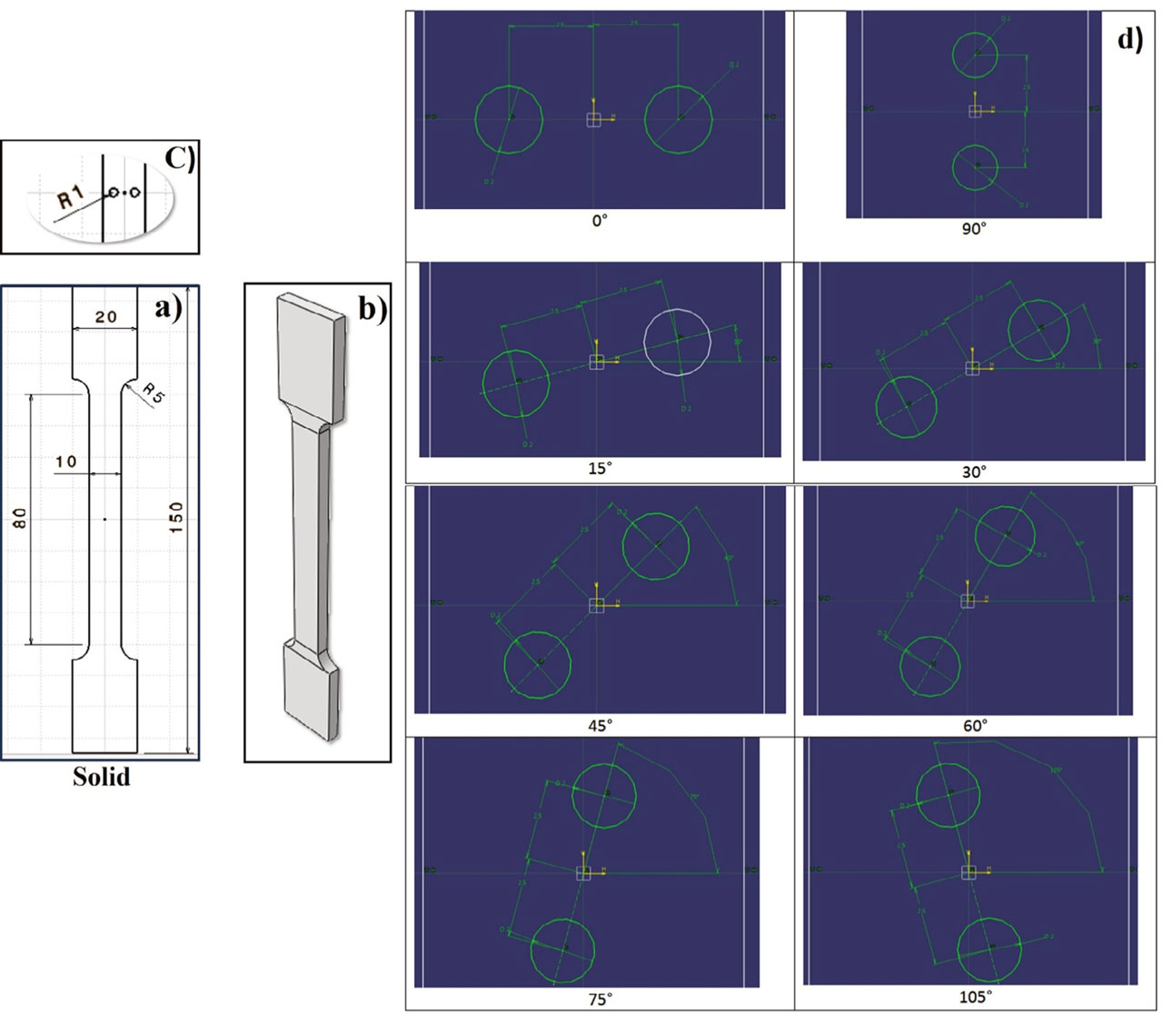
Fig. 1.
Specimen geometry and aperture-angle configurations: (a) solid (reference) specimen; (b) overall dog-bone dimensions of the test specimen, defined according to ISO 3167:2014(E), with gauge length L0, gauge width b, and thickness h; (c) detail of the gauge section showing the two through-thickness apertures of equal radius R1 and inter- center spacing d, with the angle θ measured between the inter-center line and the axis transverse to the loading direction; (d) the eight aperture orientations investigated (θ = 0°, 15°, 30°, 45°, 60°, 75°, 90° and 105°) together with the solid reference.
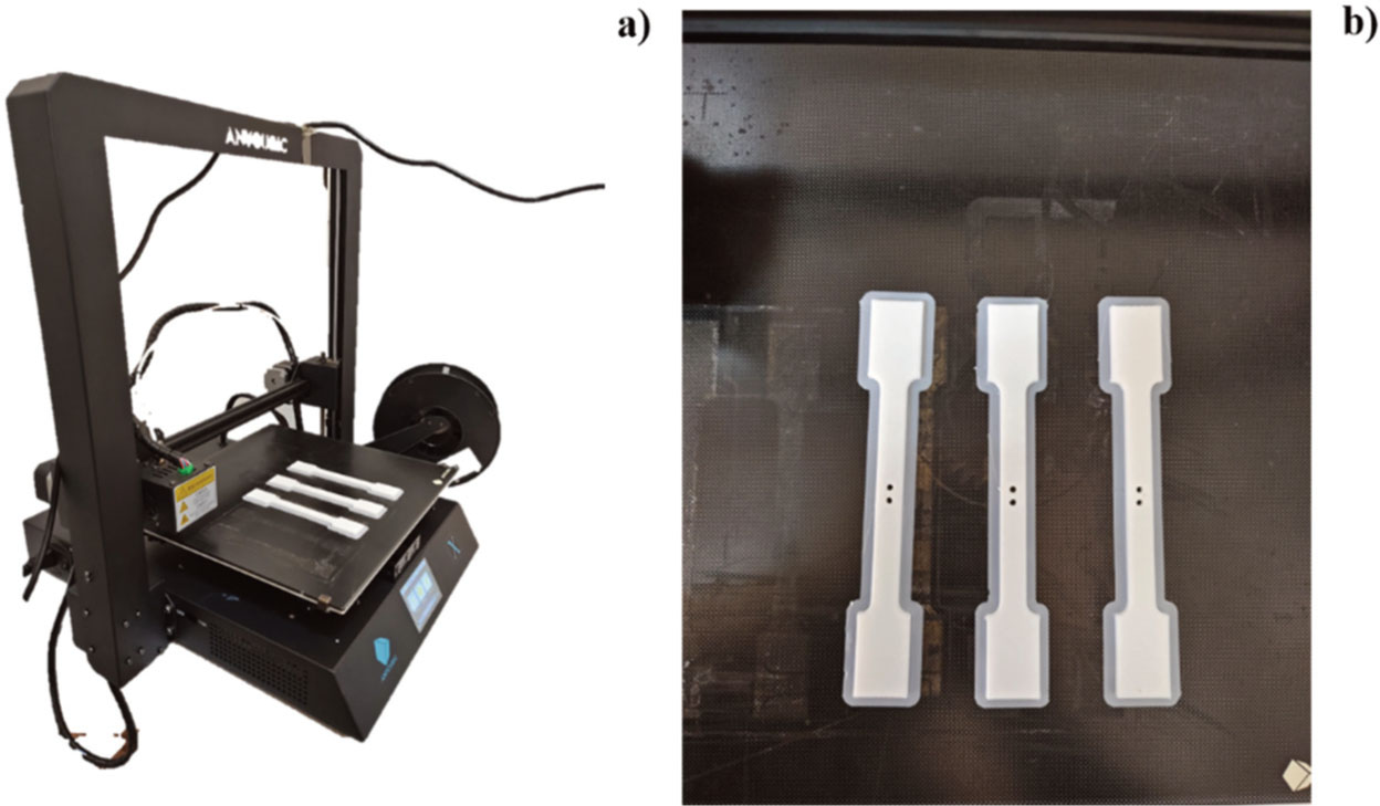
Fig. 2.
Specimens during and after printing. (Source: authors’ own work).
Table 1.
Filament specifications and FDM print parameters held constant across all 27 specimens.
| Parameter | Symbol | Value | Unit |
|---|---|---|---|
| Filament material | — | PLA, white | — |
| Filament diameter | df | 1.75 | mm |
| Filament density | ρ | 1.24 | g/cm3 |
| Spool weight | — | 1 | kg |
| 3D printer | — | Anycubic i3 Mega X | — |
| Nozzle temperature | Tn | 200 | °C |
| Build-plate temperature | Tb | 60 | °C |
| Layer height | hl | 0.20 | mm |
| Wall thickness | tw | 1.20 | mm |
| Infill density | ρinf | 100 | % |
| Infill / raster pattern | — | Rectilinear, ±45° | — |
| Print speed | v | 50 | mm/s |
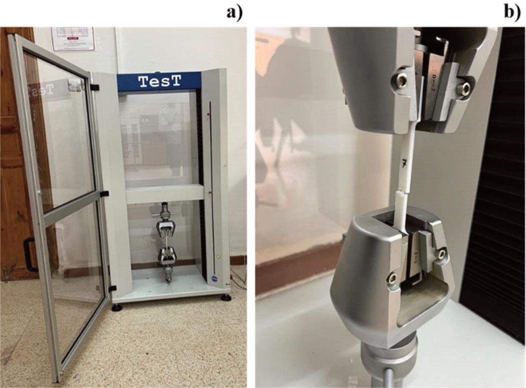
Fig. 3.
Tensile testing protocol. (Source: authors’ own work).
Table 2.
Summary of experimental σnom,max results for all nine configurations.
| θ | σnom,1 (MPa) | σnom,2 (MPa) | σnom,3 (MPa) | Mean σnom,max ± SD (MPa) | Anet/A0 (–) | Regime | Mean σnet,max (MPa) | % red. in σnom |
|---|---|---|---|---|---|---|---|---|
| Solid | 28.24 | 25.51 | 27.96 | 27.23 ± 1.50 | 1.000 | — | 27.23 | — |
| 0° | 24.48 | 23.87 | 22.65 | 23.67 ± 0.94 | 0.600 | Two-hole-cut | 39.45 | +13.1 |
| 15° | 21.87 | 23.19 | 21.68 | 22.25 ± 0.82 | 0.695 | Two-hole-cut | 32.01 | +18.3 |
| 30° | 24.12 | 23.92 | 25.94 | 24.66 ± 1.11 | 0.800 | One-hole-cut | 30.83 | +9.4 |
| 45° | 24.85 | 23.97 | 23.57 | 24.13 ± 0.65 | 0.800 | One-hole-cut | 30.16 | +11.4 |
| 60° | 25.97 | 26.27 | 25.52 | 25.92 ± 0.37 | 0.800 | One-hole-cut | 32.40 | +4.8 |
| 75° | 26.71 | 26.40 | 26.55 | 26.56 ± 0.15 | 0.800 | One-hole-cut | 33.20 | +2.5 |
| 90° | 27.55 | 27.65 | 27.08 | 27.42 ± 0.30 | 0.800 | One-hole-cut | 34.28 | −0.7 |
| 105° | 28.07 | 28.95 | 26.92 | 27.98 ± 1.01 | 0.800 | One-hole-cut | 34.98 | −2.8 |
Table 3.
Summary of Eapp results for all nine configurations.
| Aperture Angle | E1 (MPa) | E2 (MPa) | E3 (MPa) | Mean (MPa) | SD (MPa) | R2 (all) |
|---|---|---|---|---|---|---|
| Solid | 1437.0 | 1442.2 | 1442.0 | 1440.40 | 2.96 | >0.999 |
| 0° | 1308.8 | 1411.1 | 1372.4 | 1364.08 | 51.61 | >0.999 |
| 15° | 1446.7 | 1483.5 | 1457.7 | 1462.64 | 18.87 | >0.999 |
| 30° | 1453.1 | 1436.2 | 1435.9 | 1441.75 | 9.86 | >0.999 |
| 45° | 1445.3 | 1448.0 | 1450.1 | 1447.77 | 2.43 | >0.999 |
| 60° | 1448.5 | 1454.7 | 1451.5 | 1451.56 | 3.10 | >0.999 |
| 75° | 1460.2 | 1408.6 | 1447.5 | 1438.76 | 26.86 | >0.999 |
| 90° | 1453.2 | 1466.0 | 1445.0 | 1454.72 | 10.59 | >0.999 |
| 105° | 1496.4 | 1501.4 | 1485.8 | 1494.49 | 7.97 | >0.999 |
| Overall Mean | — | — | — | 1444.02 | 37.53 | >0.999 |
Table 4.
Representative specimens selected for FEA validation. The representative specimen of each group is the one whose σnom,max lies closest to the group mean.
| Aperture Angle | Specimen | Specimen σnom,max (MPa) | Group mean σnom,max (MPa) |
|---|---|---|---|
| Solid | SP3 | 27.96 | 27.23 |
| 0° | SP5 | 23.87 | 23.67 |
| 15° | SP7 | 21.87 | 22.25 |
| 30° | SP10 | 24.12 | 24.66 |
| 45° | SP14 | 23.97 | 24.13 |
| 60° | SP16 | 25.97 | 25.92 |
| 75° | SP21 | 26.55 | 26.56 |
| 90° | SP22 | 27.55 | 27.42 |
| 105° | SP26 | 28.07 | 27.98 |
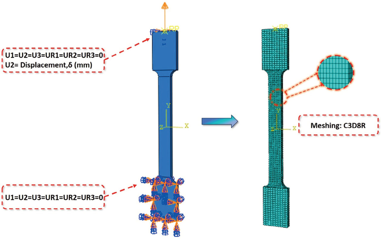
Fig. 4.
Loading and meshing parameters. (Source: authors’ own work).
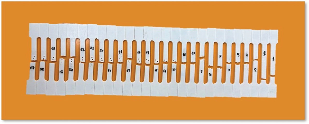
Fig. 5.
All 27 specimens after tensile test.
(Source: authors’ own work).
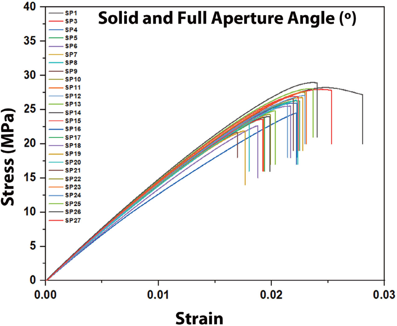
Fig. 6.
Stress–strain behavior in 27 experimental specimens.
(Source: authors’ own work).
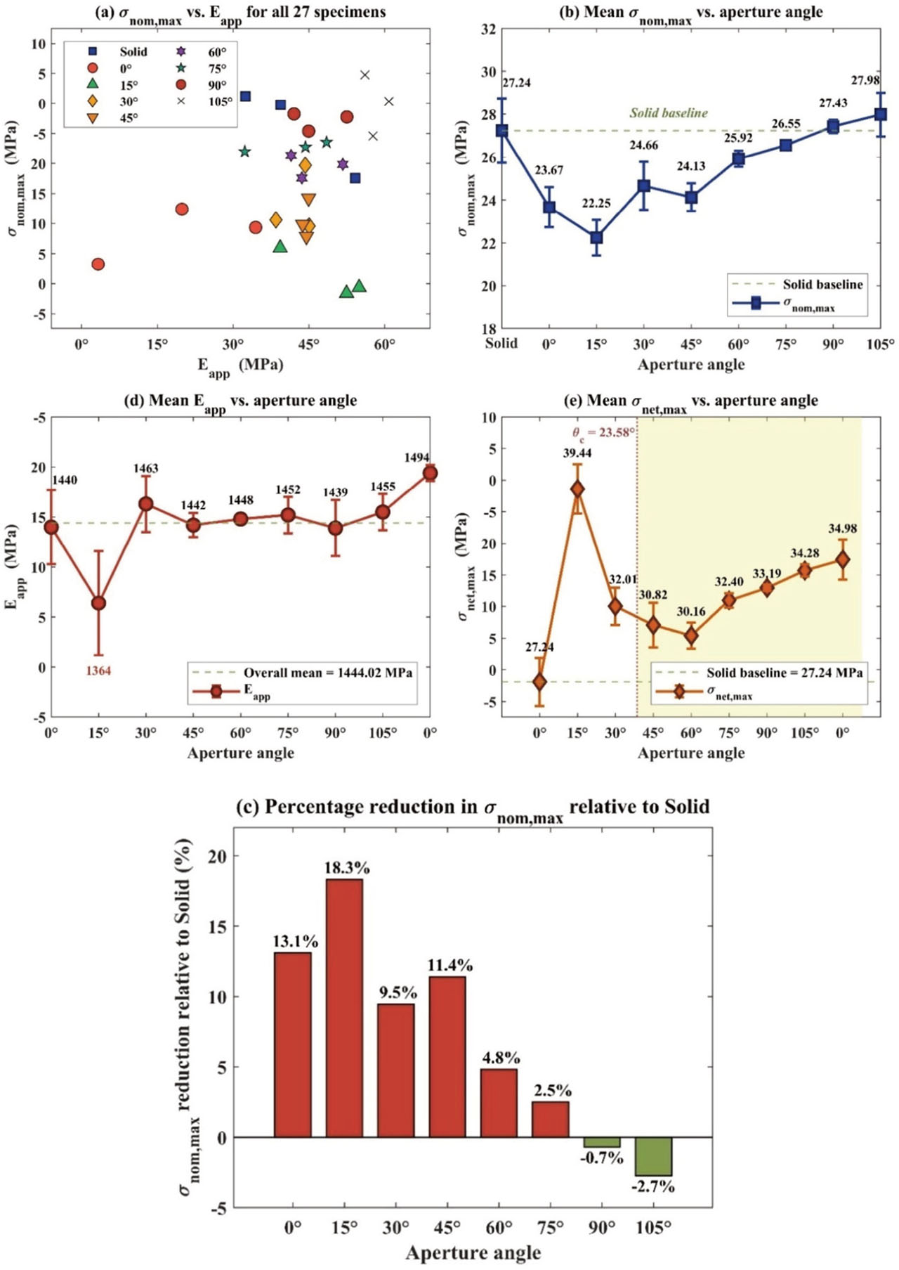
Fig. 7.
Comprehensive mechanical properties analysis: (a) σnom,max vs. Eapp scatter plot for all 27 specimens, (b) Mean σnom,max variation with aperture angle, (c) Percentage reduction in σnom,max relative to solid configuration, and (d) Mean Eapp variation with aperture angle. (Source: authors’ own work).
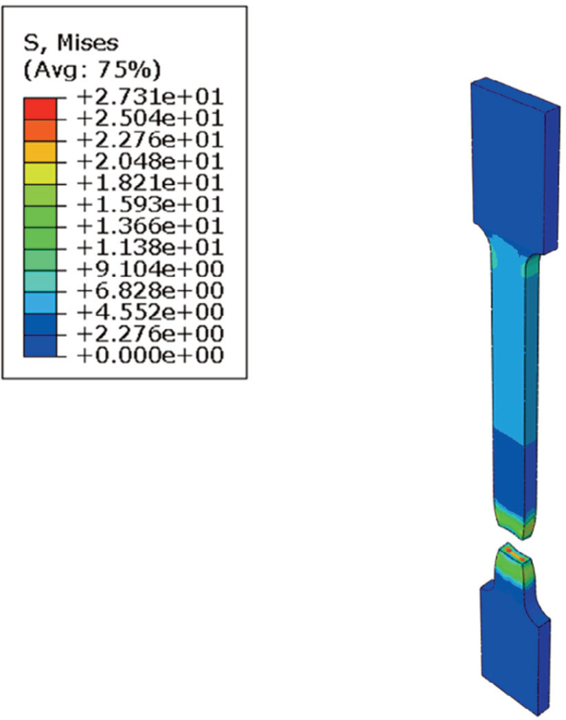
Fig. 8.
Finite element prediction of von Mises stress field and fracture at σnom,max for solid specimen. (Source: authors’ own work)
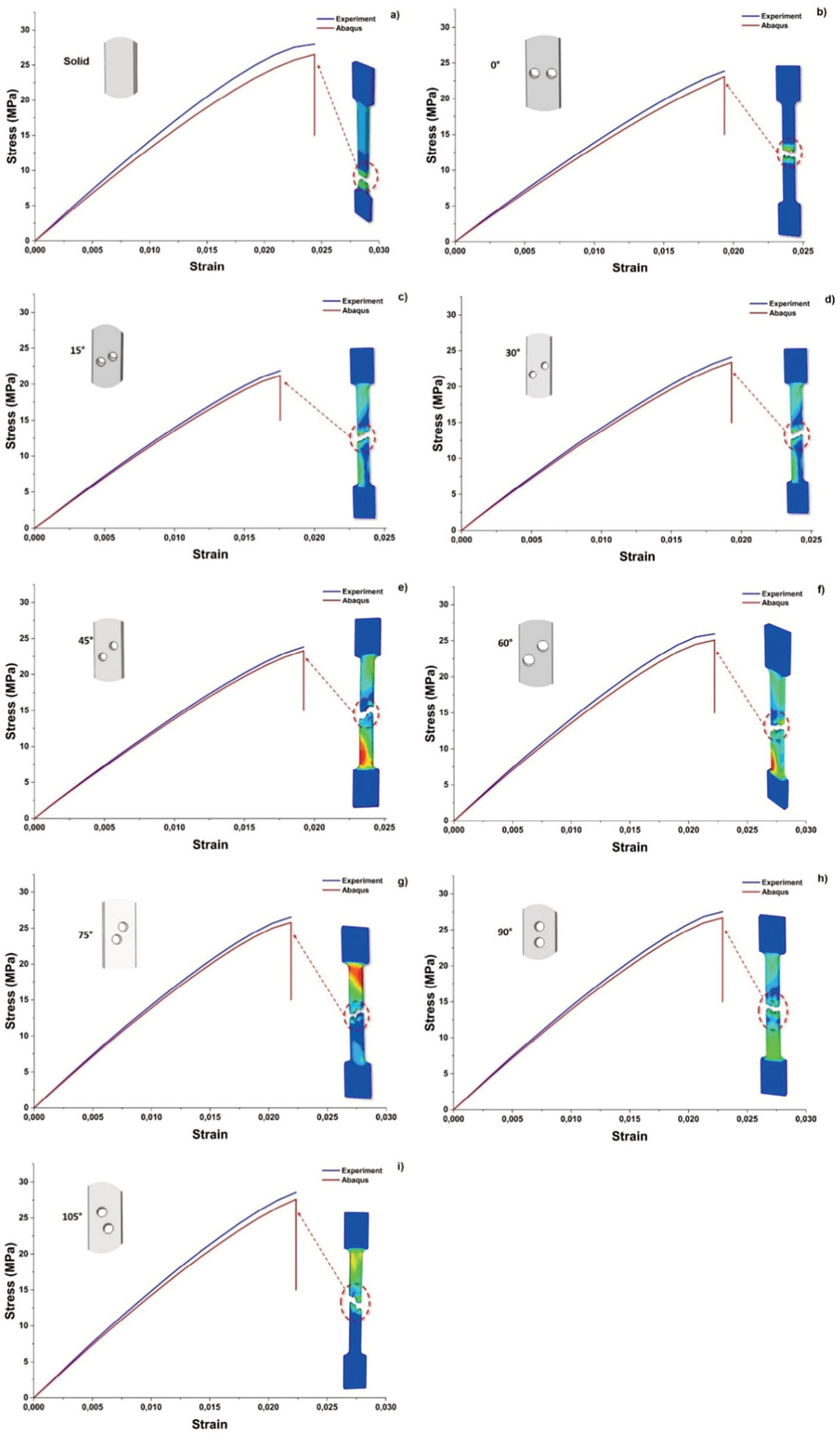
Fig. 9.
Comparison of experimental and FEA stress–strain curves for representative specimens: (a) Solid, (b) 0°, (c) 15°, (d) 30°, (e) 45°, (f) 60°, (g) 75°, (h) 90°, (i) 105°. (Source: authors’ own work).