

1. Introduction
As demands of modern architectural design evolve and the needs of construction projects run in depth, straightness is no longer the only option for concrete members, nor can it be considered a good choice in all cases which more often than not the traditional pathways of structural elements like lintels need to be compromised for either functional or architectural reasons. Current trends in architecture aim to find the appropriate balance between visual appearance and structural efficiency, this has led designers to use variable-path beams to improve the aesthetics of buildings or address conflicts with other components, such as mechanical systems (i.e., conduits and pipes). In addition, this kind of structure modification might happen when the number of columns is reduced or open spaces are enlarged, also known as internal column removal which usually happens in low-rise and medium rise buildings (Arafah 2000). The strike will make itself clear on numerous prominent world applications, for example, the Tokyo Sky House design; The Budapest transport stations and complex building developments in China are fruitful examples of various way solid lintels. Changing the path method by a concrete beam from a structural point of view, this is not just an alteration in the geometry of the element is to form a set of stresses within it as if being exposed to more than one type with support loading (bending moments, axial forces, torsional moments, and shear forces). So, beams with out of plane parts which is a RC beam made up of straight segments connecting points where the axis change direction abruptly and forming a zigzag path. Unlike curved beams, the axis varies continuously along the beam with no sudden direction changes; unlike offset beams, which are not bent but simply have constant eccentricity shifted laterally or vertically (and remain essentially straight); and different from geometrically irregular beams in general (i.e. tapered / haunched beams) that alter flexural stiffness without producing the coupled shear-torsion--flexure coupling signature of OPBs at their connection zones. The complex behaviour of this type of structure requires a detailed study of beam behaviour and proper understanding on load transfer, crack propagation and possible weak points, it makes the analysis and design of these beams an important topic in engineering. As such, many researchers investigated the structural behaviour of RC beams under coupled shear, bending, and torsion loads (Owainati 1973). The impact of combined loading on the RC beams’ behaviour was studied by (Owainati 1973), where the behaviour was affected by varying the ratio of main and transverse steel reinforcement under different types of loading configuration. The results showed that the type of load influenced both the failure mechanism and shape of the crack. The increase in steel ratio also produced the highest strengthening for torsional strength and cracking resistance, compared to other parameters. Shear, flexural and torsional behaviour were investigated for the RC floor-to-Spandrel beam under various loading configurations (Ali and Anis 1983) both theoretically and experimentally. For the combined loads, the results indicated that the ductility of the member was greatly diminished. Also, with an increase in the angle of the load, torsional stresses appeared. (Kamiński and Pawlak 2011) investigated experimentally and numerically the behaviour of RC beams subjected to couple loading. The outcomes revealed that the utilization of combined torsional, bending and shearing forces decreased the stiffness of RC beams. (Elsayed et al. 2015) studied the effect of changing cantilever’s inclination angle on the reinforcement ratio of RC beams). The study found that increasing the angle of the relocation steel reinforcement does not affect the ultimate level load, cracking nor stiffness appreciably but possessing a very positive torsional effect on RC beams. Combination loading was carried out on the fixed-end RC beams by (Rafeeq 2016). The study found that constraining it by the torsion shear in addition to bending caused a drop in its torsional and bending strengths. Research done by (Amulu and Ezeagu 2017) investigated the response of normal-strength reinforced concrete beams subjected to mixed loadings including torsion moments, bending moment and shear forces. In this research, standard design codes and experiments were applied to conclude that the failure of beams was due to an interaction between torsional force, shear force and bending moment. Your capacity to sustain the total imposed loads was enhanced via improved ratios of longitudinal and transverse reinforcement in these beams. Helpful in that the combined loads on a beam with suggest from torsion design mode enough of reinforce, at least for shear and bending. This indicated that the beams could be designed to be increasingly resistant to the effects of combined loading. This work focused on the behaviour of out-of-plane beams reinforced with GFRP bars, delving into both mono- and hybrid-fibre arrangements (Jasim and Al-Azzawi 2024). The researchers used a nonlinear, three-dimensional finite element model to study the effects of fibres (monofilament and hybrid) on the member reinforcement for beam members subjected to out-of-plane lateral loading. The study concentrated on the mechanical characteristics of concrete beams reinforced with GFRP and performed multi-load simulations to evaluate the impact of fibre parameters, including fracture, plastic deformation, and crack propagation. The results showed that the hybrid fibres reduced the out-of-plane bending deformations by approximately 20–35% (compared to beams reinforced with only one type of fibre) and also enhanced ultimate load resistance and crack propagation. (Sayed et al. 2025) investigated on how the out of plane distance in lateral direction at mid-span to a steel beam influences its sectional moment capacity. This study focused on how the out-of-plane lateral distance at the mid-span of a steel beam affected its moment-resistance capacity. Using numerical analysis and finite element modelling, the researchers modified displacement horizontally at the mid-span of member from 0 to O.2 beam width. It was found, by increasing this translation, the ultimate moment capacity decreased up to 25–40%, together with a significant decrease in moment stiffness. The study also compared ABAQUS models with the analytical predictions, obtaining agreement within 5%. Depending on the displacement speed versus beam width, the effect is proportional; these effects must be Considered in designing any steel member experiencing out-of-plane conditions (such as at intersections or locations under a concentrated load), the researchers cautioned. (Muhammed et al. 2024) presented an experimental study concerning the behaviour of RC beams under two-point load with different out-of-plane parts. The study included five reinforced concrete beams (150×200×2000 mm) loaded with two centre points taken from the beam elements containing different out-of-plane lateral parts. The study investigated the effect of varying the span of these beams (150 and 300 mm) and the use of high-strength steel on their behaviour. The results showed that the presence of an out-of-plane part reduced the ultimate load by approximately 80% compared to a straight beam. The 300 mm-long part exhibited purely torsional behaviour, while the 150 mm-long part exhibited a mixed behaviour of bending and rotational sliding. Adding rotational shear-resisting reinforcement improved the ultimate strength by ∼80% for the 300 mm section, but its effect was limited (∼5%) for the 150 mm section. Although a significant amount of research has been carried out on RC beams subjected to combined loading, there is still a lack of information regarding the simultaneous effects of segment number, concrete strength, and embedded steel section on OPB structural behaviour. Prior investigations have typically evaluated these parameters in isolation, not considering how their interaction affects the shear, torsional and flexural response, nor how it dictates the failure/transfer of stress from segment to segment as each is oriented differently. In contrast to previous studies, which typically focused on the behaviour of RC beams subjected to a single and dominant loading mode or considered straight (in-plane) beam geometry with multiple load directions but not the same combinations, this study innovatively included shear and torsional moments in conjunction with flexural actions for out-of-plane beams (OPB), a beam configuration that has received scant attention in literature. This study investigates the joint failure mechanism and failure modes of OPB beams as well as combined stress transfer across the beam segments and cross-sectional development associated with a change in segment direction. This study presents a novel finite element (FE) modelling method that considers the composite action of steel and concrete components in different segment directions, which have not been considered by previous numerical studies. The most significant aspect of the current study as compared to previous studies on performance of RC beams are the use of composite nature & nonproportionality in failure behaviour by using geometric segmentation, composite action, and Issue into load or deformation mode (or path). Figure 1 illustrates the application of OPB beams in various structures.
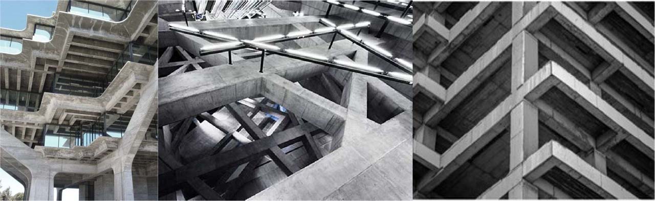
Figure 1:
Beam with out-of-plane parts applications
2. Finite Element Modelling
ANSYS APDL software was utilized to generate a dimensional finite element model for the purpose of conducting research on the behaviour of the concrete beams. With the help of the finite element method, the researchers were able to gain an understanding of how beams that out-of-plane parts behave. Through the utilization of this strategy, one can acquire a wide range of superior results. Based on the comparison between the experimental and numerical results, it was determined that the FE somewhat overestimated the stresses. This was due to the fact that the concrete was more homogeneous in the FE’s numerical analysis than it actually was. The results of the finite element analysis (for example, cracking load, ultimate load, deflection, and so on) were comparable and precise enough when compared to the experimental work. Specifically, the finite element method (FEM) that was discussed before is utilized in this instance to implement the OPB beams. Three groups of research demonstrate how different characteristics influence the behaviour of OPB beams. These sets are organized through the studies. Straight RC beams were utilized in the first set of experiments; however, in the second and third sets of tests, which investigated the number of connecting segments and their placement, eight specimens were employed, with four models in each set. These specimens were made from out-of-plane sections of concrete beams. In accordance with this hypothesis, concrete is not a material that is uniform since the linear and nonlinear properties of the material vary when it is subjected to tension and compression (Hashim et al. 2023; Zhu 2001). The mechanical characteristics and behaviour of concrete have been the subject of several investigations that have been conducted over the years. The same behaviour can be accurately and concretely modelled in FE ANSYS. The sensitivity of the concrete element in FE packages makes it tough to represent concrete in the form of beams with diverse configurations (Abdulghani and Jaafer 2021). The most important state in concrete behaviour is the brittleness of this element. This study takes into account the modelling of a beam that has a unique configuration, namely a beam without flat components, and gives the results of that analysis. The concrete beam component’s behaviour and materials must be defined in the OPB beam model. The failure theory of each material determines how the concrete, steel reinforcement, and sections behave. To illustrate how concrete and steel behave, a plastic-damage constitutive law was employed. The effectiveness of the damage constitutive rule in accurately characterizing the nonlinear behaviour of concrete and identifying the specific failure mode is first supported by experimental findings on concrete beams (Bhavikatti, 2005). Its mechanical properties and behaviour have been the subject of several studies that have been conducted throughout the years. Additionally, FE ANSYS can accurately and concretely model the described behaviour. Because the concrete element is so sensitive in FE packages, however, it is still difficult to simulate concrete in the shape of beams with varying configurations (Roylance, 2001), (Abbu et al., 2013), and (Abbu et al., 2014). Important to the concrete’s behaviour is the element’s brittleness. In this study, we give the results of an examination of a beam that models a beam with a unique configuration, one that does not have any plane components. When doing OPB beam modelling, it is necessary to specify the material and behaviour of the concrete beam component, the latter of which is dependent on the failure theory of the reinforcing steel and the concrete itself. The concrete and steel behaviours were represented by a plastic-damage constitutive law. First, experimental data on concrete beams corroborate the efficacy of the damage constitutive rule in explaining the nonlinear behaviour of concrete and capturing the specific failure mechanism (Lee and Fenves 1998). The structural capacities of the OPB beams must be validated by a Finite Element Analysis (FEA). This is accomplished with the help of the program ANSYS APDL. To ensure accuracy, researchers from several universities compare the FEA-generated load-displacement relationships, maximum loads, deflections, and failure modes to the outcomes of their experimental tests. Research often makes use of a multi-element finite element model, as illustrated in Fig. 2. The mesh is improved so that the complex joint geometry may be more accurately represented, and the input values are adjusted such that convergence requirements are always satisfied. Using the convergence criterion, we may check how accurate and reliable the analysis is. A lack of convergence was seen in this case when the values of the open and close shear transfer coefficients fell below 0.2, suggesting that some tweaks were necessary (Lubliner, 1989). However, when there were more than 13,142 elements, optimum alignment was reached.
3. Material Modelling
3.1. Modelling of Concrete, Steel section, and Rebar
To represent concrete in ANSYS, one must first define the material properties that distinguish between compression and tension and capture its quasi-brittle behaviour. Until the yield point is reached, the stress-strain curve of concrete usually behaves linearly in tension and compression. Cracks form and strength decrease after yielding concrete, eventually leading to crushing failure. The fissures will keep expanding until they are as wide as they can get. The curve enters the softening region and eventually breaks when the maximum strain is attained. A reduction factor of stiffness, modulus of rupture, ultimate uniaxial compressive and tensile strengths, elastic modulus (E), and Poisson’s ratio are some of the material parameters used to determine concrete behaviour in ANSYS (Handhal et al. 2023). In the case of tension, concrete exhibits a relatively different behaviour. Stress increases with strain in an almost linear fashion until the concrete reaches its ultimate tensile strength. Upon reaching this stage, cracks begin to appear within the concrete mass, leading to a rapid decrease in its tensile strength due to crack propagation and loss of internal cohesion, until its stress-bearing capacity becomes very low (Kachlakev et al. 2001). To represent the behaviour of concrete in numerical analysis using ANSYS software, a set of fundamental properties that express the mechanical behaviour of the material must be defined. These properties include the compressive strength of the concrete, tensile strength (modulus of rupture), modulus of elasticity (E), Poisson’s modulus (µ), and the stress reduction coefficient after cracking. In the models adopted in this study, it was assumed that the tensile strength of concrete equals 0.56√(f′c) of its compressive strength, as stated in the reference (Kachlakev et al. 2001). The constitutive relationship of the concrete that shown in Fig. 2 controls the failure criterion of the concrete for the NSC and HSC respectively as presented by (Kachlakev et al. 2001) and (Carreira and Chu 1985).
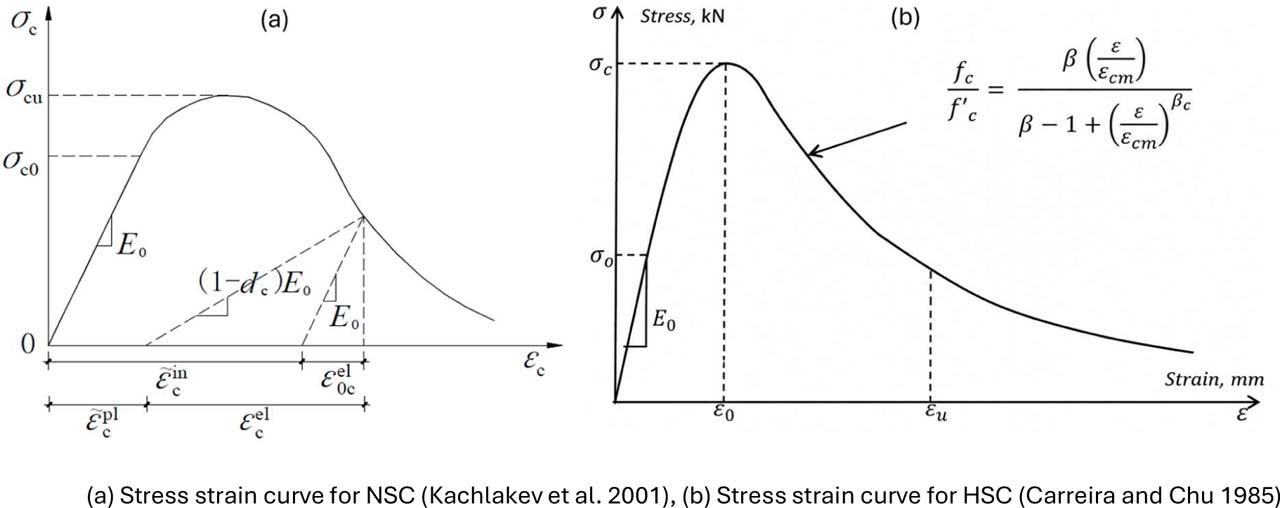
Figure 2:
Plastic damage curve of ordinary concrete under uniaxial compression
The von Mises yield criterion is established by comparing the von Mises stress and yield strength, and if a material’s stress exceeds its ultimate tensile strength, it said to have yielded. The stress state in steel is usually a multiaxial state; hence the von Mises yield criterion can be applied to provide an indication of whether yielding of the steel has occurred. A bilinear isotropic model, according to the von Mises yield criteria of steel which is a most common model for steel behaviour in nonlinear numerical modelling system, was employed to represent reinforcing steel and steel plate. Structural steel modelling usually adopts a Poisson coefficient of μ = 0.3, which was also applied here. Steel bearing plates are considered as elastic and linear in the analysis because these plates mainly transfer load to a foundation but do not reach yield strength for this range of load. The actual state of these plates was then included in the numerical model in ANSYS software. In This study, a modulus of elasticity of (E = 200 GPa) was used for both the reinforcing steel and steel sections in all models used (Tjitradi et al. 2017).
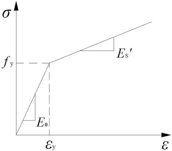
Figure 3:
Stress–strain curve of steel [24]
The constitutive model for normal concrete in ANSYS is also based on damage plasticity that describes gradual degradation in strength and stiffness due to crushing and cracking. SOLID65 is one of the concrete’s most common elements used in ANSYS: it’s an 8-noded, 3 degrees of freedom element with tetrahedron shape. This component describes the behaviour of concrete subjected to various loading conditions (Handhal et al. 2023) this has been used as it is able to take into account plastic deformation, yield and crushing. Concrete behaviour in ANSYS is defined using the properties of materials including ultimate uniaxial compressive and tensile strengths, modulus of rupture, Poisson’s ratio, and reduction factor of stiffness. The LINK180 element is a three-dimensional element that has two nodes with three degrees of freedom each node to model the steel reinforcement. This element has a bilinear stress-strain curve with elastic perfectly plastic material behaviour which means the yield value governs the yielding and failure of the material. The thing was too updated for the various steel section in the beam to be concrete modelled with a shell element (SHELL41) since represented S-shape insert. SOLID185 – An 8-node, three degree-of-freedom elements in the finite element model of steel plates located at the loading area. To avoid the stress concentration and local failure in concrete element at external loading point, SOLID185 is defined to that region of applying load. A linear stresses strain curve with a modulus of elasticity of 210 GPa (Handhal et al. 2023). In ANSYS, the regular concrete constitutive model uses damage plasticity to represent the gradual degradation of concrete over time due to crushing and cracking.
3.2. Modelling and Analysis Assumptions
In this modelling case, the von Mises equivalent stress was the basis for selecting the main post-processing criterion to evaluate stress state in steel items of numerically modelled encasing steel section and reinforcing bars where bilinear material model corresponding to ductile isotropic yielding behaviour has been utilized. This method is specifically significant at the out-of-plane segments, where the variation in beam path produces nonlinear multiaxial stress states which a single stress component cannot describe, to detect zones subjected to local yielding and aid reinforcing design (Ghaedi et al. In the concrete domain von Mises contours were only used to qualitatively indicate how stresses flowed and when this load-path redirection occurred at the connection zones; the actual failure of concrete was forced through direct coupling with a concrete plasticity failure (CPF) model implemented through the SOLID65 element in ANSYS which incorporated a Willam-Warnke-type failure surface in compression (William and Warnke 1975), far better representing the brittle pressure-sensitive behaviour of concrete then did a pressure-independent von Mises assumption. In addition, perfect bond between the steel section and surrounding concrete was assumed based on limited slip behaviour in similar composite RC configurations found in literature, and because of adequate embedment length and mechanical interlock in the tested specimens while the applied static loading represented a point load compatible with that used for validation (Mohsin et al. 2021) and (Albegmprli et al. 2025). The assumptions made are relatively rational as the research emphasizes on global structural response, strength, stiffness and failure mode rather than localized bond-slip behaviour.
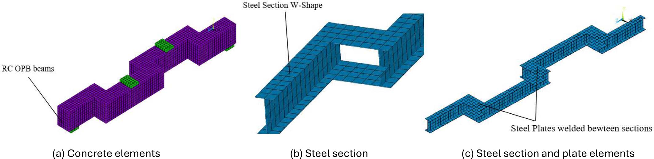
Figure 2:
The finite element model shows the mesh of OPB beams in ANSYS
3.3. Mesh Sensitivity Analysis
Before the main parametric study, a mesh sensitivity analysis was performed to evaluate the precision and computational efficiency of the finite element model. Different mesh densities were studied by gradually refining the SOLID65 element size of concrete elements in addition to that, steel section shell elements and LINK180 reinforcement elements; physical beam dimension and boundary conditions remained unchanged. To assess convergence, the ultimate load, midspan deflection, and cracking load for each mesh configuration were monitored. The coarse meshes showed appreciable numerical instability and tend to overestimate stiffness slightly, whereas too many fine meshes resulted in a tremendous increase of computational time without improvement of accuracy. The results indicated that when the total number of elements exceeded approximately 13,142, and any further refinements produced insignificant changes (less than 2%) in the predicted values for ultimate load and deflection. The mesh was focused in particular in the connection zones between segments, where most of the stress concentration and combined shear-torsional effects occurred; a meshed OPB beam model is illustrated in (Figure 3). From this analysis, the identified mesh density was used for all further models, as it represented an adequate compromise between solution accuracy and computational expense. This guaranteed that the results presented represent the actual localized stress at the direction-changing segments with no artifacts from mesh or other dependency.
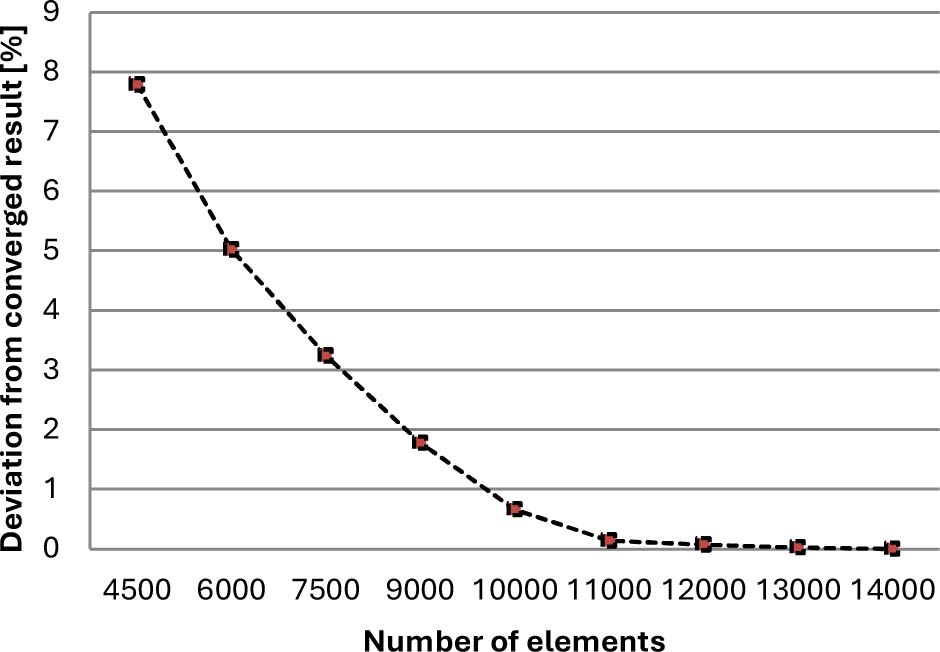
Figure 3:
FE model mesh analysis curve
3.4. Loading, and Boundary Conditions
The Figure 4 illustrates the loading conditions and supports for the simulated model. To ensure the real simulation of model that have matching with the same condition of the experimental beam, the ends were fixed entirely. In addition to restrained rotation, the vertical and horizontal displacement of the models were also restrained to reflect realistic conditions which allowed for shear, flexural, and torsion stresses to develop. The load applied on the steel plates; this value divided into number of nodes to distribute over area and decreasing stress concentration at node attaching to loading zones. Placing the load or support directly at a small point can lead to numerical problems within the program, such as infinite stress values or instability in the numerical solution. Therefore, the inclusion of a steel plate helps distribute forces across multiple nodes within the numerical mesh and allows the program to calculate stresses and strains more stably and realistically.
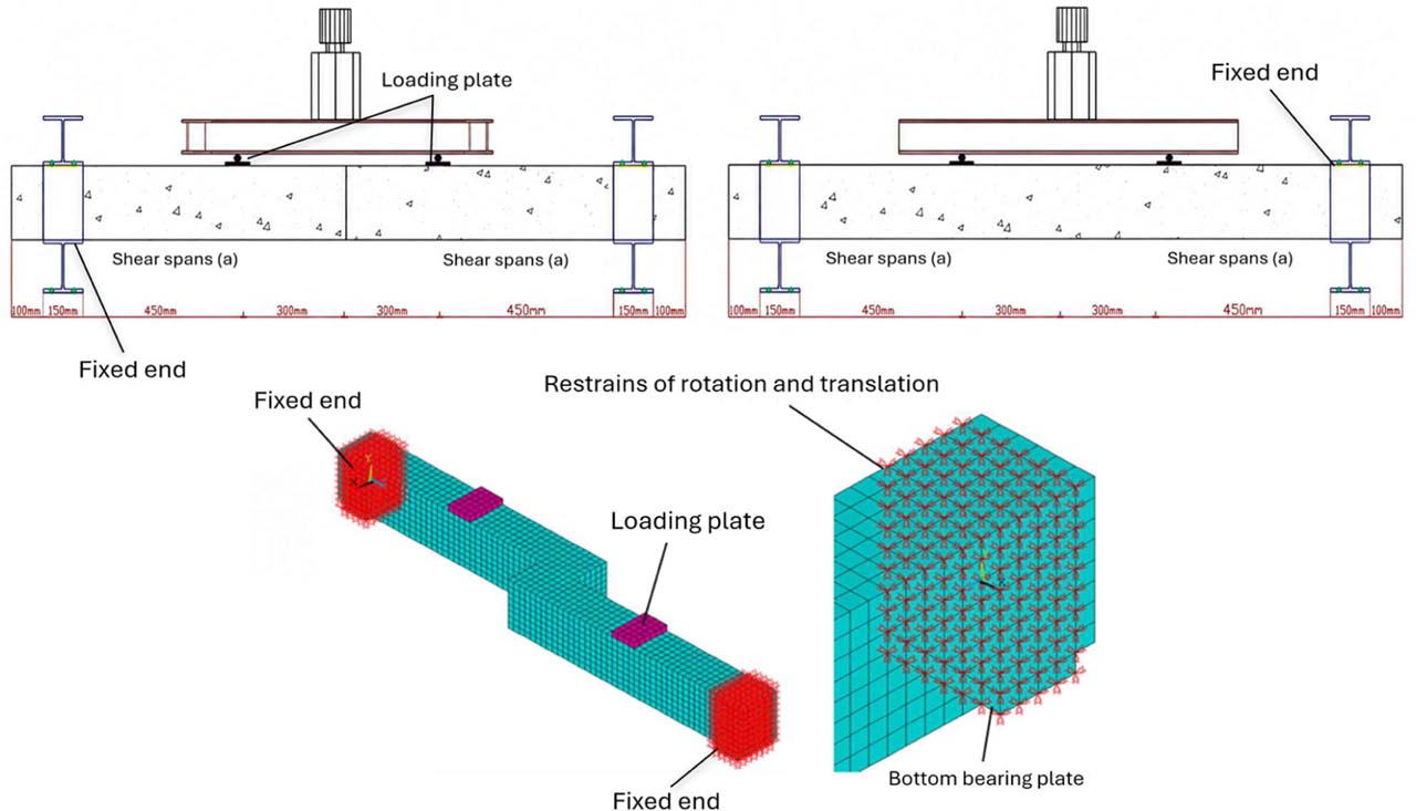
Figure 4:
Boundary condition of OPB beams details
This representation more accurately reflects realistic limit conditions found in the laboratory or on-site, where steel plates are actually used for loading to avoid localized cracking in concrete under direct load. This analysis examines the effect of flexural stress incorporation with the combined shear and torsional stresses of OPB beams when subjected to a two-point load in order to evaluate their structural performance. In ANSYS, a steel plate is typically represented using solid elements such as SOLID185 and is bonded to the concrete through a perfect bond without using contact elements such as CONTA174 and TARGE170 in order to distribute the whole forces over the entire beam. This feature is essential to obtain highly accurate results in this type of beam. Therefore, the use of the plate with perfect bond is not a secondary detail, but rather an essential part of accurate modelling for any numerical analysis of a loaded or supported concrete beam as illustrated in Figure 4.
3.5. Solution Controls in ANSYS
A full Newton-Raphson iterative method was chosen because it captures the progressive nonlinear response of concrete cracking, crushing, and stiffness degradation with increasing load (Automatic time stepping was then employed to divide the applied load into multiple substep for each increment so that the solver could flexibly adjust the substep size depending on convergence behaviour setting a smaller substep size when convergence became challenging near cracking and ultimate load stages, while increasing it during the early, near-linear response phase to improve computational efficiency. At each substep, convergence was evaluated with respect to force and displacement criteria, using the default tolerance values from ANSYS APDL, or as indicated otherwise. As also described, the shear transfer coefficients (both for open and closed cracks) were not allowed to decrease below 0.2 to avoid numerical instability due to low beam values which did not converge as shown previously. At the load step where numerical divergence occurred, the analysis was terminated as this step corresponded to solution divergence and was considered a representation of the ultimate load (or collapse point) from a physical standpoint. The line search options were enabled to improve convergence stability in the nonlinear post-cracking region, especially for OPB configurations (in which combined shear-torsional-flexural interaction increased the complexity of the solution path).
4. Verification of Finite Element Modelling
To validate this numerical model created by ANSYS, a comparison was made between the results of numerical simulation and documented experimental results on reinforced concrete beams tested previously in the laboratory under similar conditions (Mohsin et al. 2021) and (Albegmprli et al. 2025). The experimental reference model is not arbitrary but justified because there is a very close match in terms of most, including geometry and structural properties (dimensions, reinforcement ratio, type of reinforcement, load form and support type) between the experimentally tested beams (Mohsin et al. 2021) and the numerical models implemented in this work. A nonlinear material model was adopted for concrete considering tension, compression and gradual collapse. The material properties were entered as that of the graphed reference experimental study (compressive strength, Young’s modulus and Poisson’s ratio). A concentrated load at the centre of the simply supported beam was simulated to be loaded in the same way as it did in place during the experiment. In order to make this model realistic, the boundary conditions were designed appropriately. The full nonlinear analysis was performed using ANSYS, and the results for maximum load and maximum deflection were displayed as the cracks were developed. The results showed acceptable agreement with the experimental values, as the difference in the maximum load was about 1.96–5.29% and in the deflection about 6.87–8.33%. These percentages are acceptable within the engineering tolerable limits evidencing good agreement with the model and an efficient representation of a real-reinforced concrete bending response. The correlation was also good for the failure mode, the point of initiating cracks and their propagation where they started from lower tension fibres at mid-seam propagating upwards before appearing as oblique cracks to supports, as per experimental study. This indicates the ability of the numerical model to represent the post-cracking behaviour and ultimate capacity of the element. The slight difference between the numerical model and the laboratory results is attributed to a number of factors, such as the approximation in representing the micromechanical properties of concrete, the effects of sliding between steel and concrete, and differences in laboratory equipment, such as the accuracy of measuring instruments and environmental changes. However, all these differences remain within limits that can be neglected for numerical analysis. Therefore, it can be concluded that the model’s numerical accuracy has been sufficiently verified and can be relied upon to represent and analyse other cases within the current research with high confidence, especially those cases that are difficult to test in the field or laboratory, such as the effect of changes in the shape of the reinforcement or in asymmetric loads or long-term loads. This verification also supports the basic hypothesis on which this research work is based and proves the validity of the model used as an effective and reliable analytical tool. In a bending test, concrete often displays nonlinear behaviour up until it fails, at which time it collapses, usually because its tensile fibres have ruptured. Static stresses primarily affect two properties of concrete beams: their strength, which is the maximum load they can support, and their stiffness, which is the amount of deflection they undergo in response to a force. According to most experts in the field, the four-point bending test is the gold standard when it comes to evaluating beam behaviour. The dimensions, material properties, and test parameters of three specimens chosen from the existing literature data are detailed in Table 1 and 2.
Table 1:
Verification results include the failure load
| SP | Experimental load PE [kN] By (Mohsin et al. 2021) | Numerical load PN [kN] by (Albegmprli et al. 2025) | Numerical load PN (kN) | Matching (1) of PE and PN | Matching (2) of PE and PN |
|---|---|---|---|---|---|
| NSC-1OP | 369.2 | 364.77 | 376.42 | 101.96% | 103.19% |
| HSC-1OP | 385.99 | 363.99 | 394.54 | 102.22% | 108.39% |
| HSC-1OPT | 460.49 | 467.40 | 484.87 | 105.29% | 103.74% |
According to (Mohsin et al. 2021) and (Albegmprli et al. 2025), the specimens (NSC-1OP, HSC-1OP, and HSC-1OPT) used for validation were examined for their load-deflection curve, ultimate load, and maximum deflection, and the results are shown in Table 1 and 2 and Fig. 5. There is almost no difference between the predicted and actual behaviours of the load-deflection curves. Results of the verification in terms of the load deflection relationship are displayed in Table 1. There is a wide range of 98.8% to 101.5% for the experimental to numerical ultimate load ratio. The maximum deflection is also given in Table 1 with the numerical and experimental values.
Table 2:
Verification results include the maximum displacement
| SP | Experimental Disp. ∆E (mm) (Mohsin et al. 2021) | Numerical Disp. ∆N (mm) (Albegmprli et al. 2025) | Numerical Disp. ∆N (mm | Matching (2) of ∆E and ∆N | Matching (2) of ∆E and ∆N |
|---|---|---|---|---|---|
| NSC-1OP | 61.21 | 54.97 | 53.11 | 91.67% | 96.62% |
| HSC-1OP | 51.22 | 51.15 | 47.53 | 92.80% | 92.92% |
| HSC-1OPT | 49.62 | 48.63 | 46.21 | 93.13% | 95.02% |
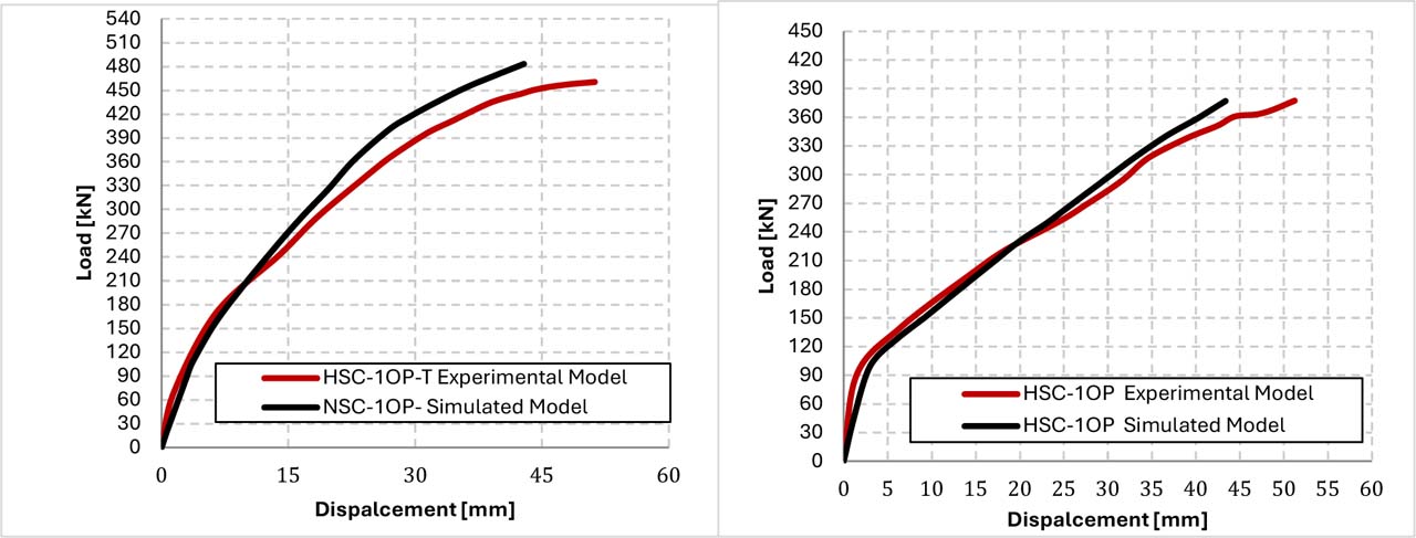
Figure 5:
Comparison between the experimental and simulated OPB beams
Although the experimental-to-theoretical deflection ratios are lower than the corresponding load values, they are nonetheless considered acceptable due to the delicate nature of concrete. Because the FEM is so basic and makes so many assumptions, it is not practical to conduct experiments to test how cracks spread. The variation between the experimental and theoretical test circumstances is explained by the characteristics of the concrete. In order to provide confidence in the parameters’ application, we compare the theoretical and real assessments of failure load, deflection, and fracture pattern. Because ANSYS cannot converge, the modelled beams cannot take any further loads, according to the final load analysis. This numerical model adopts a concrete damage model, which takes into account the changes that occur in the concrete material due to the development of cracks and the gradual weakening of its structure under loads, especially in the post-cracking phase until complete failure. After completing the numerical analysis, the results were compared with experimental data collected from real tests conducted on actual concrete beam models. It was observed that the numerical model predicted a maximum load value slightly higher than that observed in the experiment, exceeding it by approximately 8.5%.
5. Analytical Study
This research performed an analytical investigation of the behaviour of reinforced concrete beams containing out-of-plane structural components. The investigation evaluated the structural performance of these components to combined loads (bending moments, shear forces and torsional moments) on a total of thirteen specimen testing. Results of the investigated beams with cross-sectional dimensions of 150 × 200 mm and total length of 2000 mm These were strengthened with 6 T12 mm longitudinal bars (reinforced steel), and subsequently, additional transverse (T8 mm) reinforcements at spans of 81 mm along the beams to avoid failure due to shear and torsion, as imposed by the (ACI 318M-19 2019) guidelines as revealed in Fig. 6 and Table 3. The compressive strength of the concrete used was 40 and 70 MPa for the normal and high strength concrete, respectively, while the yield strength of the longitudinal bars was 420 MPa and that of the transverse bars was 560 MPa. To achieve the study’s objective, various beam models were designed, including a linear segment beam as a basic reference, as well as composite element models consisting of two, three, four, and five parts connected at angles different from the straight plane. This model aims to simulate the geometric deviations that real beams may encounter in structures. Instead of using a closed steel box as in previous studies (Albegmprli et al. 2025), it was replaced with S-shaped steel section placed in the middle of the beam as a reinforcement. The composite beams with a steel section were chosen due to their important structural advantages. It provides high efficiency in resisting moments about the neutral axis, allows for optimal interfacing with concrete, and improves the composite performance of the two materials. The structural shape of the S-section prevents the concentration of acute stresses at the contact points, effectively reducing out-of-plane deformations and increasing the beam stiffness at the centre, the region most susceptible to failure under combined loads. The steel sections are connected at the out-of-plane parts by using a steel plate with the same thickness as the steel flange of the S4 × 9.5. In addition to the models constructed from conventional concrete, similar numerical modelling will be conducted but using high-strength concrete with a compressive strength exceeding 70 MPa. The objective of this step is to evaluate the impact of concrete properties on the overall performance of beams. High-strength concrete is expected to reduce the development of torsional cracking, increase shear-bearing capacity, and improve the bonding behaviour between concrete and steel sections, enhancing the composite behaviour of the element and reducing the likelihood of slippage or separation between the two materials under dynamic or combined loads. This step also aims to accurately compare the mechanical performance of conventional and high-performance concrete models to determine the effectiveness of each system in improving the resistance of beams with complex geometric deviations. A two-point loading system was adopted to create a uniform bending moment in the centre and study the interaction between bending, shear, and torsion. To prevent stress concentration at the loading points and supports, 25 mm thick steel plates were placed to uniformly distribute the loads across the concrete surface and prevent sudden fracture of the model elements in the ANSYS environment, which was used for modelling and numerical analysis. In ANSYS, the total load is distributed across all nodes of the steel plates to ensure balanced distribution and provide an accurate representation of the structural performance of beams under the conditions studied. The objective of this study is to evaluate the combined performance of reinforced concrete beams subjected to geometric deflection and the effect of introducing S-section steel on their behaviour. It also aims to evaluate the role of high-strength concrete in enhancing this behaviour and achieving improved and stable structural performance under combined loading conditions.
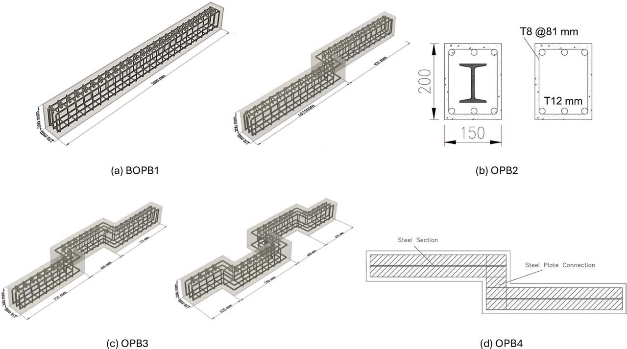
Figure 6:
Series one beams details
Table 3:
Details of specimens
| ID | Concrete Type | f′c (N/mm2) | Fr (N/mm2) | βt | βc | EC (N/mm2) | OPBs Number |
|---|---|---|---|---|---|---|---|
| BOPB1 | NSC | 40 | 3.92 | 0.213 | 0.718 | 29.73 × 10³ | Linear Section |
| NSC-OPB2 | NSC | 40 | 3.92 | 0.327 | 0.841 | 29.73 × 10³ | Two segments |
| NSC-OPB3 | NSC | 40 | 3.92 | 0.294 | 0.653 | 29.73 × 10³ | Three segments |
| NSC-OPB4 | NSC | 40 | 3.92 | 0.221 | 0.709 | 29.73 × 10³ | Four segments |
| NSC-OPB2C | NSC | 40 | 3.92 | 0.341 | 0.829 | 29.73 × 10³ | Two segments |
| NSC-OPB3C | NSC | 40 | 3.92 | 0.259 | 0.665 | 29.73 × 10³ | Three segments |
| NSC-OPB4C | NSC | 40 | 3.92 | 0.276 | 0.691 | 29.73 × 10³ | Four segments |
| HSC-OPB2 | HSC | 70 | 5.54 | 0.237 | 0.734 | 31.35 × 10³ | Two segments |
| HSC-OPB3 | HSC | 70 | 5.54 | 0.331 | 0.673 | 31.35 × 10³ | Three segments |
| HSC-OPB4 | HSC | 70 | 5.54 | 0.297 | 0.805 | 31.35 × 10³ | Four segments |
| HSC-OPB2C | HSC | 70 | 5.54 | 0.289 | 0.847 | 31.35 × 10³ | Two segments |
| HSC-OPB3C | HSC | 70 | 5.54 | 0.266 | 0.621 | 31.35 × 10³ | Three segments |
| HSC-OPB4C | HSC | 70 | 5.54 | 0.323 | 0.788 | 31.35 × 10³ | Four segments |
6. Results
Table 4 and 5 illustrates that the BOPB1 beam exhibits a greater ultimate load compared to the OPB beams based on the load-mid span deflection response. Moreover, when subjected to a load, the BOPB1 beam demonstrates reduced central deflection. This finding indicates that the BOPB1 beam surpasses the other beams in stiffness and ductility. The BOPB1 beam has a superior ultimate load compared to the others, signifying its capacity to withstand extreme loads prior to failure. Deflection readings were recorded at the midspan of each beam, which is where the maximum deflection occurs in a two-point loading configuration, that aligns with the location used for experimental verification against (Mohsin et al. 2021). Deflection readings at 250 mm intervals were also taken on beams containing out-of-plane segments, as well as at each connection point between the segments due to localized displacement variation across where the direction of the segment was changed. The stiffness of the BOPB1 beam is larger than other members, so it appears to be more rigid (see Fig. 6). This indicates that the BOPB1 beam is more resistant to deformation, as it experiences smaller deflections or displacements when subjected to similar levels of applied stress. Differences in the material properties such as compressive strength and other reinforcing specifications and differences in beam geometry and design very closely correlate to the observed differences in ultimate load along with deflection response of the beams. Such deviations can affect the ductility, stiffness, toughness, and load carrying capacity of the beams. The most important parameter introduced to improve the performance of this beam in terms of the out-of-plane component was encasing it with a steel box section. Steel parts bonded with the concrete increases the load-carrying and general strength of beam thus helps to increase toughness of concrete. The steel section provides additional shear, flexural and torsional resistance.
Table 4:
Results of NSC and HSCOPB
| Variable | ID | Yield load (kN) | Yield disp. (mm) | Failure load (kN) | δ corr. To Pu (mm) | εmax | Von Mises εmax | Von mises σmax (MPa) |
|---|---|---|---|---|---|---|---|---|
| Series One ref. | BOPB1 | 184.52 | 8.92 | 604.66 | 30.12 | 0.00373 | 0.019236 | 405.19 |
| NSC | NSC-OPB2 | 138.97 | 10.17 | 379.41 | 42.46 | 0.01981 | 0.057806 | 401.19 |
| NSC-OPB3 | 127.56 | 8.56 | 289.37 | 33.36 | 0.02252 | 0.067392 | 401.65 | |
| NSC-OPB4 | 126.18 | 8.44 | 229.14 | 21.44 | 0.02199 | 0.017716 | 180.66 | |
| Composite NSC | NSC-OPB2C | 154.95 | 13.80 | 638.93 | 38.77 | 0.0149 | 0.04512 | 426.51 |
| NSC-OPB3C | 152.43 | 8.88 | 441.00 | 28.46 | 0.01637 | 0.048753 | 412.24 | |
| NSC-OPB4C | 128.07 | 9.45 | 304.30 | 15.84 | 0.01598 | 0.039801 | 384.02 | |
| Series Two ref. | HSC-BOPB1 | 188.00 | 9.20 | 712.89 | 27.84 | 0.00351 | 0.018304 | 412.68 |
| HSC | HSC-OPB2 | 200.67 | 11.15 | 586.57 | 38.78 | 0.01894 | 0.055671 | 397.85 |
| HSC-OPB3 | 168.77 | 7.43 | 430.29 | 22.36 | 0.02131 | 0.064788 | 403.13 | |
| HSC-OPB4 | 142.94 | 8.16 | 353.79 | 21.44 | 0.02011 | 0.015602 | 176.54 | |
| Composite HSC with section | HSC-OPB2C | 225.36 | 11.90 | 730.86 | 36.98 | 0.01387 | 0.041782 | 434.76 |
| HSC-OPB3C | 193.07 | 10.59 | 542.60 | 28.63 | 0.01555 | 0.045501 | 418.23 | |
| HSC-OPB4C | 155.52 | 7.03 | 418.18 | 17.61 | 0.01512 | 0.03634 | 389.56 |
Table 4:
Results percentages of NSC and HSCOPB
| ID | Yield load changing percentage | Yield disp. changing percentage | Failure load: changing percentage | δ changing percentage | εmax changing percentage | Von mises εmax changing percentage | Von mises σmax changing percentage |
|---|---|---|---|---|---|---|---|
| BOPB1 | - | - | - | - | - | - | - |
| NSC-OPB2 | −24.69% | 14.01% | −37.25% | 43.79% | 431.13% | 200.51% | −0.99% |
| NSC-OPB3 | −30.87% | −4.04% | −52.14% | 12.97% | 503.97% | 250.34% | −0.87% |
| NSC-OPB4 | −31.62% | −5.38% | −62.10% | −27.40% | 489.62% | −7.90% | −55.41% |
| NSC-OPB2C | −16.02% | 54.71% | 5.67% | 31.28% | 299.65% | 134.56% | 5.26% |
| NSC-OPB3C | −17.39% | −0.45% | −27.07% | −3.62% | 339.10% | 153.45% | 1.74% |
| NSC-OPB4C | −30.59% | 5.94% | −49.67% | −46.36% | 328.53% | 106.91% | −5.23% |
| HSC-BOPB1 | − | − | − | − | − | − | − |
| HSC-OPB2 | 6.74% | 21.20% | −17.72% | 39.30% | 439.29% | 204.15% | −3.59% |
| HSC-OPB3 | −10.23% | −19.24% | −39.64% | −19.68% | 506.72% | 253.96% | −2.32% |
| HSC-OPB4 | −23.97% | −11.30% | −50.37% | −22.99% | 472.69% | −14.76% | −57.22% |
| HSC-OPB2C | 19.87% | 29.35% | 2.52% | 32.83% | 294.99% | 128.27% | 5.35% |
| HSC-OPB3C | 2.70% | 15.11% | −23.89% | 2.84% | 342.65% | 148.59% | 1.34% |
| HSC-OPB4C | −17.27% | −23.59% | −41.34% | −36.75% | 330.64% | 98.54% | −5.60% |
The out-of-plane component changes the beam geometry and loading path so that it is subjected to a package of bending and torsion loads. This combined loading condition causes impairment of the maintaining capacity and also the ductility of these beams. The observed reduction in ductility and load-bearing capacity highlights the importance of incorporating out-of-plane effects into beam design. Incorporating methods such as utilizing greater strength steel for enhanced torsional reinforcement can improve the behaviour and performance of beams with out-of-plane components, facilitating superior load resistance and increased ductility. Table 4 and 5 demonstrates that the structural performance of the tested reinforced concrete beams with the out-of-plane component, in contrast to ordinary reinforced concrete beams under bending, displays reduced ductility. The combined loading condition leads to a reduction in the load-bearing capacity and ductility of the beams. OPB without a steel section had lower deflection along the span due to the development of torsion along the middle connected out-of-plane components, as demonstrated by an average displacement that was recorded at each of 32.42 mm and 27.69 for the OPB beams made with NSC with and without a steel section, respectively. The deflection decreased as a result of the increase in the number of concrete sections that were out of plane, which resulted in less deflection for the OPB4-OPB4 and NSC-OPB4C.
6.1. Series One
6.1.1. NSC Non-composite Beams
The results of the analytical tests shown in the tables above indicate a significant effect of longitudinal joints in concrete beams on structural performance at both the yield and failure stages. Model BOPB1 was chosen as the reference model because it represents a homogeneous concrete beam free of joints, while models NSC-OPB2, NSC-OPB3, and NSC-OPB4 represent beams containing one, two, and three joints, respectively—that is, they are composed of two, three, and four connected parts. The purpose of the comparison is to study the effect of increasing the number of joints on the strength of the beam, both at the yield stage and at failure. Looking at the yield load results, the reference model BOPB1 recorded the highest value of 184.52 kN. The model NSC-OPB2 registered a yield load of 138.97 kN, being decreased by approximately 24.69%. The drop is because this joint in the mid span of the beam reduces section resistance to initial stress under the first load. The performance integration achieved by monolithic concrete cannot be realized when the connection between two separate concrete sections does not provide sufficient ability to reliably transfer moments and shear. For the case using three sections connected (NSC-OPB3 model), we got a yield load of 127.56 kN, which corresponds to a reduction of 30.87% over the reference model. This further reduction accounts for the combined effect of more than one joint, as they create new potential stress concentration areas and a higher chance of an initial crack at the simultaneous connections. The attachments also interrupt the continuity of the reinforced concrete; hence, each additional joint reduces the stiffness and load-resistance capacity of the whole-system. The yield load in the NSC-OPB4 model containing four sections with three joints was only 126.18 kN, 31.62% lower than that in the full BOPB1 model. This reduction corroborates that joints, regardless of the careful execution with which they are implemented, remain as critical components in a structural system and their early effect on the force-displacement relationship of the section. It is therefore sound that as the number of joints increases, so does the number of weak points and, since joint systems have to cope with same box per segment reduces system integrity in its entirety thus microslips are more likely present which explains uneven distribution of loads and stresses. And for Failure Load, which indicates maximum load that a beam can sustain before failing bean, the model given by BOPB1 as reference with 604.66 kN show a highest capacity. In contrast, the NSC-OPB2 model recorded a maximum load of 379.41 kN, representing a sharp 37.25% decrease. This decrease reflects that the first longitudinal joint reduced the system’s ability to withstand ultimate loads, due to poor shear force transfer between the two parts, in addition to poor structural integrity and cohesion. In the NSC-OPB3 model, the ultimate load decreased to 289.37 kN, a decrease of 52.14%. This significant decrease is clear evidence that multiple joints directly affect the ultimate structural performance of the element. A beam with three continuous sections contains two zones of force transfer, increasing the likelihood of collapse at those points under high loads due to joint opening or stress concentration. The NSC-OPB4 model recorded the lowest ultimate load value at 229.14 kN, a decrease of 62.10% compared to the reference model, as illustrated in Figure 7. The results confirmed that increasing the number of direction-changing segments along the concrete beam progressively degraded its structural performance. As the number of segments increased, torsional-shear stresses accumulated at the connection zones, leading to a gradual reduction in ultimate load, ductility, and energy absorption. This behaviour is consistent with (Albegmprli et al. 2025), who found that increasing the number of connected segments in beams with out-of-plane parts increased the torsional-shear stresses along the beam and reduced the ultimate load-carrying capacity, confirming that each additional change in segment direction introduces a new discontinuity that weakens force transfer and accelerates failure at the joints.
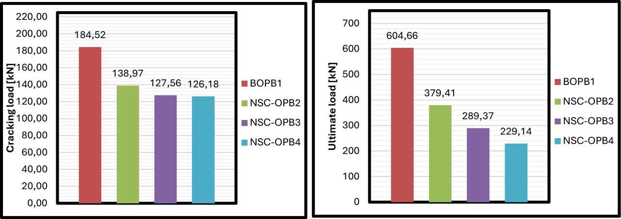
Figure 7:
Cracking and ultimate loads of NSC Non-Composite OPB beams
This reflects that increasing the number of joints to three, dividing the beam into four sections, led to a sharp decrease in the ultimate strength the beam can withstand. This decline can be scientifically explained by the fact that the large number of joints increases the complexity of force distribution within the section and weakens the structural mechanism upon which the section relies to resist loads after cracking, especially in the post-plastic limit stage of concrete. Overall, these results indicate that the structural performance of concrete beams is negatively affected by the presence of joints, and that this effect increases significantly with the increasing number of joints. Joints act as weak points within the section, affecting the distribution of moments, shear forces, and strains. Furthermore, the integration between the sections becomes less efficient compared to homogeneous beams, affecting performance in both the elastic phase (before yielding) and the inelastic phase (after cracking initiation and until failure). Therefore, the structural design of multi-segment beams requires taking these effects into account and ensuring effective means of transferring forces across the joints, such as the use of mechanical joints or advanced adhesives, to improve joint performance and reduce their negative impact. If these joints cannot be avoided, they must be reinforced using additional techniques such as fiber wrapping, metal strips, or special joint treatment to ensure the best possible force transmission and prevent stress concentrations that could lead to premature failure.
6.1.2. NSC Composite Beams
When analysing the behaviour of the structural models NSC-OPB2C, NSC-OPB3C, and NSC-OPB4C, which represent two-, three-, and four-part concrete beams, respectively, embedded with S-shaped steel sections and connected using steel plates, a clear effect of this steel reinforcement on the structural performance of the models can be observed, particularly when compared to their concrete counterparts, NSC-OPB2, NSC-OPB3, and NSC-OPB4, which do not contain internal steel sections. The results demonstrate an improvement in yield and failure strength as a result of this reinforcement, supporting the effectiveness of using internal steel sections to improve the mechanical performance of composite beams. In term of yield load, the NSC-OPB2C model had capacity to carry a yield load of 154.95 kN while it was only 138.97 kN for the group having no steel section (NSC-OPB2). An S-shaped reinforcement will increase the beam bearing yield load by 16.02% in this case.
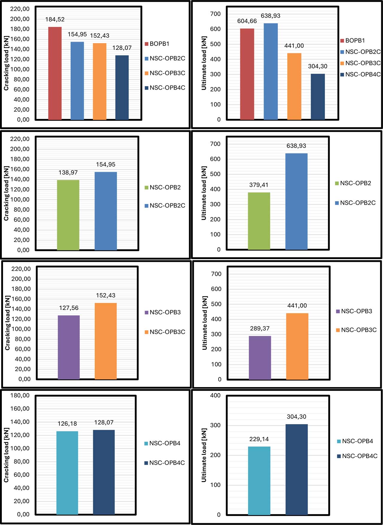
Figure 8:
Cracking and ultimate loads of NSC Composite OPB beams
This improvement is directly correlated with the embedded steel section in concrete, which provided a complementary flexural reinforcement and stress distributions. one of the properties that characterizes this type of connection is the presence of bonding plates between both steel sections, which reduces relative sliding in the section, improving joint behaviour and therefore giving rise to an increase in stiffness of composite section. The yield load for the NSC-OPB3C model with three bonded sections of concrete was 152.43 kN, which is 19.50% higher than that of the corresponding unreinforced model (127.56 kN). That a relatively higher increase was observed indicates that as the number of concrete joints is approached, steel sections play a more leading role because they act to resist bending and also help to achieve good connections between the three sections through tie plates, relieving stress concentration at the joints before initial cracks occur.
The NSC-OPB4C (the most complex scenario considering the number of connected sections, n = (4) achieved a yield load (128.07 kN) larger than that of any unreinforced NSC-OPB4s, also significantly higher at 126.18 kN (+1.50%). the ratio achieved was not as high as in the previous models. The reason for this can be attributed to the fact that tripling of its joints, disables a section to experience fully the full impact of steel sections. This makes transfer of force more complex and leads to joints becoming weak points that are unpredictable even when incorporating the steel within. the steel plates in this model could very well be completely lacking, preventing good bonding between the steel elements and compromising the contribution of that steel to performance. In terms of ultimate load or failure load, the NSC-OPB2C model recorded a maximum load of 638.93 kN, compared to 379.41 kN in the unreinforced model, a significant increase of 68.35%. This significant improvement clearly demonstrates the critical role of the steel section in enhancing the section’s load-bearing capacity under high loads. The steel contributes to resisting flexural stresses after the cracking stage and maintains the section’s ability to continue to withstand loads even after concrete failure in certain areas, giving the system a high ductile behaviour. For the NSC-OPB3C model, the maximum load value reached 441.00 kN, compared to 289.37 kN in the NSC-OPB3, representing a 52.41% improvement. The incorporation of a steel section within the concrete beam resulted in significant structural performance improvements that contributed to offsetting much of the strength and ductility loss due to beam segmentation. The steel section was a structural bonding part that linked the gaps at the connection precluding abrupt stress transfer zones and postponing brittle failure. This result supports (Albegmprli et al., 2025), who reported the covering the out-of-plane parts of beam sections in steel poles improved their performance behaviour, overcoming losses completed by discontinuities within the concrete segments and led to an increase in ultimate load carrying capacity. They also indicated that the ductility did indeed increase, and for their particular results, the steel section improved both ductility and energy absorption with a 63−67% increase in ductility index comparing beams with and without steel section. This reinforces steel encasement as not simply a strengthening but, in some cases, a structural provision needed to restore the load-transfer continuity lost in segments which change direction for beams experiencing torsion, or combined shear and torsion and flexural stresses. This reflects that the steel section compensated for the weak connection resulting from the presence of two joints in the beam and helped distribute forces more evenly between the three parts, especially in the contact areas. In the more complex NSC-OPB4C model, the maximum load improved from 229.14 kN to 304.30 kN, an increase of 32.83%, as shown in Figure 8. Although this increase is positive, it remains less than the improvement recorded in the models with fewer joints. This relative decline can be explained by the fact that, while the steel section contributes to improved performance, its effectiveness decreases with an increasing number of concrete joints, due to the increased impact of partial slips and unbalanced force distribution. From a structural perspective, reinforcing multi-joint concrete beams with S-shaped internal steel sections is an effective strategy for improving section performance at both the yield and failure stages. Although the improvement varies from model to model depending on the number of joints and the nature of the connections between the sections, the general trend indicates that this type of reinforcement significantly improves performance and reduces the negative effects of concrete discontinuity. Tie plates between steel sections have also been shown to play an important role in ensuring section integrity, but additional optimization may be required for models containing more than two joints to maximize the use of the steel section. Therefore, the design of composite beams requires a careful balance between the number of joints, connection methods, and steel section distribution to ensure the best possible structural performance.
6.2. Series Two
6.2.1. HSC Non-composite Beams
The HSC-OPB2, HSC-OPB3, and HSC-OPB4 models are two-, three-, and four-part concrete beams, respectively, constructed from high-strength concrete with a compressive strength of 70 MPa. They differ from their counterparts, NSC-OPB2, NSC-OPB3, and NSC-OPB4, only in the concrete type, as the latter models are constructed from lower-strength normal-strength concrete. Comparing the performance of these high-strength concrete models with the full reference model, HSC-BOPB1, which represents a homogeneous high-strength concrete beam without any joints, clearly demonstrates the effect of concrete type on both yield and failure behaviour, especially when the results are compared with those of conventional models constructed from normal concrete. Regarding yield load, the HSC-BOPB1 reference model recorded a value of 208.88 kN, higher than all segmented models made of high-strength or ordinary concrete. The HSC-OPB2 model, which consists of two connected sections, recorded a yield load of 156.75 kN, representing a 24.96% decrease compared to the reference model. Comparing this with the NSC-OPB2 model made of ordinary concrete, which recorded a 24.69% decrease compared to the NSC-BOPB1 reference model, we note that the effect at the yielding stage is very similar in both cases, indicating that the concrete type does not significantly alter the behaviour in the initial (yielding) stage, as much as the construction joints play a crucial role in reducing the initial stiffness of the section. In the three-part HSC-OPB3 model, the yield load was 153.62 kN, a 26.44% decrease compared to the reference model HSC-BOPB1. The NSC-OPB3 saw a 30.87% decrease compared to the reference model. This indicates that the use of high-strength concrete in a model with three joints slightly improved the yielding performance. That is, the high-strength concrete mitigated the effect of multiple joints but did not completely address them. In the four-part HSC-OPB4 model, the yield load was 148.28 kN, a 29.04% decrease compared to the reference model HSC-BOPB1. In contrast, the NSC-OPB4, made of ordinary concrete, saw a 31.62% decrease. This means that the high-strength concrete slightly improved the performance of the four-part model in the yielding phase (approximately 2.5% relative improvement) compared to its counterpart made from ordinary concrete. When moving to the failure load phase, which represents the ultimate load capacity of the beam, the results show that the high-strength concrete had a greater impact compared to the yielding phase. The reference model HSC-BOPB1 recorded a maximum load of 663.95 kN. In the HSC-OPB2 model, the value decreased to 513.78 kN, a decrease of 22.63%, significantly lower than the 37.25% decrease recorded in the NSC-OPB2 model. This significant difference indicates that the high-strength concrete significantly improved the ability of the segmented beam to resist ultimate loads, reflecting its increased resistance to shear, compression, and cracking after the yielding phase. In the HSC-OPB3 model, the maximum load was 443.85 kN, a 33.17% decrease compared to the reference model. In the NSC-OPB3, the decrease was 52.14%, indicating that the use of high-strength concrete in the three-part model significantly reduced the loss in ultimate strength by more than 19%, as shown in Figure 9.
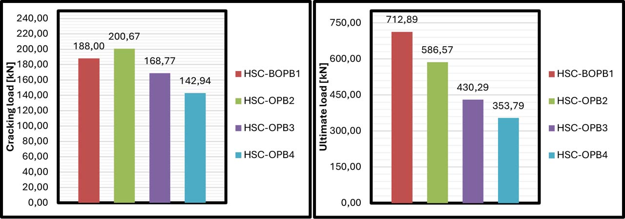
Figure 9:
Cracking and ultimate loads of HSC non-composite OPB beams
Higher levels of initial stiffness, as indicated by steeper load-displacement curves for the early stage of the loading process were also observed when increasing concrete compressive strength from NSC to HSC. Such trend was evident and is in accordance with that observed by Mohsin et al. where the cracking load of all NSC beams performed alone were noted to be the highest among tested specimens (and that for the beam containing one out-of-plane part made of NSC was considerably lower than that recorded for straight NSC beam), whilst HSC beams containing an out-of-plane part could have obtained equal values as far as longitudinal splitting cracking load is concerned. This indicates that an increase in compressive strength partially recovers the decrease in cracking-load associated with beam segmentation, but not entirely enough to replicate the performance of a straight configuration. Although compressive strength was beneficial, higher levels of fibre were required to provide better post-cracking behaviour, and as such some methods like test 3 which resulted in unsatisfactory performance despite more complete compression resistance. The load-carrying capacity of the HSC specimens without internal steel reinforcement decreased remarkably shortly after formation of the first cracks due to the brittle character of high-strength concrete. This observation is consistent with (Mohsin et al. 2016 2021) done improvement of HSC beam with out-of-plane part by enhancing torsional reinforcement at about 19.75% ultimate load among the same beam without torsional reinforcement, it can be concluded that strength of concrete alone is not sufficient for sustaining post-cracking performance and avoiding sudden brittle failure in such beams, additional shear reinforcement is critical. This is further evidence that high-strength concrete reduces the effect of joints and enhances performance at maximum loads. The HSC-OPB4 model recorded a maximum load of 358.41 kN, a 46.02% decrease compared to the reference model. The NSC-OPB4 showed a 62.10% decrease, reflecting a 16.08% improvement due to the use of high-strength concrete. Although this model still shows a decrease in ultimate strength compared to the full model, high-strength concrete clearly reduced this decrease, and its benefits appear to increase with the increase in the number of joints in the section, as it helps strengthen weak points at the joints and improves tensile and shear resistance after cracking. Overall, these results indicate that the use of high-strength concrete leads to a significant improvement in structural performance, particularly during the failure phase, where it exhibits greater load-bearing capacity even after the yield stage has passed, and reduces the impact of joints on the overall performance of the element. During the yield stage, however, the effect of high-strength concrete was relatively limited compared to the effect of joints, with the percentage decreases remaining close between the normal and high-strength concrete models. Therefore, high-strength concrete represents an effective solution for improving the performance of composite beams, especially in systems containing many joints.
6.2.2. HSC Composite Beams
The results of the HSC-OPB2C, HSC-OPB3C, and HSC-OPB4C models, which represent two-, three-, and four-part high-strength concrete beams with embedded S-shaped steel sections connected by steel tie plates, indicate a significant improvement in structural performance compared to their counterparts, HSC-OPB2, HSC-OPB3, and HSC-OPB4, which consist of the same number of sections but without any internal reinforcement with steel sections. The importance of this comparison lies in highlighting the effect of the embedded steel section on the section’s strength during both the yield and failure phases, in the context of using high-strength concrete with a compressive strength of 70 MPa. Regarding yield load, the HSC-OPB2C model recorded a value of 171.28 kN, while its counterpart, HSC-OPB2 without a steel section, recorded a lower value of 156.75 kN, indicating a 9.26% improvement. This increase reflects the steel section’s effectiveness in strengthening the section and improving its stress distribution during the yielding phase. It is well known that concrete, even with high strength, remains a relatively brittle material when cracks begin to develop. The presence of an internal steel section contributes to delaying the propagation of these cracks and improving the system’s stiffness. The bonding plates between the two steel sections also contribute to enhancing the integrity of the element and ensuring more uniform force transmission, reducing the effect of the joint in the middle of the beam. In the HSC-OPB3C model, which consists of three connected parts and includes an internal S-shaped section, the yield load was recorded at 165.61 kN, compared to 153.62 kN for the HSC-OPB3 model without steel reinforcement, representing a 7.80% increase. Although this increase is lower than that recorded in the two-part model, it remains a positive indicator of the effectiveness of the steel reinforcement, especially given the presence of two structural joints that increase the possibility of localized weakness at the connection points.
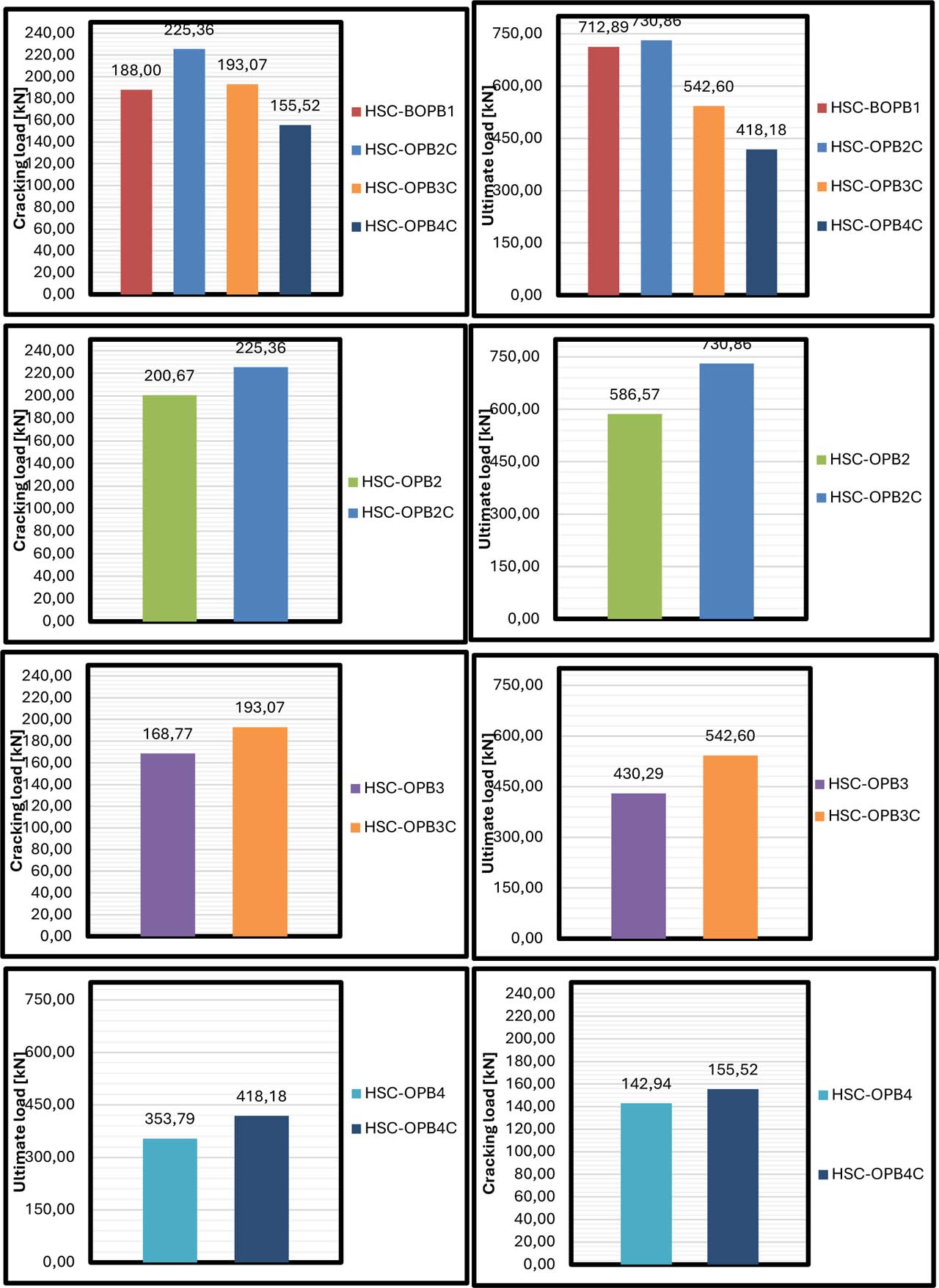
Figure 10:
Cracking and ultimate loads of HSC composite OPB beams
The steel section here serves a hybrid bonding role that offsets concrete discontinuities and contributes to increased effective property demand during the initial stages of loading. The yield load of the HSC-OPB4C model with a four-part and an internal S-shaped steel section was 160.52 kN, while that of the one without a steel section (the typical HSC-OPB4 model) was 148.28 kN, indicating an increase of 8.26%. That increase is due to the three joints in the section, but it shows that significantly, enough steel reinforcement was employed to make up for the weakness of greater number of joints and improve system initial-load capacity. This is when the performance of the steel tie plates between the sections (live load reaction) and the variability or consistency/quality of the beam elements may play a key role in this outcome. At the ultimate load (failure load), the influence of the steel sections is most prominent. The maximum value 649.15 kN was obtained at the HSC-OPB2C model, while a value of 513.78 kN is reached which was considerably high (26.32% advancement) by not having the steel section at the HSC-OPB2 model in comparison to each other. This difference indicates that the steel section contributes significantly to the behaviour of the beam after cracking, since during this time, especially in the post-yield phase, concrete ceases to be effective in resisting moments and steel begins to contribute more.
It was observed from the scale of variability on this results that LEB: at node C; OEB: at node D showed more ductile behaviour with more load carrying capacity against collapse, as we can see, in these cases steel is dominating (This case shows the effect of the Steel section which illustrates its importance). The maximum load was 563.87 kN in HSC-OPB3C model and it increased to 443.85 kN in unreinforced model, which is an increase of 27.03%. This figure reflects that the presence of the steel section significantly improved the three-part beam’s ability to continue to withstand high loads after cracks formed and the concrete lost some of its strength. The bonding plates between the steel sections also played a role in improving the overall stability of the section and reducing the possibility of localized collapse at the joints. The more complex HSC-OPB4C model recorded a maximum load of 480.43 kN, compared to 358.41 kN in the unreinforced model, an increase of 34.02%. Although the number of joints here was higher, the relative improvement in final performance was also higher, indicating that the effectiveness of the steel section is more pronounced the greater the system’s cracking weakness. It appears that the steel section not only served as an internal resisting element but also acted as a force-transmitting bridge between the four components, significantly compensating for poor concrete cohesion, contributing to delayed collapse, and increasing ultimate strength. Based on the above, it can be argued that the use of S-shaped steel sections within high-strength concrete beams is an effective option for enhancing structural performance, both at the yield and failure stages. This benefit increases as the number of joints in the section increases, demonstrating that internal steel could reduce the effect of concrete discontinuities and improve force transmission within the composite section. With tightly designed tie plates, the system becomes more integrated and exhibits more ductile behaviour, enhancing the overall structural safety of composite beams under high loads, as shown in Figure 10.
6.3. Load-displacement Relationship
The comparison of the relationship between the ultimate load and displacement of plain-concrete-type NSC-OPB2 and NSC-OPB2C models will reveal a fundamental difference in the flexural behaviour between these two types of models. like most non-linear models, the NSC-OPB2 model displays typical progression behaviour; where load increases with increasing displacement until reaching approximately 450 kN when the curve starts to flatten in a gradual manner indicating that the beam has entered an ultimate limit state post-cracking and approaching failure. This behaviour is a property of plain concrete which has minimal post-cracking resistance causing ductility loss and a less stable structural response after reaching peak load. In contrast, the NSC-OPB2C model, which has a section of steel embedded in the concrete beam behaved quite differently. The curve increased quicker and achieved a maximum load of around 650 kN, which is considerable improvement in the load capacity considering that for the unreinforced model this was much less. The progressive accumulation of torsional-shear stress concentrations at each joint due to the increasing number of connected segments exacerbated the differences in structural response between unreinforced and steel-encased NSC configurations. After preliminary flexural tests it was determined that each panel subsequently obtained an ultimate load of 380 kN (NSC-OPB3), characterized by stiffness degradation evidenced by curve flattening beyond a 30–35 mm displacement standard for unreinforced, multi-joint cross-section after crack propagation. The equivalent steel-reinforced configuration, NSC-OPB3C, reached an ultimate load over 500 kN when deformations surpassed 35 mm because joint-focused stresses redistributed via the embedded steel providing cross-sectional continuity through discontinuous segments. In the configuration comprising four segments, this disparity was augmented: NSC-OPB4 only reached 300 kN prior to failure at 22 mm (due to cumulative loss of structural continuity with every additional joint), while NSC-OPB4C withstood loads above 500 kN at 30 mm displacement. This is illustrated by the higher portion of strength recovery in higher segment counts (OPB4C as compared to OPB3C and OPB2C) that can be attributed to benefit of scaled structural contribution from the steel section due to greater extent of geometric discontinuity, which may be interpreted as a load-transfer mechanism compensating for increasingly lost monolithic action in the segmented concrete section. A similar but mechanistic trend, generated from the inherently brittle nature of high strength concrete stress-strain behaviour, was captured in the HSC series. The higher elastic modulus of HSC-OPB2 resulted in a larger initial stiffness and once the ultimate load of around 480 kN was reached, there was an abrupt post-peak strength loss that indicates limited plastic deformation capacity typical for unreinforced HSC. Also, HSC-OPB2C demonstrated a sustained post-cracking load resistance above 650 kN, which suggested that the embedded steel section offer secondary energy-dissipation mechanism able to compensate partially the low fracture toughness of HSC. Although the intrinsic material strength of HSC-OPB3 was higher than that of LSC-OPB, its post-cracking response was unsteady and it had lower capacity (≈ 400 kN where displacements did not exceed 30 mm), demonstrating that cross-sectional continuity once cracked dominates ductile capacity rather than compressive strength alone enabling uniform stress transfer across the segment joints.
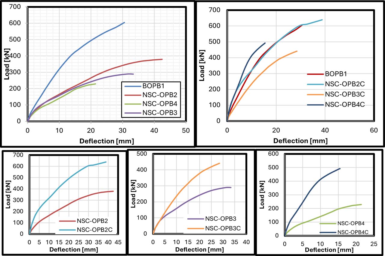
Figure 11:
Load-deflection relationship of NSC OPB beams
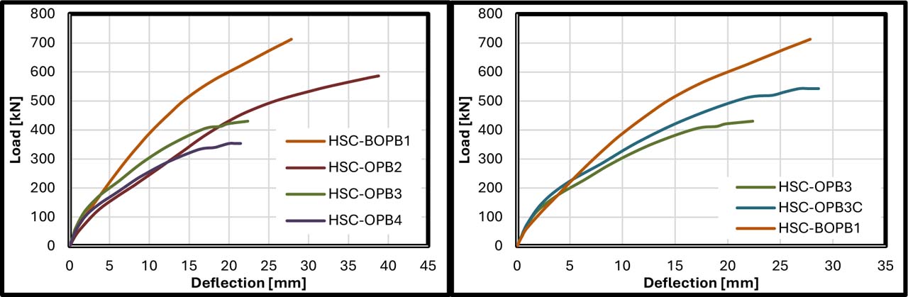
Figure 12:
Load-deflection relationship of HSC OPB beams
HSC-OPB3C further raised the ultimate load to around 540 kN at a response of over 35 mm, suggesting effective stiffness increase and critical crack propagation arresting across connection zones taking place in tandem. This contrast was most pronounced with the four-segment configuration, as HSC-OPB4 experienced brittle failure at about 300 kN and 20 mm due to insufficient joint-level force transfer while HSC-OPB4C reached nearly 520 kN with considerably higher displacement capacity.
6.4. Ductility Index
One definition of ductility is a material’s resistance to rupture under large deformations. According to (Park 1988), mild steel is a ductile material that can be bent and twisted without fracture; thus, the percentage of steel reinforcement in concrete is a good indicator of this. The ductility index is a metric for assessing ductility. The ductility index is defined as the ratio of the deflection at the yield point (Δy) to the deflection at the ultimate load (ΔU), as stated by (Park 1988). (Park 1988) used the same elasto-plastic yield point, whereas other authors offered alternative methods for estimating this term. Comparing the ductility index of the concrete specimens NSC-OPB2, NSC-OPB3, and NSC-OPB4 with the reference specimen BOPB1, which recorded a ductility value of 3.31, we find that the NSC-OPB2 specimen, which consists of two connected parts, achieved the highest ductility at 4.17, representing an increase of approximately 26% over the reference specimen. The ductility in the NSC-OPB3 specimen was increased to 3.90, and this value showed a moderate gain of about 18% over that for the reference specimen, suggesting good performance with an arrangement having three-connected segments when compared to all test specimens containing one or two joints. Nonetheless, the marginal improvements over NSC-OPB2 are less pronounced and this can likely be attributed to the larger number of parts requested leading to additional joints that may have an inherent weakness in transferring loads. The NSC-OPB4 model recorded a ductility lower than the reference model, at 2.54, a decrease of approximately 23%. This indicates that dividing the section into four parts reduces the integrity of the elements and increases the likelihood of separation or relative sliding between the parts, which reduces the ability to withstand deformation. The NSC-OPB2C composite model recorded a ductility of 4.63, the highest of all models, an increase of approximately 40% over the reference model. This indicates that the use of steel reinforcement within a section of only two parts provided more efficient stress transfer and additional flexural resistance, thus increasing the section’s ability to deform before failure. In contrast, the NSC-OPB3C model, which contains three parts and an internal steel section, achieved a ductility of 2.91, approximately 12% lower than the reference model. This reflects that the presence of the steel section was insufficient to compensate for the effect of the triangular configuration, which led to unbalanced load distribution and weak contact points between the concrete parts. The NSC-OPB4C model, which contains four parts and an internal steel section, achieved a ductility of 3.25, very close to the reference model and only slightly lower by about 2%. However, it was better than the unreinforced NSC-OPB4 model, which recorded a ductility of 2.54. This indicates that the steel reinforcement contributed to improved performance, but not as effectively as the NSC-OPB2C model. The differences between these results can be explained by the influence of the number of joints between concrete members and the effectiveness of the bonding between them. The higher the number of joints, the less deformability can be expected at weak points due to stress concentration; this means that embedded steel reinforcement is also correspondingly less effective if it is not used as a complete solution throughout all segments. Thus, the best results arise for a small cluster of closely linked members reinforced with internal links responsible for force transmission. For the ductility index of unreinforced versions, HSC-OPB2 achieved 4.28 as well as an increase by 31.3 for a two-segment configuration, whereas relative to the reference specimen HSC-BOPB1 (ductility index = 3.26), reduction of the indices for HSC-OPB4 and also HSC-OPB3 were obtained of − 7.7% & −24.8%, respectively regarding these three-segment and four-segment configurations This can be attributed to the effect of additional joints deteriorating deformation capacity when you take into account the inherently brittle behaviour of high-strength concrete. The steel-encased counterparts also displayed a comparable pattern: the ductility index ranged from 4.03 for HSC–OPB2C (23‰ above the reference) due to the contribution of both high-strength concrete stiffness and flexural stiffness provided by the embedded steel section. HSC-OPB3C registered 3.28, marginally more than the reference (0.6%), suggesting that the presence of significant steel reinforcement (30 percent of total longitudinal bottom chord area) was fully negated by through-the-depth conservativeness associated with a complex three-segment configuration. The average ratio of HSC-OPB4C was recorded to be 2.51–23% lower than the reference but slightly higher than its unreinforced counterpart (2.45) as revealed in Table 5, suggesting that steel reinforcement mitigated only a moderate fraction of the ductility loss associated with four-segment discontinuity.
Table 5:
Results of ductility indices, initial stiffness, and toughness
| Variable | ID | Ductility index | Ki [kN/mm] | Toughness [kN.mm] |
|---|---|---|---|---|
| Series one ref. | BOPB1 | 3.31 | 20.69 | 8929.60 |
| NSC | NSC-OPB2 | 4.17 | 13.65 | 8055.30 |
| NSC-OPB3 | 3.90 | 14.89 | 4814.40 | |
| NSC-OPB4 | 2.54 | 14.94 | 2457.80 | |
| Composite NSC | NSC-OPB2C | 4.63 | 11.22 | 11786.00 |
| NSC-OPB3C | 2.91 | 17.71 | 9004.20 | |
| NSC-OPB4C | 3.25 | 13.56 | 5856.70 | |
| Series Two Ref. | HSC-BOPB1 | 3.26 | 20.43 | 10693.40 |
| HSC | HSC-OPB2 | 4.28 | 20.07 | 9336.90 |
| HSC-OPB3 | 3.01 | 20.89 | 6906.60 | |
| HSC-OPB4 | 2.45 | 16.95 | 3117.80 | |
| Composite HSC with section | HSC-OPB2C | 4.03 | 25.10 | 12752.10 |
| HSC-OPB3C | 3.28 | 27.51 | 8048.70 | |
| HSC-OPB4C | 2.51 | 22.12 | 3693.10 |
These results demonstrate that high-strength concrete exhibits good ductile performance when joints are few and well-bonded, as in HSC-OPB2. However, multiple members, as in HSC-OPB3 and HSC-OPB4, significantly reduce ductility. Internal bracing using S-shaped sections proved to be particularly effective in HSC-OPB2C, but it became less effective as the structural complexity and number of joints increased, as the steel section became unable to transfer loads evenly between the different sections. This demonstrates that the effectiveness of metal bracing depends largely on the number of concrete joints and their degree of cohesion, as well as the steel section’s ability to achieve full structural contact with the surrounding concrete. Therefore, the optimal design of high-strength concrete composite beams must consider minimizing the number of joints and ensuring complete integration between the steel element and the concrete mass to achieve the highest level of ductility without sacrificing strength and stiffness.
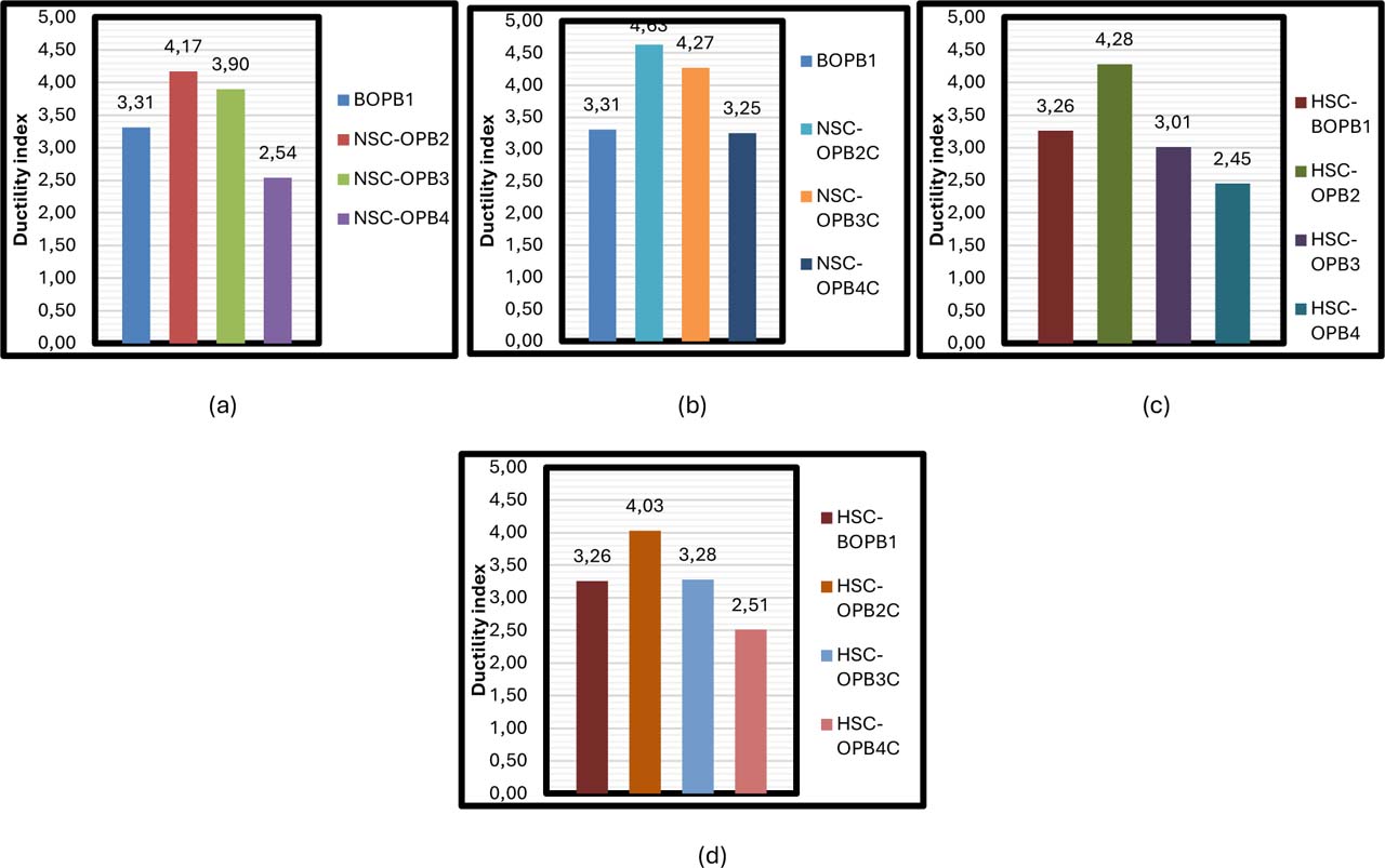
Figure 13:
Ductility index of the OPB beams
6.5. Initial Stiffness
Comparing the initial stiffness (Ki) of the NSC concrete specimens (as exhibited in Fig. 14) with the reference specimen BOPB1, which recorded a value of 20.69 kN/mm. It noted that the NSC-OPB2 specimen recorded a stiffness of 13.65 kN/mm, a decrease of approximately 34%, while the NSC-OPB3 specimen recorded a stiffness of 14.89 kN/mm, a decrease of approximately 28%, and the NSC-OPB4 specimen recorded a stiffness of 14.94 kN/mm, also a decrease of 28%. These decreases reflect the fact that dividing the section into multiple sections reduces the stiffness of the element, due to the negative effect of joints on the resistance to flexion and initial deformation. The NSC-OPB2C, NSC-OPB3C, and NSC-OPB4C composite specimens recorded higher stiffnesses than the reference specimen, reaching 11.22, 17.71, and 13.56 kN/mm, respectively. Although NSC-OPB2C recorded the lowest stiffness, NSC-OPB3C achieved a significant improvement, with a reduction of only 14% compared to the reference. This indicates that the effectiveness of steel reinforcement varies depending on the distribution of concrete components and their integration with the steel. In the case of high-strength concrete, the reference model HSC-BOPB1 recorded an initial stiffness of 20.43 kN/mm. HSC-OPB2 recorded 20.07 kN/mm, a slight decrease of approximately 1.7%. HSC-OPB3 recorded 20.89 kN/mm, a slight increase of 2.2%. HSC-OPB4 recorded 16.95 kN/mm, a decrease of approximately 17%. This indicates that high-strength concrete maintained its stiffness even with some joints, especially in the two-part and three-part models, but performance significantly decreased with four-part models. For the HSC-OPB2C, HSC-OPB3C, and HSC-OPB4C composites, stiffnesses were recorded above the reference values of 25.10, 27.51, and 22.12 kN/mm, respectively, representing increases of 22.8%, 34.7%, and 8.3%. This demonstrates that the use of steel sections within high-strength concrete significantly enhances stiffness, particularly in the HSC-OPB2C and HSC-OPB3C cases, where the integration of high-strength concrete and steel significantly improved structural performance under initial loads.
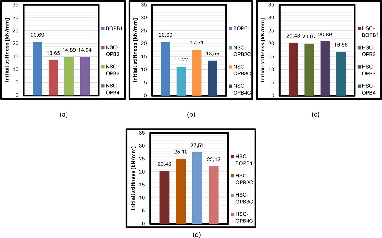
Figure 14:
Initial stiffness of the OPB beams
6.6. Toughness
The cumulative capacity (toughness) of energy absorption for each beam configuration was measured as the area under the load-displacement curve from the moment of loading to the value corresponding to the ultimate load in this study. Numerical calculation of this area was performed by means of the trapezoidal integration rule, written as: where Δ is the deflection at midspan, Δu is the deflection corresponding to the ultimate load and P is the applied load. This technique approximates the continuous load-displacement behaviour by integrating over the successive trapezoids formed between pairs of consecutive data points obtained from the numerical output, giving a very accurate estimate of the total mechanical work absorbed in the beam before failure.
Where:
E – cumulative energy absorption (toughness) [kN·mm],
P – applied load at a given deflection [kN],
Δ – midspan deflection [mm],
Δu – deflection corresponding to the ultimate load,
Pi – applied load at the ith data point [kN],
Pi+1 – applied load at the (i + 1)th data point [kN],
Δi – deflection at the ith data point [mm],
Δi+1 – deflection at the (i + 1)th data point [mm],
n – total number of data points in the load–displacement curve,
i – index of the data point, i = 1, 2, …, n − 1.
This quantity, in terms of energy, corresponds to total elastic strain energy plus plastic (post-cracking) deformation energy and thus serves as a more holistic measure of ductility and durability than the ultimate load by itself an indicator that only describes peak strength without accounting for the structure’s ability to survive deformation (Unver et al. 2026). Comparing the energy toughness values of the NSC plain concrete specimens with the reference specimen BOPB1, which had a strength of 8929.60 kN/mm, we note that the NSC-OPB2 specimen recorded a strength of 8055.30 kN/mm, a decrease of approximately 9.8%. Meanwhile, the NSC-OPB3 specimen recorded a strength of 4814.40 kN/mm, a sharp decrease of 46.1%, and the NSC-OPB4 specimen recorded a strength of 2457.80 kN/mm, a significant decrease of 72.5%. The presence of internal steel section in NSC-OPB2C, NSC-OPB3C and NSC-OPB4C composites resulted in a relatively higher toughness. The world of NSC-OPB2C reached 11,786.00 kN/mm which is an increase of (32%) compared to reference showing that some added section can safely enhance the beam failure load due to its energy absorption capacity ability. The value of NSC-OPB3C was recorded to be 9,004.20 kN/mm which is just higher than the reference by about 0.8% but for that of NSC-OPB4C it was recorded as a decrease of 34.4 over the reference with the value being 5,856.70 kN/mm. This shows that the efficacy of reinforcement diminishes with more reinforcing media and also that load sharing between concrete and steel does not work well in complex structures. For high-strength specimens, the toughness value for reference specimen HSC-BOPB1 was 10693.40 kN/mm. The strength value of the HSC-OPB2 specimen was 9336.90 kN/mm (12.7% loss). However, the strength value for each specimen was reduced as well; HSC–OPB3 recorded only 6906.60 kN/mm with a reduction of 35.4%. In Fig. 13. These results confirm that high-strength concrete, despite its strength, loses its energy absorption capacity as the number of joints increases, and it is naturally more brittle than conventional concrete. In the composite specimens HSC-OPB2C, HSC-OPB3C, and HSC-OPB4C, we find that metal reinforcement significantly increased the strength values. The HSC-OPB2C recorded the highest value of 12,752.10 kN/mm, a significant 19.2% increase over the reference model.
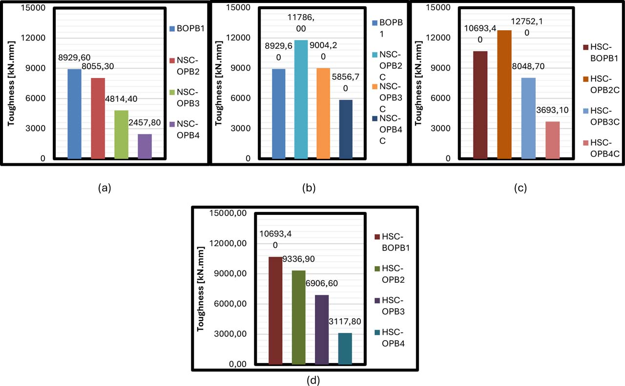
Figure 15:
Toughness of the OPB beams
This is attributed to the S-shape section’s effectiveness in strengthening the beam and enhancing its energy-bearing capacity under loads. The HSC-OPB3C recorded a value of 8,048.70 kN/mm, a 24.7% decrease, while the HSC-OPB4C recorded a value of 3,693.10 kN/mm, a 65.5% decrease as shown in Fig 15. Despite the presence of the steel section, the large number of sections negatively impacted the integrity between the concrete and the steel. In general, the results show that toughness is significantly affected by the number of concrete joints more than any other indicator. The best performance is achieved when sections are minimized and internal integrity is enhanced, with effective support from a steel section to improve energy absorption. Reinforcement is most effective when force distribution is balanced and the number of joints is limited, especially in environments requiring high collapse resistance.
6.7. Cracking Pattern and Stress Distribution
Reinforced concrete beams of various configurations exhibit varying failure mechanisms related to the nature of the stress distribution, the type of concrete used, and the presence or absence of internal steel members, as exhibited in Figs. 16&17. Numerical analysis and stress distribution results provide a deeper understanding of the cracking and failure patterns in these beams. By conventional (straight) concrete beams, the failure mode is characterized by a pronounced flexural failure. Cracks begin at the lower fibres of the beam at the midspan due to the highest moment load in that region. They appear vertical or near-vertical, expanding with increasing load until they reach failure. By straight beams, shear stresses localize around the supports and travels up diagonally (approximately 45°) to the load region which creates a symmetric flexure dominated failure mode. In the case of this last alternative, shear stresses instead concentrate at the discontinuities meshing between segments and spread towards the upper face − leading to more or less oblique cracking subsequently followed by local fragmentation. This is due to the fact that a sudden directional change at each single joint inhibits linear propagation of input forces, thus resulting in spiral torsional moments and internal buckling modes as a natural consequence stemming from the asymmetrical transmission of forces between different vertical planes and reminiscent of an effect not seen in straight beams, where torsion only occurs under asymmetric loading or when subjected to support irregularities. The severity of the failure that rubber can induce is strongly dependent on the type of concrete. High-strength concrete (HSC) can sustain higher level stress but under the condition they are undergoing shear-torsion-flexure together, their brittle behaviour make it susceptible to sudden failure through crushing or bond delamination at the joints without visible warning cracks as compared to normal-strength concrete (NSC). In contrast, NSC shows a more gradual and ductile crack propagation.
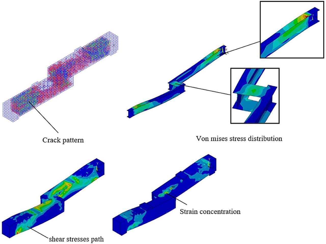
Figure 16:
Cracking mode, stress distribution, and failure mechanism of the NSC-OPB2C beam
This failure mechanism is circumvented by embedding S-shaped steel sections that strengthen the connection zones and enhance inter-segment force transfer, reducing local stress concentration. In the case of steel-encased models, cracking starts later, is smaller and more contained, and failure progresses continuously rather than dynamically – which is particularly true for fewer-segment systems. The rigid moment transmission achieved through the steel section also serves to restrain relative rotation between segments, which helps mitigate buckling effects and improves structural integrity over a larger length of joint while delaying crack initiation.
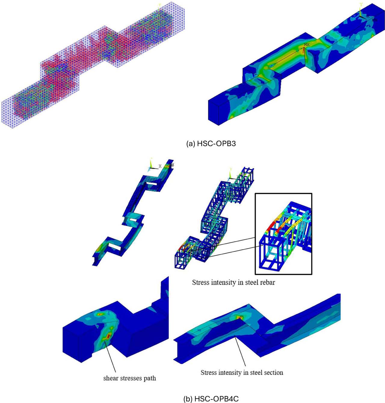
Figure 17:
Cracking mode, stress distribution, and failure mechanism of HSC-OPB beam
Non-coplanar and partially independent segment behaviour generates internal torsional moments that cause irregular helical or warping torsion to propagate around the section axis. These effects are localized to the connections with cross-linear segment displacement mismatch or using high-strength concrete which has low plastic deformation capacity, such as in poorly bonded joints. This results in a three-dimensional tensile-compressive stress state that leads to shear and out-of-plane (oblique or spiral) cracking patterns different from those produced by conventional flexural cracks. The connection zones act like relatively stiff but not fully rigid joints, such that moment and strain transfer between segments is accompanied by local relative rotation, generating asymmetric bending which recursively amplifies the torsional moment. These torsional effects occur in addition to the shear and flexural moments, increasing the demand on the structure and yielding a complex combined failure mode. The deterioration begins locally as either joint rotations with concrete crushing or delamination at the contact interface and may progress to segment separation under combined shear-torsional action. This behaviour is reduced in reinforced (OPBC) configurations due to the embedded steel section, which provides a rigid load transfer path for torsional moment and minimizes sliding and rotation of one segment with respect to another. The steel section works like a big internal structural brace preventing relative torsional rotation, limiting spiral crack development and delaying failure.
7. Conclusion
From the analysis of results generated by models of composite and segmented beams made with normal-strength concrete (NSC) or high-strength concrete (HSC) with and without internal reinforcement made with an S-shape steel section it is possible to expose nine precise scientific conclusions that emphasize these structural aspects.
The beams with internal steel consistently failed at higher ultimate loads and greater displacements than the corresponding unreinforced beams. In the case of NSC-OPB2C and its counterpart without confinement (NSC-OPB2) the ultimate load scaled up from approximately 200 kN. This is due to the fact that, while the flexural resistance is provided by the section of steel (through a composite action), some load can still be sustained after cracking in the concrete phase, which provides a post-cracking response that may not be brittle but ductile which does occurs in non-composite models.
In contrast, the HSC specimens exhibited a peak resistance to early-stage deformation due to their steeper initial load-displacement curves. However, without internal steel reinforcement to avoid post-cracking failure, the well-defined stiffness advantage did not lead to a reliable post-cracking performance – HSC-OPB models without reinforcement (IC HSC-OPB3 & HSC-OPB4) failed suddenly after reaching their ultimate load confirming that ultimate load alone is insufficient for assessing structural performance and that the brittleness of HSC requires compensation by steel reinforcement.
NSC-OPB2, NSC-OPB3 and NSC-OPB4 presented a stepwise reduction in both ultimate load and displacement with each successive segment due to ineffective stress transfer across joints causing weak structural continuity.
In reinforced segmented models (OPB3C, OPB4C), the steel section had a structural bridging action facilitating more uniform load transfer across joints while eliminating the connection zones as a likely point of weakness, which then led to deterioration in unreinforced segmented models.
The combination of NSC (or HSC) with an internal steel section gave a consistent overall performance higher strength, greater ductility, and better joint continuity by exploiting the strengths of concrete in compression together with flexural stiffness and ductility in steel. These results validate the increasingly favourable structural design of composite systems, especially for bending elements under non-uniform or phased loading conditions.
Notes
[1] Author Contributions
M.S.I.A. conceived and designed the study, conducted the experiments, and collected the data. M.A.R. performed the statistical analysis. Z.O.H. contributed to data interpretation and manuscript drafting. All authors critically reviewed and approved the final version of the manuscript and agreed to be accountable for all aspects of the work.
Acknowledgements
The authors acknowledge the academic and technical support received during the preparation of this research. This research received no external funding.