

1. Introduction
Amidst the escalating worldwide demand for energy and the concurrent exhaustion of near-surface resources, harnessing deeper reserves has emerged as an indispensable objective. In high-stress deep settings, the mechanical characteristics and failure behaviors of the encircling rock are profoundly impacted by the alterations in stress regimes triggered by human activities, diverging markedly from those observed in shallower subterranean constructions. Particularly for hard rock masses, engineering activities are prone to induce geological hazards such as fracturing, spalling, large deformations, large-volume collapses, and rockbursts. As underground engineering progresses to greater depths, the secondary disturbance stress on the surrounding rock gradually intensifies, leading to increasingly significant fracture damage effects. For deep rock mass engineering, especially the excavation of large underground projects, the process from start to completion takes a considerable amount of time. The entire process involves gradual excavation and unloading, during which the geometry, physical properties, and boundary conditions of deep buried chambers also change progressively over time. Concurrently, stress redistribution, tunnel excavation induces both inward convergence and fabric restructuring in the surrounding rock mass, resulting in the gradual development and evolution of cracks, joints, and shear fractures around the tunnel. Various fractures gradually aggregate during evolution to form a network of cracks, causing damage to the surrounding rock. To systematically analyze the initiation and progression of various surrounding rock failures in deep excavations, many scholars have started with in-situ observation studies of the mechanical responses of rock masses, such as fracture evolution, stress changes, and volumetric fracturing in deep tunnel surrounding rock, to qualitatively analyze the patterns and mechanisms of various special failure phenomena in deep engineering.
Concerning the evolutionary characteristics of the damage zone in surrounding rock during the excavation of tunnel and underground engineering works, Gao applied an advanced form of peridynamics to investigate the stability of the surrounding rock encountered during tunneling operations (Gao et al, 2020). Through simulation of the excavation damage zone's development patterns around a circular tunnel driven in environments with substantial stress contrasts, they elucidated the correlation between the EDZ's spatial orientation and the principal stress direction. Employing in-situ acoustic wave monitoring of rock masses and numerical simulation techniques, Chen colleagues determined that transient damage induced by excavation unloading is amplified under conditions of elevated confining stresses (Chen et al, 2016). Septiarsilia studied the seismic performance of concrete columns under cyclic loading using the finite element method. (Septiarsilia et al, 2026). Zhang investigate how excavation-related degradation compromises the quality and structural integrity of rock masses, potentially leading to severe stability concerns in deep subterranean environments, and it is revealed via acoustic wave detection and digital panoramic borehole logging that the formation mechanism of the deep excavation-induced damage zone conforms to a stress concentration-dominated pattern (Zhang et al, 2022). Zhou developed a coupled method of peridynamics and finite element method to quickly solve static failure problems. Employing this approach to examine the damage and deformation developmental regularities of surrounding rock, they clarified the distribution characteristics of the EDZ and its deformation regularities in the process of underground chamber group excavation (Zhou et al, 2022). Wang employed a finite fracture approach to investigate the characteristics of on-site earthquake motions. Their findings highlighted how wave velocities within the damaged region dictate the behavior of near-field ground shaking, thereby delivering fresh perspectives on the impact of excavation activities on both the distribution of motions around the site and the resulting damage to surrounding rock fractures (Wang et al, 2021). Wang derived a distinctive energy parameter reflecting unstable fracture damage, and using the variation principle, clarified the correlation between this distinctive energy parameter and the energy grading sequence governing deformation and failure in deep rock masses (Wang et al, 2016). Li leveraging an independently developed microseismic monitoring system, investigated the stability of the surrounding rock and the mechanism of concentrated zone fracturing in the Jinchuan Hydropower Station spillway tunnel. The findings demonstrated that construction procedures and in-situ geological settings represent two key drivers governing the initiation of microseismic events, which also determine their locations to some extent. The concentration of microseismic events and their larger moments can be regarded as indicators of future surrounding rock failure (Li et al, 2022).
Regarding analytical approaches and theoretical investigations into the surrounding rock damage zone in underground construction projects under intricate geological settings, Harrison distinguished between the surrounding rock failure resulting from the inherent instability encountered during excavation and the supplementary degradation instigated by the specific excavation technique utilized (Harrison, 2008). Drawing upon practical engineering case studies, Qian established the concept of zonal disintegration to characterize the damage zone produced by excavation (Qian et al, 2013). Siren pioneered the notion of the excavation disturbed area (Siren et al, 2015). Yang evaluated the mechanical properties of rock masses within the excavation damage zone by applying the Hoek-Brown damage criterion (Yang et al, 2020) (Qu et al, 2021). Fan and Feng further examined how stress unloading trajectories resulting from blasting excavation and tunnel boring machine excavation impact the excavation damage zone, using theoretical and numerical computations (Fan et al, 2021) (Feng et al, 2022). Kulkarni studied the influence of stress on structures in a temperature field based on higher-order plate theory. (Kulkarni et al, 2024). Fattahi et al. employing an integrated methodology that combines Monte Carlo simulation and the adaptive neuro-fuzzy inference system (ANFIS) with subtractive clustering, found that the creation probability of the fracture zone is 0.12, and the creation probability of the excavation damage zone is 0.32, with the EDZ extending between 0.5 to 1 meter (Fattahi et al, 2013). Xu et al. utilizing elastoplastic theory, established a predictive model for EDZ evolution and constructed a tripartite composite mechanical model for the rock mass adjacent to tunnels (Xu et al, 2012). Li et al. leveraging microseismic monitoring datasets, examined the spatial distribution patterns and developmental regularities of the surrounding rock excavation damage zone (Li et al, 2022). Kim et al. via dynamic 3D large-deformation finite element simulations, quantified the spatial scope of the excavation damage zone in strata resulting from shield machine advancement (Kim et al, 2021). Guo et al. introduced a rock mass integrity index using borehole television imaging, tackling the limitation that RQD values fail to precisely characterize rock mass integrity under deep high-stress conditions (Guo et al, 2017). Huang et al. presented an EDZ assessment method founded on the point safety factor (Huang et al, 2022). Xu et al. introduced an integrated predictive approach to quantify the spatial range of the excavation damage zone in brittle surrounding rock of deep underground caverns (Xu et al, 2022). Jiang et al. developed an elastoplastic damage constitutive model rooted in the Hoek-Brown criterion. While a wealth of scholars have carried out extensive investigations into the fracture, influencing factors, and countermeasures for deep rock masses, systematic research methods for understanding the mechanical response and fracture initiation mechanisms of deep rock masses are still lacking under the complex conditions of diverse fracture modes and time-dependent effects (Jiang et al, 2022).
This study integrates in-situ monitoring datasets from underground engineering excavation to examine how excavation techniques impact the fracturing evolution patterns of surrounding rock in deep hard rock tunnels subjected to excavation disturbance, elucidating the behavioral regularities of surrounding rock fracturing and damage throughout the excavation sequence. Using this domestic numerical software CASRock to model stress variations in the tunnel surrounding rock mass, is examined how excavation techniques affect the fracturing evolution patterns and damage mechanisms of surrounding rock in deep hard rock tunnels subjected to excavation disturbance, thus clarifying the developmental regularities of surrounding rock fracturing and damage during excavation activities. This offers practical engineering guidance for mitigating hazards including rockbursts, rock spalling, and excessive surrounding rock deformations triggered by fracturing damage during the excavation of deep hard rock tunnels.
2. Engineering Overview
This research pertains to a substantial underground tunnel venture, characterized by a cover depth of about 2400 meters. The tunnel has an arched cross-section measuring 14 m in both width and height. To examine the fracturing propagation patterns, damage initiation mechanisms, and inherent developmental regularities of the tunnel surrounding rock under such deep excavation conditions, an in-situ monitoring program was implemented. A total of 25 monitoring boreholes were drilled, with data from 22 boreholes evenly distributed across experimental areas 1 to 9 selected for analysis, The drilling layout combines pre-drilling with direct drilling. Pre-drilling involves setting up boreholes in the chamber to be excavated via an auxiliary tunnel excavated in advance, while direct drilling involves setting up boreholes directly inside the tunnel after construction is complete. Boreholes are installed prior to excavation for monitoring purposes, and additional boreholes are progressively added in the fractured zones as excavation proceeds in layers and stages, to determine the impact of the entire tunnel excavation process on the surrounding rock. The specific borehole identifiers used in this monitoring program are C1-1, C2-1, C4-1, C5-1, and C6-1. The corresponding laboratory designations are 1#LAB, 2#LAB, 3#LAB, 4#LAB, 5#LAB, 6#LAB, 7#LAB, 8#LAB, 9-1#LAB, and 9-2#LAB (where “#LAB” denotes the laboratory number). The arrangement of these boreholes is shown in Figure 1, and the surrounding rock mass consists mainly of marble with varying integrity. In such deep excavations under high stress, the relaxation of in-situ stress often induces microcracking in the surrounding rock, which can propagate and form a fractured damage zone, thereby threatening construction safety. Excavation was conducted in two layers using the drill-and-blast technique: the upper layer was constructed by first excavating a central pilot tunnel, followed by expanding the sidewalls, while the lower layer began with a middle trough excavation followed by side expansion, as illustrated in Figure 2.
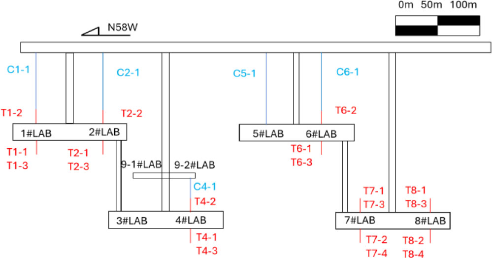
Figure 1:
Drilling layout diagram of laboratory
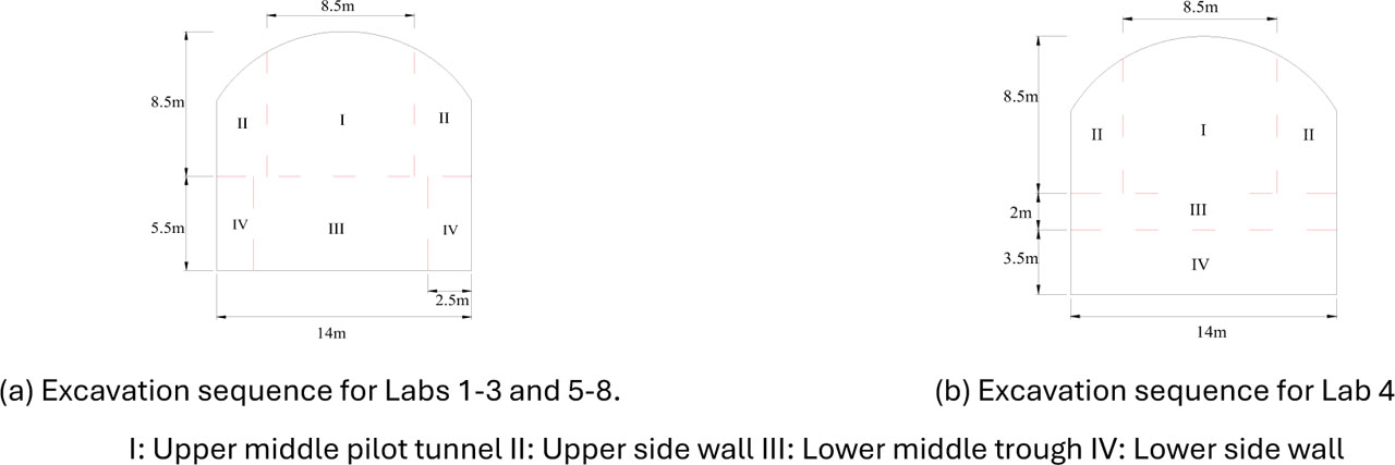
Figure 2:
Schematic illustration of the laboratory excavation steps
3. Influence mechanisms of rock mass damage and fracturing in deep buried tunnels
3.1. Experimental investigation of excavation-induced rock mass damage severity in deeply buried tunnels
To quantify rock mass integrity and provide a quantitative basis for subsequent damage ratio analysis, the RMIBT was adopted in this study. Calculated from borehole camera data, RMIBT reflects rock mass integrity through the weight ratio of crack-free rock segments along the borehole wall, with classification criteria outlined in Table 1.
Table 1:
RMIBT-Based rock mass structure classification standards
| Grade | Rock mass structural types | Rock mass structural characteristics | RMIBT value[-] |
|---|---|---|---|
| I | Highly intact rock mass | Structural planes not developed, spacing > 100 [cm] | 0.9–1 |
| III | intact rock mass | Structural planes slightly developed, generally 1–2 sets, spacing generally 70–100 [cm] | 0.75–0.9 |
| III | Fairly intact rock mass | Structural planes moderately developed, generally 2–4 sets, spacing generally 40–70 [cm] | 0.5–0.75 |
| IV | Poorly intact rock mass | Structural planes poorly or well developed, generally 4–6 sets, spacing generally 20–40 [cm] | 0.25–0.5 |
| V | Broken rock mass | Structural planes extremely developed, spacing generally < 20 [cm] | 0–0.25 |
The time-evolving fracturing mechanism of tunnel surrounding rock following excavation of deep hard rock tunnels was elucidated by leveraging long-term monitoring datasets from the underground research laboratory. Borehole camera tests were conducted at intervals to track crack development: immediately after excavation and two years later (Fig. 3). Initial observations identified multiple preexisting fractures in the rock mass—concentrated at ~0.6 m, 1.2 m, and 2.2 m from the sidewall—attributed to construction-induced stress changes or inherent rock mass structure. A re-survey two years later revealed significant opening of preexisting fractures at 1.2 m from the sidewall (indicating intensified fracturing over time, potentially due to groundwater pressure fluctuations or stratum creep) and numerous new fractures at 0.8 m, linked to stratum stress redistribution or external load changes.
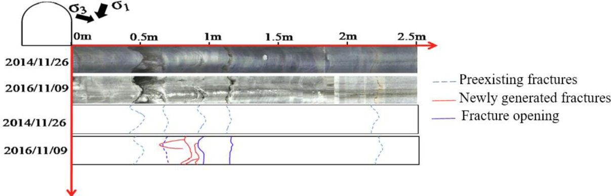
Figure 3:
Comparison of drilling camera results at different times after excavation
To better illustrate the time-dependent nature of fracture evolution, monitoring of the experimental tunnel was conducted at key intervals: 32 days before excavation, followed by 1 day, 3 days, and 690 days after excavation (Figure 4). Prior to excavation, pre-existing fractures were already present. Following excavation, these original fractures expanded considerably due to excavation-induced disturbance. New fractures, initiated around the pre-existing ones, exhibited continuous propagation over time. Notably, time-dependent fracturing was observed even within deep rock masses located far from the tunnel sidewall.
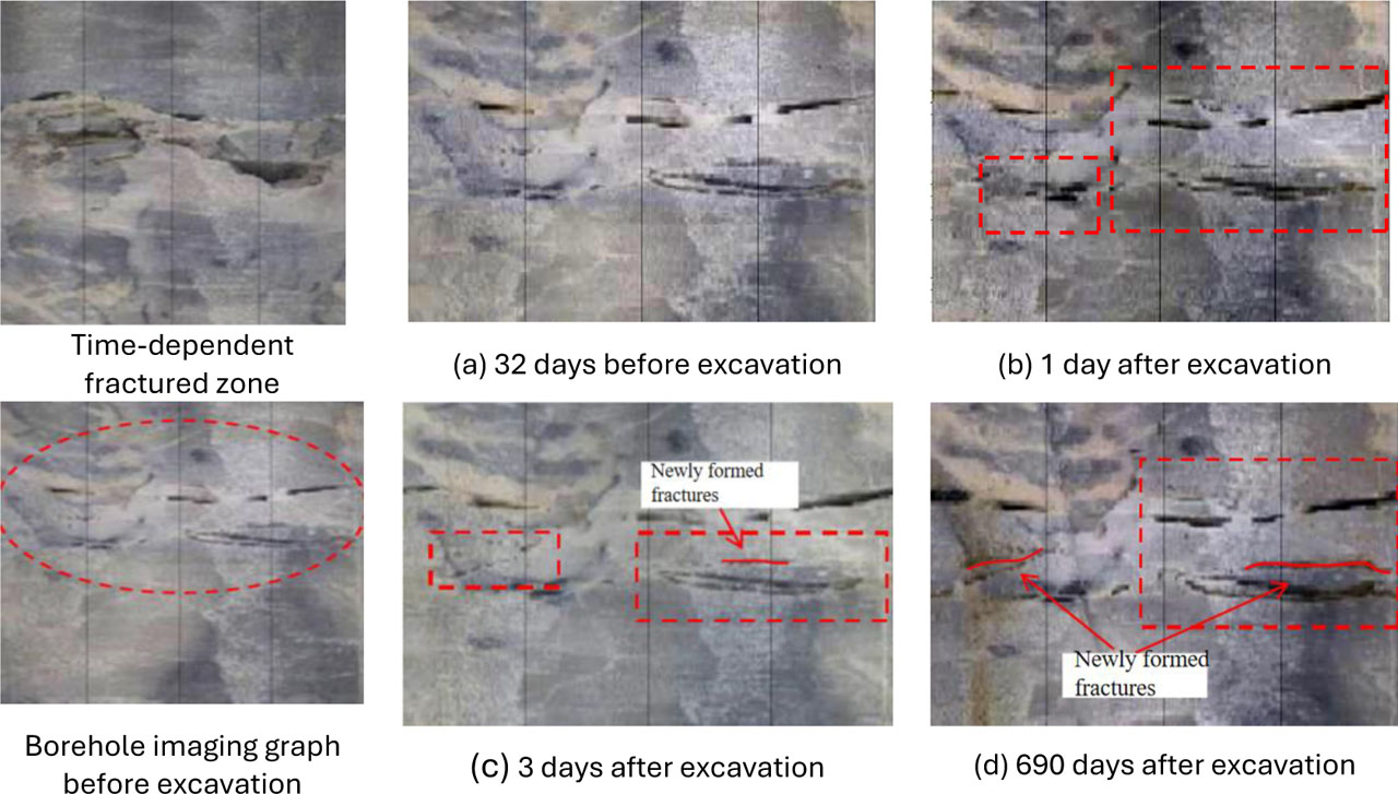
Figure 4:
Fracture aging fracture diagram of experimental chamber with hole depth of 16~18 m
To investigate the causes of the above phenomena, the borehole camera results were integrated with true triaxial test results for analysis. This method involved mapping and comparing time-dependent fracture samples obtained from the field under different stress states with the borehole camera results based on spatial location. The analysis revealed that: In the area near the sidewall (high stress difference zone): rock failure was characterized by the generation of numerous secondary steeply dipping fracture surfaces, with intense time-dependent fracturing phenomena. In the transition zone towards deeper regions: as depth increased (stress difference decreased), the failure mode of hard rock gradually transitioned to shear failure. In summary, the comparative analysis of field borehole camera observations and true triaxial tests preliminarily indicates that the near-surface region of the rock mass, owing to its high differential stress level, is where time-dependent fracturing is more severe.
3.2. Mechanistic analysis of rock mass damage and fracturing in deeply buried tunnels
To quantify the correlation between surrounding rock fracture and damage, the damage ratio R (Guo et al, 2022) was defined as:
Where:R - represents the damage ratio,
HEDZ - represents the depth of the damaged zone,
HHDZ - represents the depth of the fracture zone.
This index directly reflects the relative development of fracture and damage, with a significant correlation to rock mass strength and integrity. Key parameters of four marble types were summarized in Table 2, retaining only data supporting the conclusion. The results show that high-strength and intact rock masses have higher R values, while low-strength and less intact ones have lower R values.
Table 2:
Key parameters of different lithologies
| Lithology | Uniaxial Compressive Strength [MPa] | RMIBT Value [-] | Damage Ratio R [-] |
|---|---|---|---|
| Black-gray striped fine-grained marble | 80–190 | 0.75–0.90 | 1.93 |
| Black-gray fine-grained marble | 150–170 | 0.75–0.90 | 2.01 |
| Gray-white marble | 80–120 | 0.50–0.75 | 1.42 |
| Polychrome marble | 60–120 | 0.50–0.75 | 1.60 |
The depth differences between fracture and damage zones for different rock types are visually presented in Figure 5. High-strength intact rock masses exhibit shallower fracture zones but deeper damage zones, while low-strength less intact ones show the opposite trend—consistent with the variation law of R values.
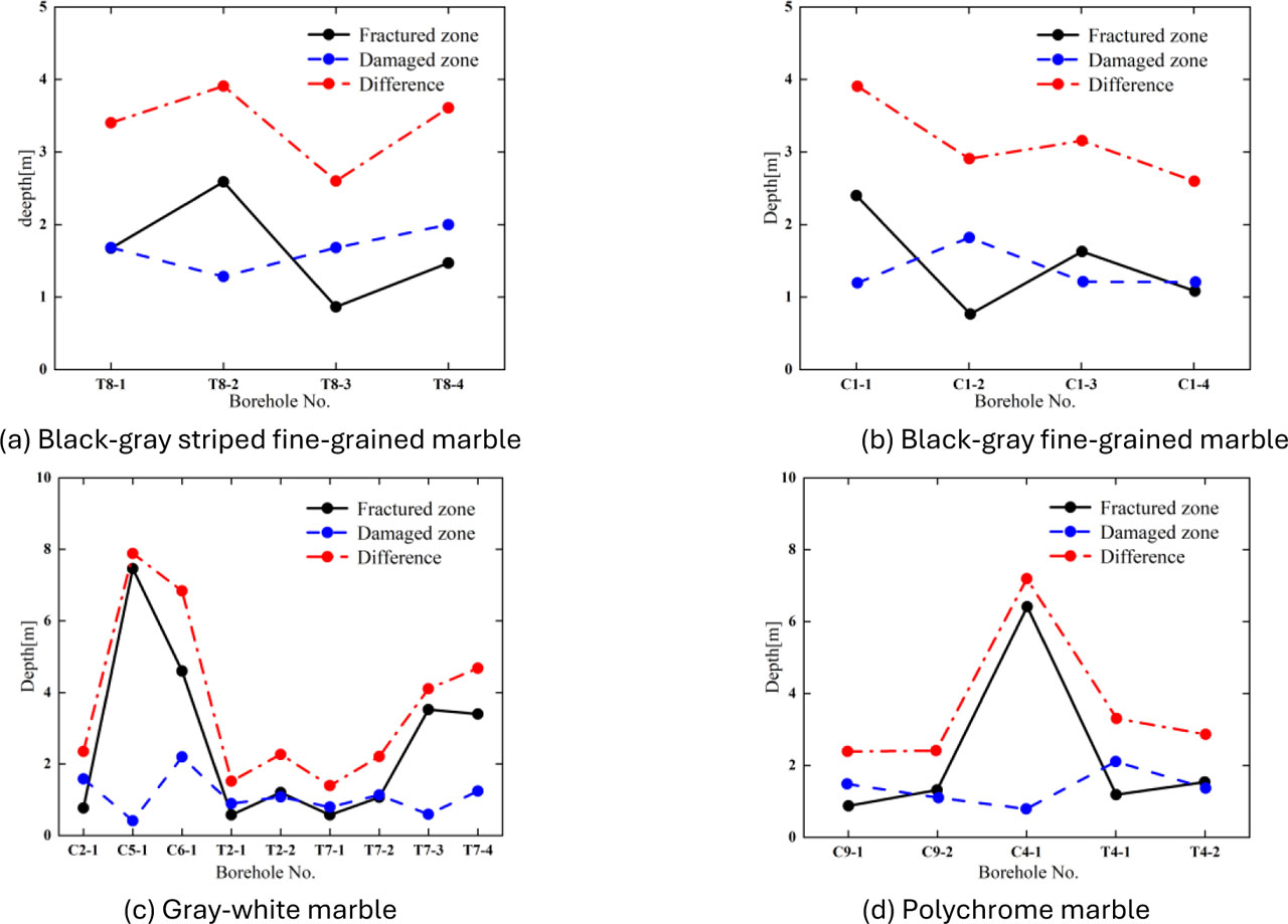
Figure 5:
The rupture zone and damage zone depth of different types of rock mass
In summary, R effectively quantifies the coupling relationship between rock mass properties and fracture-damage characteristics, providing a reliable quantitative basis for surrounding rock stability evaluation.
To elucidate the time-evolving fracturing mechanism of deeply buried hard rock tunnels, the drilling monitoring data of DK194 + 593 and DK194 + 653 sections are selected for comparative analysis. Figure 6 shows the comparison of borehole camera results between 1 month and 1 year after excavation of the underground laboratory engineering section.
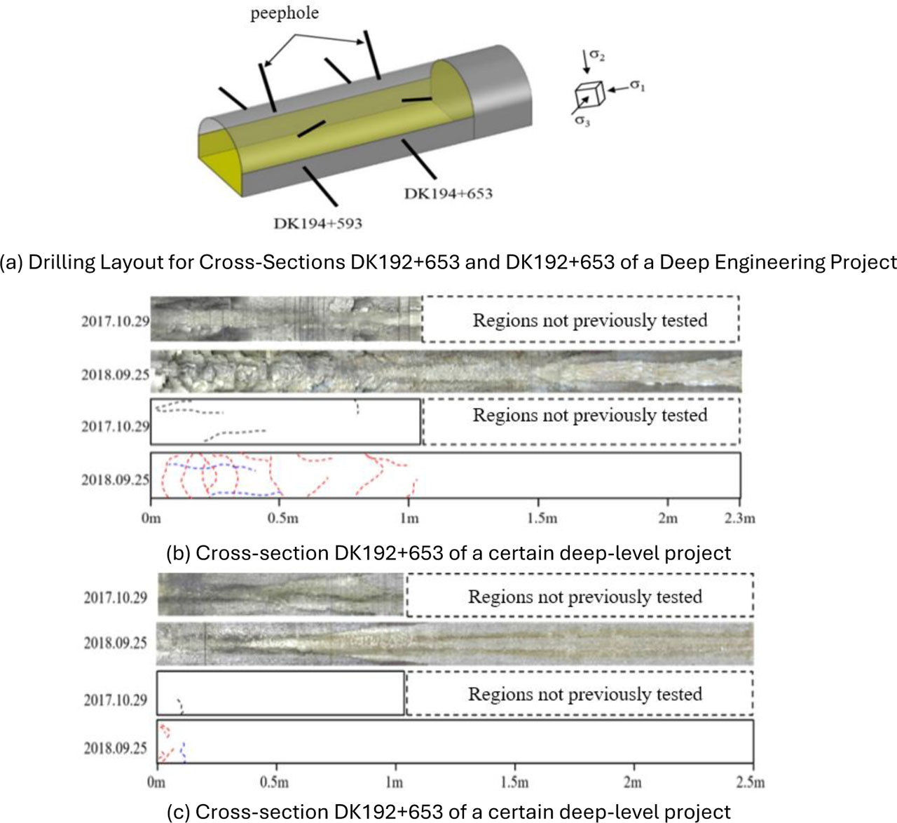
Figure 6:
Borehole camera results of DK194+593 and DK194+653 sections 1 month and 1 year after excavation
Eleven months of rheological time-dependent monitoring of the rock mass at section DK194+653 show that the number of newly generated fractures increases significantly over time, and rock mass integrity continues to decline. This finding verifies that excavation-induced initial damage exerts a dominant regulatory influence on the time-dependent fracturing of tunnel surrounding rock. In contrast, during the same monitoring period, only a small number of minor and gentle fractures developed at section DK194+593, demonstrating good stability. The enhanced stability of this section is tightly linked to the relatively low initial damage incurred during excavation. These comparative findings further validate that the developmental state of pre-existing fractures in the surrounding rock is a critical factor governing the temporal fracturing response of the rock mass.
Based on field monitoring data, at Section DK194+593 one month following excavation, the rock mass maintains relatively high integrity (characterized by a smooth surface and sparse fissures), suggesting negligible initial excavation-induced damage to the surrounding rock. By contrast, at Section DK194+653 one month after excavation, the integrity of the rock mass significantly decreases. Pre-existing fissures have propagated and interconnected, generating several micro-fissures in their vicinity. The emergence of these new fissures suggests continuous development of fractures in the surrounding rock post-excavation, demonstrating evident time-dependent fracturing phenomena. Time-dependent fracturing in rocks primarily occurs in regions with high differential stress and exhibits notable directional characteristics. The fundamental mechanism is that the prevalence of pre-existing cracks in the surrounding rock markedly impairs the rock mass integrity post-excavation, resulting in the development of localized elevated differential stress within the true triaxial stress environment. Driven by this differential stress, initial cracks preferentially propagate along specific dominant directions. These directionally propagating cracks provide pathways for the transport of chemical substances such as groundwater, thereby exacerbating fissure opening reactions (e.g., through stress corrosion effects). Simultaneously, when stress conditions are met, stress corrosion continuously promotes further crack propagation along the established dominant directions. Consequently, the coupling of chemical and mechanical processes not only accelerates the fracturing process but also significantly enhances the inherent directional characteristics of time-dependent fracturing behavior.
4. Regularities of rock mass damage and fracture during deep buried tunnel excavation
4.1. Key indicators of rock mass damage and fracture during deep buried tunnel excavation
5. CASRock numerical simulation software was employed to explore how underground excavation operations influence rock mass fracture patterns. The study centered on modeling the excavation sequence for an underground research facility, with particular attention given to understanding the fracture damage zone development around a deep-buried tunnel. The underground laboratory, measuring 14m by 14m in cross-section, and its corresponding pilot tunnel, sized at 8.5m by 8.5m, were formed via the drilling and blasting technique during their respective constructions. And surrounding rock primarily consists of thick-layered, fine-grained marble with gray and gray-white bands, and the rock mass exhibits relatively good integrity. To ensure the reliability of the simulation parameters, the material composition of the rock samples used in laboratory tests was essentially consistent with that of the on-site rock mass. Based on laboratory tests conducted on intact rock samples collected from the field, the key mechanical property indices of the surrounding rock were derived, as summarized in Table 3 and Table 4.
Table 3:
Key mechanical property indices of surrounding rock mass
| Rock Mass Grade [-] | Elastic Modulus [GPa] | Poisson's Ratio [-] | Tensile Strength [MPa] | Internal Friction Angle [°] |
|---|---|---|---|---|
| Grade II | 29.2 | 0.2 | 1.5 | 30 |
Table 4:
Horizontal stress parameters of surrounding rock
| Horizontal Stress σ1 [MPa] | Horizontal Stress σ2 [MPa] | Horizontal Stress σ3 [MPa] |
|---|---|---|
| 74 | 54 | 36 |
Collectively, Table 3 and Table 4 provide the essential foundational inputs for numerical simulations of deep-buried tunnel performance. Table 3 establishes the key mechanical properties of Grade II surrounding rock, an elastic modulus measured at 29.2GPa, a Poisson's ratio of 0.2, exhibits a tensile strength of 1.5MPa, and features an internal friction angle totaling 30°, which collectively indicate that this rock mass exhibits high strength, high integrity, and robust resistance to both deformation and shear failure.
Table 4 further characterizes the highly anisotropic horizontal stress field of the study area, with principal horizontal stresses of 74 MPa, 54 MPa, and 36 MPa; notably, the maximum horizontal stress exceeds twice the minimum, a stress condition that is a primary driver of fracture and damage in deep rock masses. Combined, these datasets outline the rock mass's intrinsic strength and the surrounding load conditions, thereby providing a rigorous empirical basis for accurately simulating and evaluating the progression of fractures in the adjacent bedrock and the resulting damage caused by tunnel construction.
5.1. Numerical Investigation of Excavation-Induced Rock Mass Damage and Fracturing in Deeply Buried Tunnels
Combined with the field rock mass parameters, the simulation models the construction phase of the subterranean laboratory, with the findings presented in Figure 7.
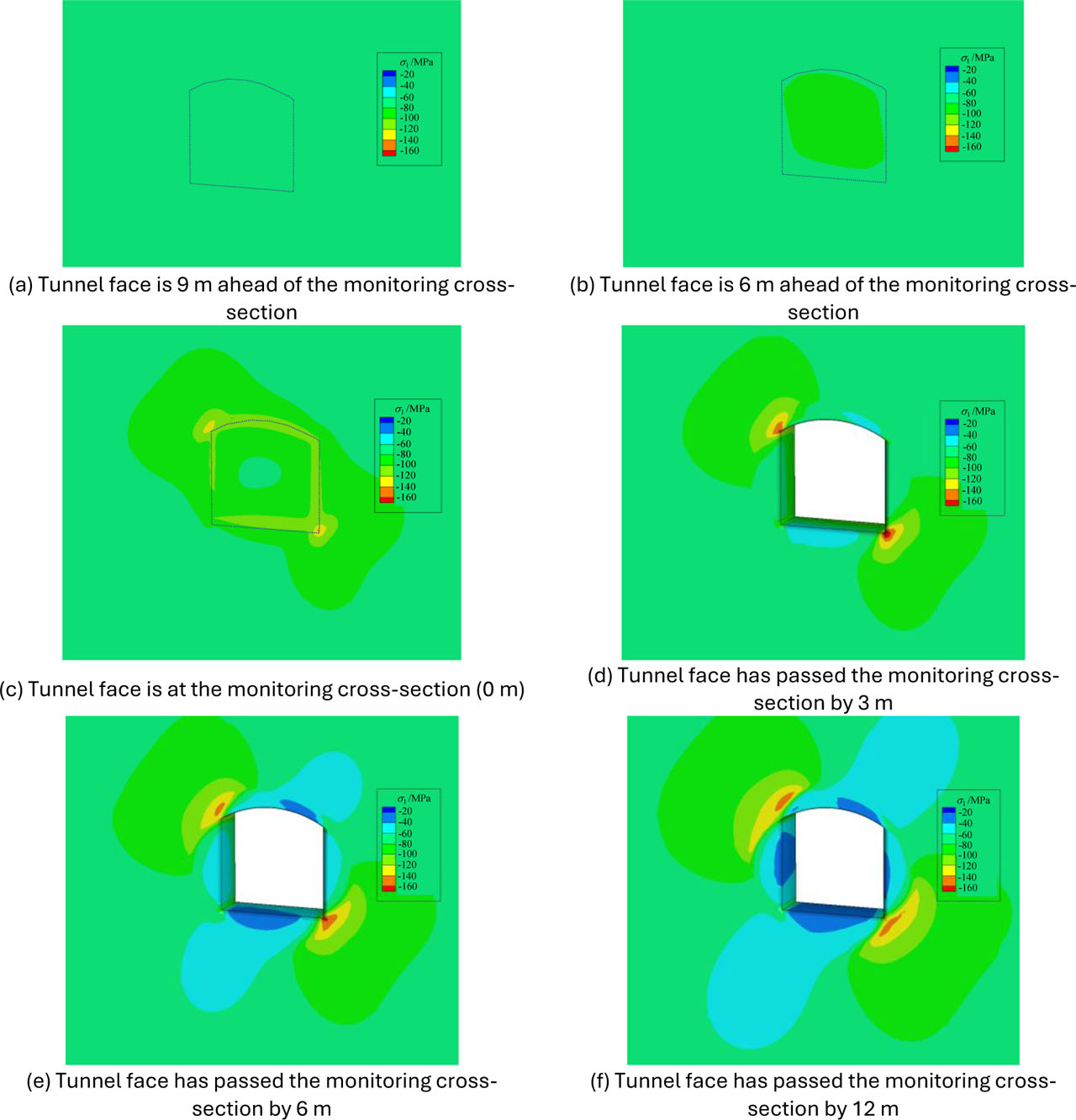
Figure 7:
The stress change of the section was monitored during the excavation
Computational modeling demonstrates that the stresses and damage progression in the strata adjacent to the surveyed section manifest distinct patterns at various stages of the tunneling process. At distances exceeding 9 meters from the excavation face, stress concentrations within the surrounding rock diminish to negligible levels, allowing the native stress regime to remain largely intact, indicating minimal excavation-induced disturbance and negligible impact on fracture development. The surrounding rock material currently exists in an early phase. However, as the tunnel progresses and nears the position of the designated monitoring point by 6 meters, stress concentrations start to develop in front of the excavation face. This signifies the transition of the surrounding rock from its initial state into a developed condition. When the tunnel face reaches the monitoring cross-section (0 meters), significant stress redistribution occurs, with the maximum concentrated stress increasing sharply as the distance decreases. The substantial variation amplitude indicates that the surrounding rock has entered a phase of intense development. Once the tunnel face surpasses the designated monitoring section, extending approximately 3 meters ahead, the maximum principal stress experiences a sustained rise. However, the magnitude of this escalation diminishes noticeably at this stage. This stress change is primarily characterized by a significant expansion of the high-stress zone. At 6 meters past the cross-section, the high-stress zone continues to expand, while the maximum principal stress value experiences a slight decline. A comparative analysis of the simulation findings at 3 meters and 12 meters beyond the point where the tunnel face passes the designated monitoring section reveals that the peak principal stress has reached a stable state. This suggests the surrounding rock transitions into a post-development phase approximately 3 meters subsequent to the tunnel face overcoming the monitoring cross-section. During this stage, the maximum principal stress value shows no significant change.
Based on simulation results and in-situ rock mass characteristics (Section 3.2), three typical fracture modes in the surrounding rock were identified, as illustrated in Figure 8 to Figure 10: Single-zone fracture, characterized by crack propagation from the surface to the interior, is primarily observed in Grade III rock masses (RMIBT 0.50–0.75; e.g., gray-white marble) and corresponds to a relatively low damage ratio R (1.42–1.60); Zoned fracture, involving crack expansion from the interior toward the surface, predominantly occurs in Grade II rock masses (RMIBT 0.75–0.90; e.g., black-gray striped fine-grained marble) and is associated with a high damage ratio R (1.93–2.01); Deep-seated fracture, which manifests as localized cracks in deep, high-stress Grade II rock masses and shows no connection to fractures near the excavation surface.
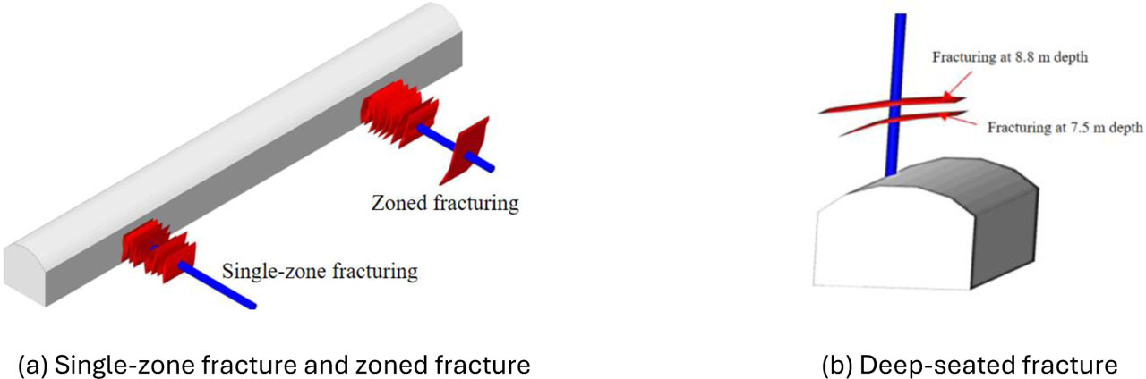
Figure 8:
Schematic diagram of deep rock mass rupture pattern
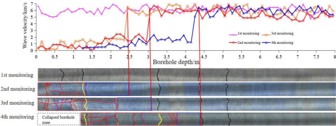
Figure 9:
The maximum concentrated stress changes with the propulsion of the palm surface
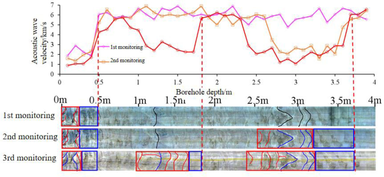
Figure 10:
The location of peak stress migrates following the advancing excavation face.
The behavior and deterioration patterns of the nearby rock mass evolve through four distinct phases, as illustrated in Figure 11. Initially, as depicted in Chyba! Nenašiel sa žiaden zdroj odkazov.(a), when the tunnel entrance is situated over 9m from the surveyed area, the impact is negligible and the native stress conditions remain largely intact. As the face approaches to within 6–9 m (0.5–0.7 times the tunnel diameter), the onset development stage begins, as shown in Chyba! Nenašiel sa žiaden zdroj odkazov.(b), marked by stress concentration and the initiation of microcracks. The process enters an intensive development stage, as illustrated in Chyba! Nenašiel sa žiaden zdroj odkazov.(c), with the face located 0–6 m ahead of the section, characterized by sharp stress redistribution, rapid fracture propagation, and the expansion of the excavation damage zone (EDZ). Finally, after the face has passed the section by approximately 12 m (about one tunnel diameter), the termination development stage is reached, as depicted in Figure. 11(d)above(c), at which point the stress field stabilizes and the EDZ extent stabilizes at a fixed value.
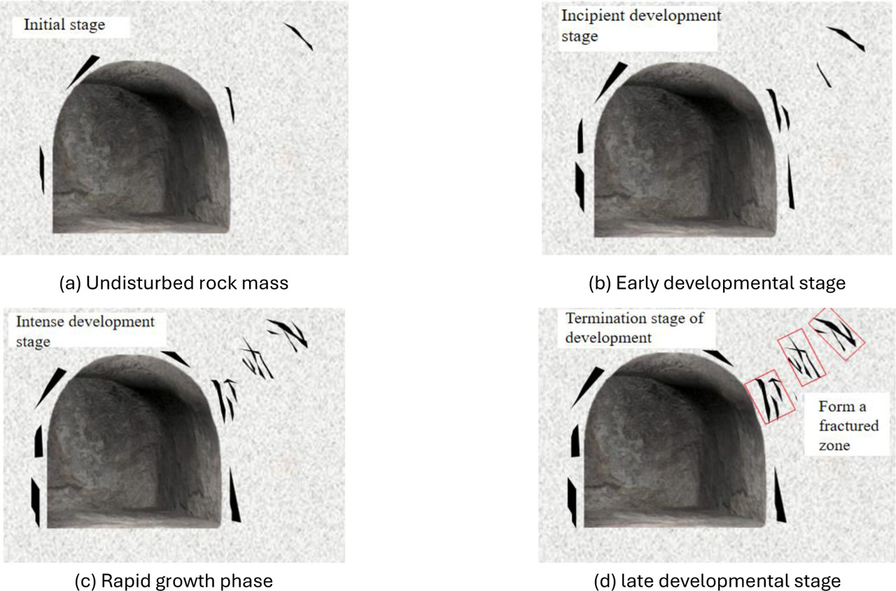
Figure 11:
Breeding process of deep surrounding rock fracture zone
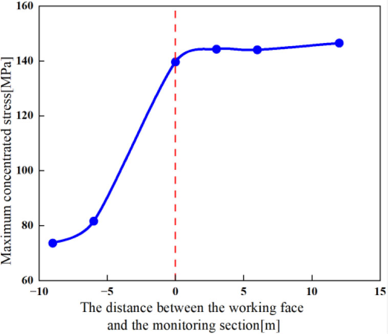
Figure 12:
The maximum concentrated stress changes with the propulsion of the palm surface
Figure 12 displays the characteristic curve that details how the peak concentrated stress fluctuates in relation to the separation distance between the excavation front and the observation section. The computed simulation findings are consistent with the actual field measurements, validating the association between the scale of the surrounding rock distress area and the diameter of the tunnel. The tunnel spandrel and haunch areas are identified as the zones of maximum principal stress concentration, and this stress continues to increase with ongoing excavation. Therefore, during the construction of deep engineering projects, based on geological survey results, implementing advanced support or rock mass reinforcement measures specifically targeting the spandrel and haunch areas of sections with potential high rockburst risk can effectively mitigate the risk of rockburst.
6. Conclusions
Through the integration of on-site observations and computational modeling within a subterranean research facility, this investigation delineates the predominant elements affecting the security of the encircling rockmass in profound hardrock tunneling excavations. Furthermore, apart from the impact of excavation activities, the temporal nature of fracturing processes within the surrounding rock mass and its inherent strength parameters play critical roles. The findings reveal that:
(1) Time-dependent rock fracturing primarily occurs in areas with high differential stress and exhibits significant directionality. The mechanism is that after excavation, both pre-existing and newly generated fractures develop within the surrounding rock. Under a true triaxial stress field, this creates high differential stress, which drives the initial cracks to propagate along specific orientations. When the stress level reaches a critical value, stress corrosion effects facilitate the continuous directional propagation of cracks, thereby intensifying the directional characteristic of time-dependent fracturing.
(2) The rock mass damage ratio is significantly correlated with its strength and integrity. For high-strength, intact rock masses (Grade II, RMIBT 0.75–0.90), excavation induces stress concentration around the opening, triggering new fractures that extend inwards. In contrast, for low-strength, fractured rock masses (Grade III, RMIBT 0.50–0.75), the dominant failure mode is the expansion of pre-existing fractures.
(3) The tunnel spandrel and haunch are the zones of maximum principal stress concentration during excavation, and this stress continues to accumulate with advancing excavation. For sections with potential high rockburst risk, implementing advanced support or rock mass reinforcement measures in these specific areas can effectively reduce the probability of rockburst and enhance construction safety.
(4) Three typical fracture modes of surrounding rock are identified: single-zone fracture (surface-to-interior propagation, dominant in Grade III rock masses), zoned fracture (interior-to-surface expansion, prevalent in Grade II rock masses), and deep-seated fracture (localized deep cracks in high-stress Grade II rock masses). These modes are regulated by the coupling of rock mass properties and excavation-induced stress redistribution.
(5) The excavation damage zone (EDZ) evolves in four stages with clear quantitative thresholds: initial stage (tunnel face > 9 m from the monitoring section), onset development stage (6–9 m ahead, 0.5–0.7 times tunnel diameter), intensive development stage (0–6 m relative to the section), and termination stage (tunnel face passing by ~1 time tunnel diameter). These thresholds provide quantitative references for optimizing excavation speed and support timing.
Acknowledgements
This work was financially supported by National Natural Science Foundation of China (No. 51568020).
Notes
[1] Contributed by Author Contributions
C.B.Q.: Original draft, Figure, Finite element analysis. H.S.G.: Verification, Revision.