

1. Introduction
The shift towards greener and more efficient energy production, together with stricter emission limits, has fundamentally changed the thermochemical operating environment in industrial stacks. The introduction of flue gas desulphurisation (FGD) technologies has shifted the standard operating procedure from a “dry” to a “wet” stack. In these modern configurations, the flue gases are significantly cooled and often fall below the acid dew point before entering the stack. This results in the continuous formation of highly corrosive mists and liquid phases on the inner surfaces of the liner. As a result of the persistent moisture, an environment is created that allows and serves as a transport medium for sulphate ions and hydrogen ions, facilitating their deep penetration into the reinforced concrete matrix. As the alkalinity of the concrete is neutralized, the passivation layer of the internal steel reinforcement is disrupted, triggering a cycle of widespread damage and structural weakening that challenges traditional maintenance paradigms for coal-fired power plant infrastructure. The authors address the issue of concrete corrosion in aggressive environments (Allahverdi & Skvara, 2000), (Scrivener et al. 1997) and corrosion of reinforced concrete structures (Guofu, 2022).
Modern reinforced concrete chimneys in the energy sector (coal-fired power plants) use the principle of a spaced protective sleeve, where a ventilated gap is created between the reinforced concrete structure of the chimney shaft and the flue gas duct. The flue gases are discharged through a ceramic protective sleeve, or a steel or composite liner. The ventilated gap is intended to ensure that, in the event of minor ingress of aggressive condensate from the flue gases into the intermediate space, the condensate dries out due to air circulation, preventing damage to the chimney’s load bearing structure. The usual temperature in the space between the chimney walls ranges from 25 °C to 45 °C, depending on outdoor climatic conditions. However, long-term experience shows that these supporting elements still degrade. In cases of more significant condensate ingress, structural damage can reach a critical stage within just a few months or years (Vonka, 2014), (Ma et al., 2025), (Huang et al., 2023).
Sulfates are the primary factor contributing to degradation caused by desulfurization condensate. Condensate with a pH below 1.5 can essentially be considered sulfuric acid with a concentration of around 2%, (though it also contains a variable mix of other trace elements). The effect of sulfuric acid on concrete is highly destructive. Both the cement paste and the reinforcement bars degrade, resulting in a loss of structural strength. The acid also affects the aggregate in the concrete, although its resistance is generally much higher than that of the minerals in the cement paste. Furthermore, due to the use of limestone in flue gas scrubbing, gypsum often forms in the condensate. Gypsum is associated with volume expansion, which creates highly porous structures, leading to structural damage and the formation of microcracks. Other sulfate minerals, such as ettringite or thaumasite, may also form, but their occurrence directly in the chimney’s interstitial space is unlikely - provided the chimney is in operation (Rasheed et al., 2022), (Kurdowski, 2013), (Pesata et al., 2020).
Based on the information provided, a potential research area was created includet protection of concrete structures, where they are elected four materials, which also includes a screed based on slag sulfate cement (SSC), sulfate-resistant cement (SV), epoxy concrete (EPX), and ultra-high-performance concrete (UHPC). The issue of use and application solutions, including durability, for UHPC and HPC is receiving great attention in research, where interesting experimental programs include (Peknikova et al., 2025), (Mark et al., 2024) and (Ismaeel et al., 2022).
2. Environmental Assessment of the Chimney and Condensate Analysis
2.1. Visual Examination of the Chimney Interstitial Space
A chimney from a brown coal power plant equipped with a wet flue gas desulfurization system was selected as the primary natural environment for this study. This modern chimney was constructed in the late 1990s, with a transition to a different desulfurization method occurring in 2015. The new wet flue gas desulfurization process involves, in simple terms, spraying the flue gas with a lime solution. Sulfates in the flue gas bind to the solution, forming synthetic gypsum. This is a highly effective method that removes up to 95% of sulfates. However, a drawback of this technique is that it causes significant cooling of the flue gas, leading to condensate formation (Pesata, 2024), (Pesata et al., 2020).
A visual inspection of the chimney was conducted in 2020, revealing that the interstitial space was in a state of considerable deterioration, exhibiting numerous significant defects. During operation, condensate is known to penetrate the protective casing and expansion joints, subsequently causing degradation of the affected structures within the interstitial space. The most severely affected element is the inner base, composed of prefabricated reinforced concrete blocks. These concrete blocks have undergone advanced degradation, with material loss and exposure of the concrete aggregate structure to depths of up to 120 mm. This represents a substantial impairment of the supporting structure (Pesata et al., 2020), (Pesata, 2024).
Selected photographs from the diagnostics are shown in Figure 1.
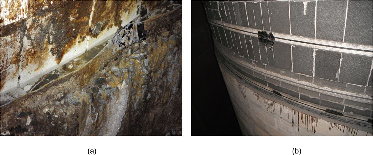
Figure 1:
Comparison of damage on the upper edge in 2020 (a) with the intact condition in 2012 (b) (Pesata, 2024)
2.2. Chimney Diagnostics – Conducting Strength Tests
A detailed survey of the affected structure was subsequently carried out, during which samples were collected for strength testing and laboratory analysis of the concrete. The samples were obtained using a core drilling rig equipped with drill bits of different diameters, specifically 107 mm and 112 mm. The samples were evenly distributed along the height of the structure. The collected specimens were then subjected to destructive compressive strength testing using a testing press. This process included sample preparation and recalculation in accordance with standard requirements. The strength of the prefabricated blocks, as specified in the original project documentation, corresponds to today's C 20/25 class, i.e., a compressive strength of 25 MPa.
The lower part of the structure exhibits strength roughly consistent with the design documentation. Samples taken between approximately +12.000 mm and +20.500 mm show strength values of about 20 MPa after conversion according to applicable standards, indicating an approximate 20% reduction in strength. However, strength values in the upper part of the base, from +21.500 mm to +22.500 mm, are significantly lower, reaching only around 10 MPa after recalculation per relevant standards. This represents a strength reduction of over 60% relative to the original value. The concrete in the upper section also shows signs of material loss. A detailed distribution of samples and strength results is presented in the Table 1 below.
Table 1:
Determination of the strength of individual samples along the height of the base (Pesata, 2024)
| ID / Elevation [m] | Compressive strength [MPa] | Corrected cube compressive strength [MPa] | Recalculated per ČSN EN 13791 |
|---|---|---|---|
| Z1 / + 8.0 | 29.7 | 33.4 | C 20/25 |
| Z2 / + 12.0 | 23.8 | 26.8 | C 16/20 |
| Z3 / + 16.0 | 20.6 | 23.4 | C 16/20 |
| Z4 / + 19.0 | 22.3 | 24.8 | C 16/20 |
| Z5 / + 20.0 | 22.8 | 25.7 | C 16/20 |
| Z6 / +20.5 | 18.5 | 20.6 | C 16/20 |
| Z8 / +21.0 | 13.4 | 15.1 | C 8/10 |
| Z9 / +21.0 | 14.9 | 16.7 | C 8/10 |
| Z10 / +22.5 | 14.6 | 16.4 | C 8/10 |
| Z12 / +22.5 | 13.7 | 15.8 | C 8/10 |
2.3. Chemical analysis of incrustations
To accurately map the environment within the interstitial space of the desulfurization chimney, condensate samples were also collected in the form of already solidified incrustations—newly formed deposits on the outer surface of the protective casing masonry. The incrustations are shown in the Figure 2 below. For subsequent laboratory analysis, the solid components of the samples were first processed. The material was initially crushed using a mortar, then further ground in a laboratory mill. The resulting sample was then passed through a standard set of sieves. Laboratory tests were carried out on the fraction that passed through the 0.063 mm sieve (ČSN EN12390-3, 2009).
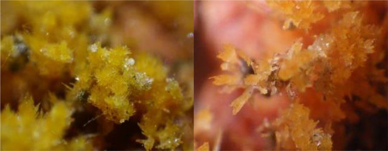
Figure 2:
Microscopic image of incrustations collected during condensate analysis (Pesata, 2024)
pH Measurement and Sulfate Content Determination in Leachate
As part of the incrustation analysis, the pH value was determined first. A solution was prepared from the ground sample using demineralized water in a 1:5 ratio. The mixture was stirred for 24 hours in a laboratory shaker. The solution was filtered through paper, and the filtrate's pH was then measured using a Milwaukee MW 100 pH meter. The measured pH value fell within a very acidic range, specifically between 1.2 and 0.9.
Subsequently, the sulfate content was determined using Quantofix indicator papers. The papers reached the upper limit of their measurement range, indicating a concentration greater than 1600 mg/L (Pesata, 2024).
XRF Chemical Analysis
The undersized ground fraction of the sample was analysed using X-ray fluorescence (XRF) spectrometry. For this analysis, a Niton XL3t spectrometer manufactured by Thermo Scientific was used. XRF spectrometry operates by irradiating the sample with a beam of X-rays, which excites electrons in the atoms to a higher energy state. As the excited electrons return to their original energy levels, characteristic secondary (fluorescent) X-rays are emitted. These are detected and analysed to determine the elemental composition of the sample.
The spectrometer is capable of identifying individual chemical elements and estimating compound concentrations based on preset calibration modes. The analysis revealed a high sulfur content in the sample, comparable to that typically found in gypsum. The sulfur concentration was determined to be 15.09%, which is considered notably high (Pesata, 2024).
DTA (Differential Thermal Analysis) chemical analysis
The sample was subsequently tested using thermal analysis, specifically through combined differential scanning calorimetry and thermogravimetry (DSC/TG). An SDT Q600 device manufactured by TA Instruments was used. The sample exhibits a distinct peak at approximately 70 °C, which can be attributed to the release of residual moisture. Theoretically, this peak could also correspond to the reaction of thaumasite (CaSiO3·CaSO4·CaCO3·15H2O). However, due to the stable year-round temperature of approximately 25 °C in the interstitial space, the presence of thaumasite is unlikely. The occurrence of ettringite (3CaO·Al2O3·3CaSO4·32H2O) is also improbable, as this mineral is unstable at low pH levels and tends to transform into gypsum. The most significant peak is observed between 120 °C and 150 °C, corresponding to an intense reaction of sulfates in the form of gypsum (CaSO4·2H2O). The analysis confirmed that sulfates at concentrations exceeding 35% were successfully removed. Preliminary findings also indicate the onset of minor decomposition of portlandite (Ca(OH)2) at temperatures around 400–450 °C. Simultaneously, evidence of calcite (CaCO3) decomposition was found in the range of 600–700 °C (Pesata et al., 2020), (Pesata, 2024). The results are graphically displayed in Figure 3.
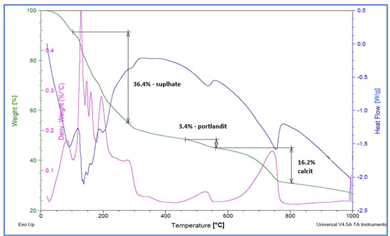
Figure 3:
The resulting reactions of the incrustation sample, as determined by a combination of DSC and TG methods (Pesata, 2024)
3. Protection of structures within chimney interstices
3.1. Current State
The ideal scenario can be considered one in which all load-bearing structures within the chimney’s intermediate space are adequately protected against potential condensate penetration already during the construction phase Historically, Czech standards for the construction of reinforced concrete chimneys have lacked relevant recommendations, guidelines, or regulations regarding the application of protective materials. In the vast majority of chimneys with an intermediate space built in the Czech Republic at the end of the last century, no protection—such as paint coatings or protective plaster—was applied to the inner wall of the shaft or to the inner reinforced concrete supporting structure. Protective coatings on the inner surface are typically only found in chimneys that have been retrofitted with a flue liner in recent years (Ma, 2025), (Pesata et al., 2019).
According to CICIND (the International Association for Industrial Chimneys), the inner surface of the chimney shaft within the intermediate space should be treated along its entire height with protective system B, consisting of a two-component polyurethane coating. As a result, the requirements for the inner surface are significantly more stringent than those for the outer surface (Pesata et al., 2019).
3.2. Protective Materials
As part of research into potential countermeasures against the identified effects of condensation, the use of protective coatings composed of various materials was considered. These coatings would be applied directly to the affected concrete structures. Another option involves protective plasters; however, these generally have a shorter service life compared to coatings and are also difficult to apply to structures that are already contaminated or damaged. Ideally, plasters should be applied as an additional reinforcing layer over the protective coating (Pesata, 2024), (Pesata et al., 2019). A total of four materials were selected for further investigation: a screed based on slag sulfate cement (SSC), sulfate-resistant cement (SV), epoxy concrete (EPX), and ultra-high-performance concrete (UHPC).
Protective Screed Based on Supersulfated Cement (SSC)
Supersulphated cement (SSC) is a hydraulic binder (ČSN EN 15743, 2015) composed primarily of ground granulated blast furnace slag and calcium sulphate. Portland clinker, in its conventional cement form, is included in the mixture and serves as an activator of the latent hydraulic properties of the slag. Additional supplementary components are also incorporated. The main advantage of this binder lies in its improved resistance to chemically aggressive liquids. Granulated blast furnace slag was sourced from the manufacturer Kotouč Štramberk. A by-product obtained after desulphurisation at the coal-fired power plant in Ostrava-Třebovice (part of the Veolia Group) was used as the sulphate component. A small amount of CEM I 42.5R cement and fly ash were added to the resulting binder mixture, along with water. The exact composition of the proposed mixture is presented in Table 2 (Pesata, 2024), (Bilek et al., 2022).
Table 2:
Material composition of individual samples (Pesata, 2024)
| Quantity of Raw Materials per 1 L of Mixture [g] | ||||
|---|---|---|---|---|
| Material | SSC | SV | EPX | UHPC |
| Finely ground blast furnace slag | 425 | 350 | x | x |
| Desulfurization product | 143.8 | x | x | x |
| Fly ash | 12.5 | x | x | x |
| Cement CEM I 42.5R | 12.5 | 150 | x | 650 |
| Silica sand | 1787.5 | 1500 | 1000 | 1330 |
| Water | 243.8 | 195 | x | 150 |
| Plasticizer – Glenium 300 | x | 7 | x | x |
| White microsilica | x | x | x | 70 |
| Ground limestone, grade 8 | x | x | x | 80 |
| MasterGlenium ACE 300 | x | x | x | 26 |
| CHRYSOFluid Optima 185 | x | x | x | 13 |
| Epoxy resin CHS-EPOXY 517 | x | x | 100 | x |
| Hardener Telalit 0846 | x | x | 44 | x |
Protective Screed Based on Sulfate-Resistant Cement (SV)
Sulfate-resistant cement (SV) is a hydraulic binder characterized by its high resistance to aggressive substances in the form of sulfates, whether in solid, liquid, or gaseous phases. The presence of slag in the cement has been shown to result in a slower strength development and a corresponding reduction in the heat released during hydration. Sulfate-resistant cement can be classified within the CEM III category, which includes cements incorporating blast furnace slag. According to current normative standards, sulfate-resistant CEM III cement is further divided into two subtypes: CEM III/B SV, containing 66% to 80% finely ground blast furnace slag and 20% to 34% clinker, CEM III/C SV, containing 81% to 95% slag and 5% to 19% clinker. The cement used in this research corresponded to the CEM III/B SV subtype (ČSN EN 72 2103, 2002).
In this study, sulfate-resistant cement was produced by blending ordinary Portland cement (CEM I 42.5R) with finely ground granulated blast furnace slag supplied by Kotouč Štramberk. The selection of filler type and dosage was based on relevant standards governing cement strength testing and mortar beam evaluation. The detailed mix composition is provided in Table 2 (Pesata, 2024).
UHPC concrete-based protective screed (UHPC)
Ultra-high performance concrete (UHPC) is a concrete that is characterised by its extreme strength and resistance to mechanical damage. Current standards do not provide a precise definition or strength limits, but it can generally be assumed that their compressive strength should exceed strength class C 100/115, i.e. the maximum value according to ČSN EN 206+A2. In general, the compressive strength of UHPC concrete is in excess of 110 MPa (What is UHPC, 2023), (Kravanja et al. 2024). As part of the research, UHPC was prepared using CEM I 42.5 R cement as the binder. The mixture included additives such as white microsilica and ground limestone. Additionally, the superplasticizers MasterGlenium ACE 300 and ChrysoFluid Optima 185 were incorporated. Tovačov sand with a grain size fraction of 0/4 mm, along with water, were used as fillers. The exact composition of the mixture is provided in Table 2 (Pesata, 2024).
Protective Coating Based on Epoxy Concrete (EPX)
Epoxy concrete is classified as a type of polymer concrete, which, unlike traditional concrete, uses an organic polymer-based binder instead of cement. The aggregate filler is similar to that used in conventional concrete, with a focus on achieving the smoothest possible gradation curve, primarily to minimize polymer consumption for cost efficiency. Various polymers can serve as binders, with polyester, epoxy, vinyl ester, and polyurethane being among the most common. Generally, polymer concretes are known for their excellent adhesion to other materials (assuming the substrate is properly prepared), high mechanical strength, elevated compressive strength, long-term durability, and strong resistance to aggressive chemicals, saline solutions, oils, and lubricants. Proper surface preparation is essential for successful application. When applied onto concrete substrates, the surface must be completely dry, clean, free of grease, dust, loose particles, and cement residues (Kim, 2014), (Figovsky, 2013).
As part of the research, epoxy concrete was selected as a representative of polymer concretes. It was prepared using a two-component epoxy resin, CHS-EPOXY 517 (CHS-EPOXY 517, 2023), supplied by Spolchemie, with Telalit 0846 hardener. The ratio of epoxy resin to hardener, as well as the proportion of sand in the overall mixture, is provided in Table 2 (Pesata, 2024).
Sample preparation
For all samples where sulfate-resistant and slag sulfate cement were used as binders, the mixtures were prepared using a laboratory mixer designed for cement beams, operating with a preset mixing program for cements. UHPC concrete was mixed in a larger laboratory mixer intended for concrete mixtures. Prior to mixing, both mixers and all containers were thoroughly cleaned and moistened.
The two-component epoxy mixture was prepared following the procedure outlined in the manufacturer’s application sheet. Mixing was performed in a plastic construction bucket using a spiral mixer attached to a handheld cordless drill. Before mixing commenced, the inner surfaces of the bucket and mixer were inspected to ensure they were dry and free of dust or contaminants. All mixing was conducted in a dry environment at a temperature of approximately 22 °C (CHS-EPOXY 517, 2023).
All test specimens with cement-based binders for the subsequent phase of the research were fabricated as standardized test beams measuring 40 mm × 40 mm × 160 mm. The beams were cast using a standard steel mold designed for three beams. Before filling, the inner surface of the mold was coated with a thin layer of mineral oil, and any excess oil was removed by inverting the mold. The mold was filled immediately after the mixing process was completed and then covered with a glass plate. The prepared molds with plates were placed horizontally in a humidity chamber for 24 hours, except for those containing epoxy concrete, which were left to cure in a dry laboratory environment at approximately 22 °C. After 24 hours, the beams were demolded. The demolded beams were marked accordingly. Epoxy beams were left to dry in the laboratory environment, while the remaining beams were submerged in a water bath (ČSN EN 196-1, 2016).
Exposure of samples to aggressive environments
The prepared samples were tested directly in the chimney space, i.e., in the intended environment. The samples were left in the chimney space for six months. Figure 4 show view of the samples in the interspace after six months of exposure (before decontamination). Subsequently, tests were carried out to determine their tensile strength in bending and compressive strength. Based on the decrease compared to the reference samples, the resistance of the specific material was then assessed (Pesata, 2024).
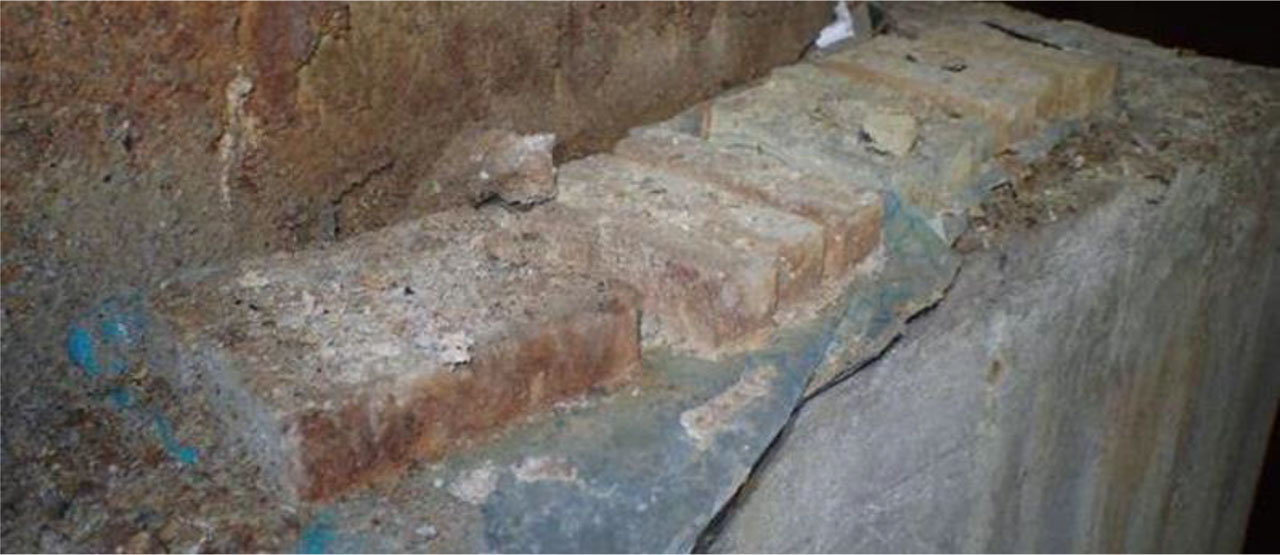
Figure 4:
View of the samples in the interspace after six months of exposure (before decontamination) (Pesata, 2024)
3.3. Evaluation of Tested Samples
Following the removal of the samples from the chimney, a visual inspection was performed. Subsequently, the samples were washed with water to remove any loose material fragments.
In the case of all samples with cement-based binders—namely beams made from UHPC concrete, SSC cement, and SV cement—only minor surface damage and slight chipping of sharp edges at the corners were observed. The surface texture of the aggregate was also exposed. Material loss was assessed by measuring changes in length using a sliding gauge, revealing that the loss was not significant. No visual or dimensional changes were observed in the epoxy-based samples. For the remaining materials, losses of approximately 0.5 mm were recorded. The dimensional imperfections identified in this study were accounted for in subsequent tests to determine the flexural and compressive strengths of the samples (Pesata, 2024).
Figure 5 show detail of beams stored in the laboratory (from left to right – EPX, SV, UHPC, and SSC). The primary criterion for evaluating the resistance of the tested materials was the comparison of the reduction in compressive strength against reference values. The samples were tested in accordance with the specified standard procedure, ČSN EN 196-1 – Methods of testing cement – Part 1: Determination of strength. The results are presented in Table 3 below (Pesata, 2024), (ČSN EN 196-1, 2016).
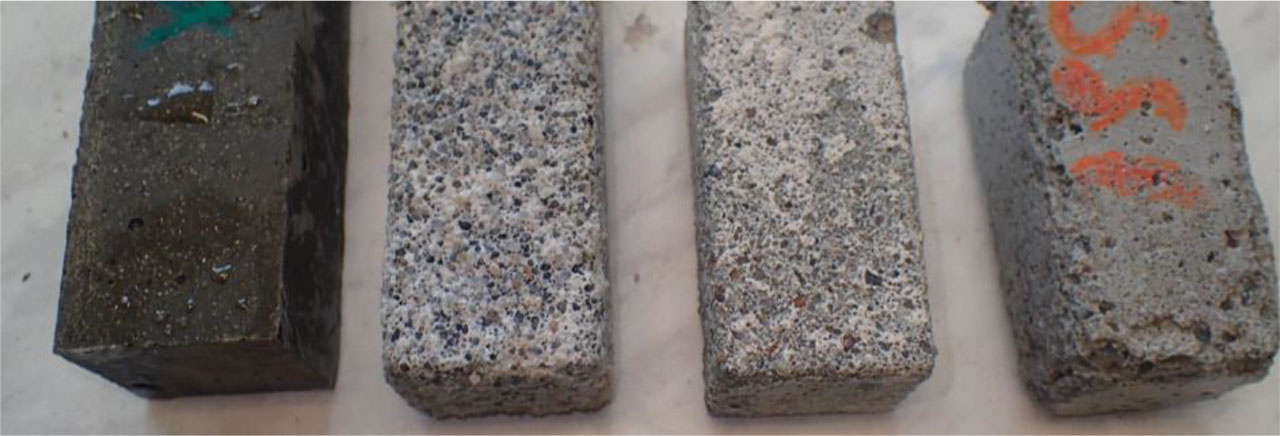
Figure 5:
Detail of beams stored in the laboratory (from left to right – EPX, SV, UHPC, and SSC) (Pesata, 2024)
Table 3:
Comparison of bending strength and compressive strength on test specimens (Pesata, 2024)
| Material Type | Reference compressive strength at 28 days | Strength in interspace after 6 months | Change in strength | |||
|---|---|---|---|---|---|---|
| Bending strength [MPa] | Compressive strength [MPa] | Bending strength [MPa] | Compressive strength [MPa] | Bending strength [%] | Compressive strength [%] | |
| SSC | 6.8 | 26.2 | 6.5 | 24.4 | −4.41 % | −6.87 % |
| SV | 12.5 | 63.1 | 11.2 | 56.4 | −16.80 % | −10.62 % |
| UHPC | 24.0 | 121.2 | 21.5 | 79.1 | −17.08 % | −34.74 % |
| EPX | 26.5 | 68.0 | 25.0 | 62.4 | −5.66 % | −8.24 % |
Comparison of bending strength showed a decrease of approximately 17% for both sulfate-resistant cement and UHPC-based screed. The other two materials—supersulfated cement and epoxy screed—demonstrated a reduction in bending strength of about 5%. Evaluation of compressive strength loss in chimney samples indicated that UHPC concrete experienced the greatest decline, reaching up to 35%. The remaining materials (epoxy concrete, supersulfated cement concrete, and sulfate-resistant cement concrete) exhibited compressive strength losses in a narrower range of 7% to 10%. These individual losses are also illustrated in the graph below (Figure 6) (Pesata, 2024).
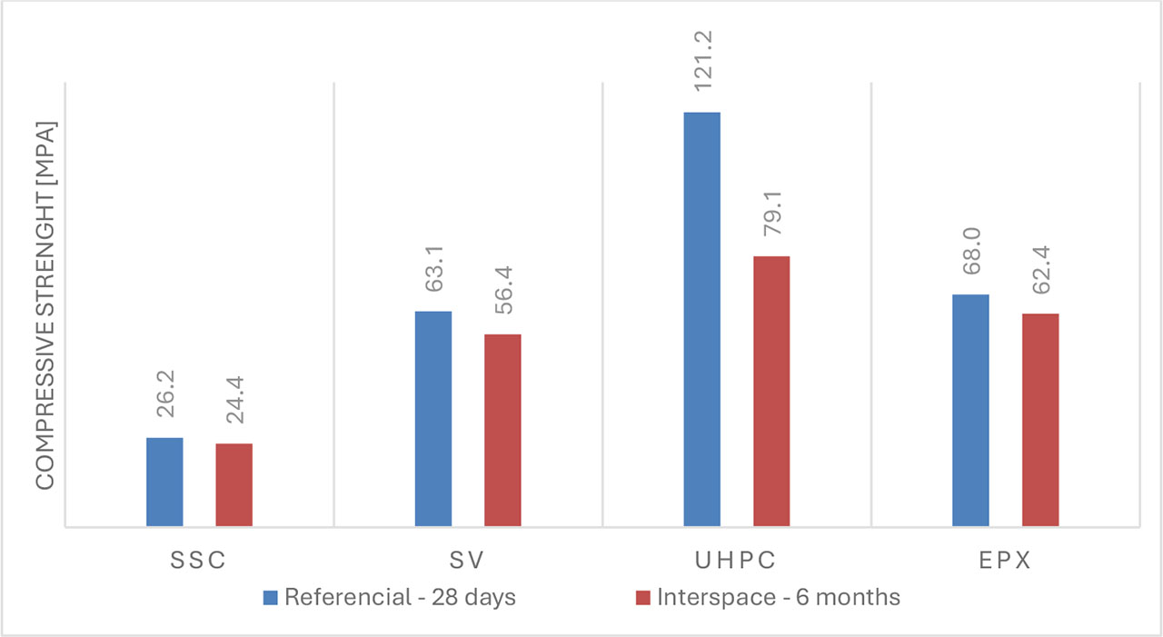
Figure 6:
Compressive strength reductions (Pesata, 2024)
4. Conclusion
Despite the application of modern protective systems, such as expansion compensators and acid-resistant fireclay linings, most industrial chimneys continue to experience some degree of condensation infiltration into their cavities. The construction technical survey results clearly highlight the extent of the resulting damage. The absence of a suitable protective layer has evidently accelerated both the severity and the progression of the degradation process.
The only material used in this study that showed minimum surface degradation was the epoxy mixture. All other materials exhibited surface degradation of approximately 1 to 2 mm over a 6-month testing period, both in the chimney cavity and laboratory environments. Considering the typical protective coating thickness of around 30 mm, the expected service life of these materials is estimated to be up to 10 years.
During testing of samples within the chimney cavity, the greatest reduction in compressive strength was observed in the UHPC concrete, with a decrease of approximately 35%. The remaining materials showed strength reductions of 10% or less. Samples based on epoxy concrete clearly demonstrated the best performance, exhibiting virtually no loss in strength.
Sulfuric acid is very destructive to concrete. Concrete is a basic material (it contains calcium hydroxide), while sulfuric acid is a strong acid. When they come into contact, an aggressive chemical reaction occurs, leading to gradual decomposition, erosion, and structural failure of the concrete. The inner surface of the chimney shaft and other structures in the interspace were not properly protected against the effects of aggressive substances until recently. In the event of the penetration of flue gases or condensate, important supporting elements are then degraded. The access to these structures is usually very complicated, which increases the cost of needed repair. For this reason, their protection should be a priority for the long-term function of the chimney as a whole.
Acknowledgements
This research and evaluation of experimental program were supported also by the project CirkArena, number CZ.10.03.01/00/22_003/0000045, supported by the European Just Transition Fund as part of the Operational Programme Just Transition under the aegis of the Ministry of the Environment of the Czech Republic.
Notes
[1] Contributed by Author Contributions
M.P. designed the study and the project. V.B. supervised the project. M.P. conducted the experiments and performed the data analysis. M.P., V.B. contributed to manuscript writing. O.S. Visualization manuscript and research project coordination. All authors critically reviewed and approved the final version of the manuscript and agreed to be accountable for all aspects of the work.
[2] Disclosure of Interest
The authors declare that they have no known competing financial interests or personal relationships that could have appeared to influence the work reported in this paper.
[3] Data Availability Statement
The data supporting the findings of this study are available from the corresponding author upon reasonable request and the datasets generated during and/or analysed during the current study are also available in the https://doi.org/10.5281/zenodo.18302413.