

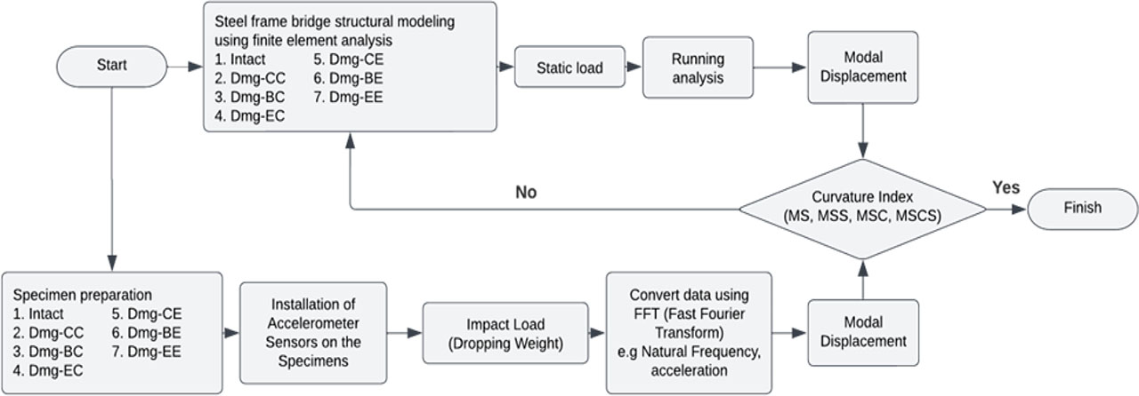
Figure 1:
General research flow

Figure 2:
Damage scenarios modelled in the experiment
Table 1:
Models and damage scenario
| Models | Damage scenario | Damage location |
|---|---|---|
| Intact | - | - |
| Dmg-CC | Cutting diagonal members | L/2 (0.5 L) |
| Dmg-BC | Buckling diagonal members | L/2 (0.5 L) |
| Dmg-EC | Missing diagonal members | L/2 (0.5 L) |
| Dmg-CE | Cutting diagonal members | L/5 (0.2 L) |
| Dmg-BE | Buckling diagonal members | L/5 (0.2 L) |
| Dmg-EE | Missing diagonal members | L/5 (0.2 L) |
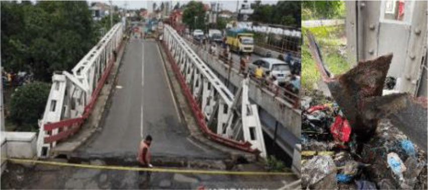
Figure 3:
Rembun Bridge after collapsing due to severe corrosion on the bottom chord (right)
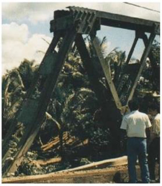
Figure 4:
The diagonal member at the end was struck by a vehicle
Table 2:
Section properties
| Members | Section properties [mm] |
|---|---|
| End post | L 30×30×3 |
| Upper chord | 2L 40×40×4 |
| Lower chord | 2L 40×40×4 |
| Diagonal members | L 30×30×3 |
| Portal strut | L 30×30×3 |
| Strut | L 30×30×3 |
| Girder | L 50×50×5 |
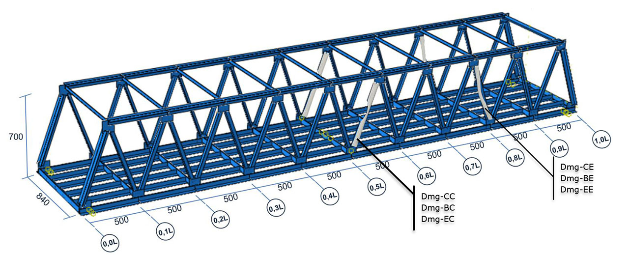
Figure 5:
Geometry of the steel frame bridge specimen

Figure 6:
The steel frame bridge specimen
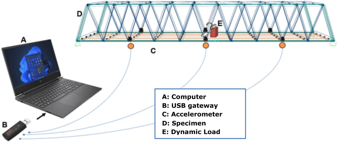
Figure 7:
General experimental setup
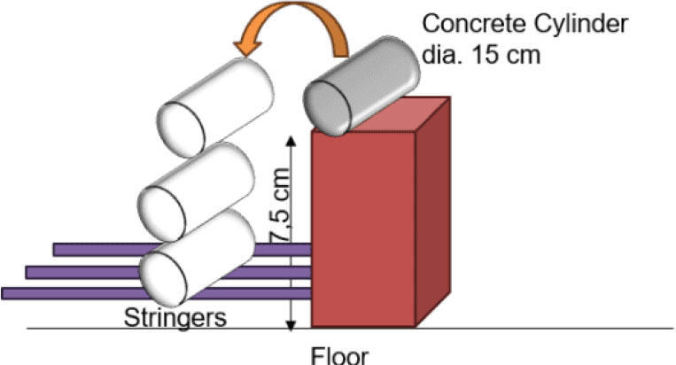
Figure 8:
Loading scheme
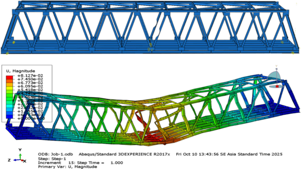
Figure 9:
Finite element model and modal displacement of the Dmg-CC structure
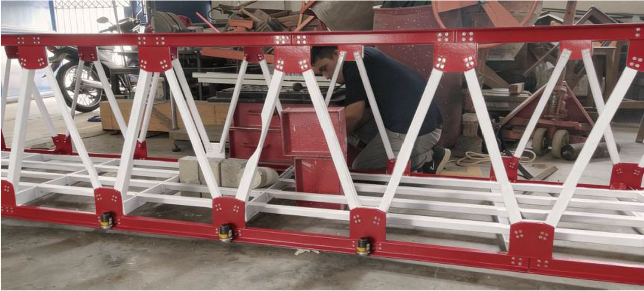
Figure 10:
Experimental simulation of mid-span diagonal member damage (Dmg-CC)
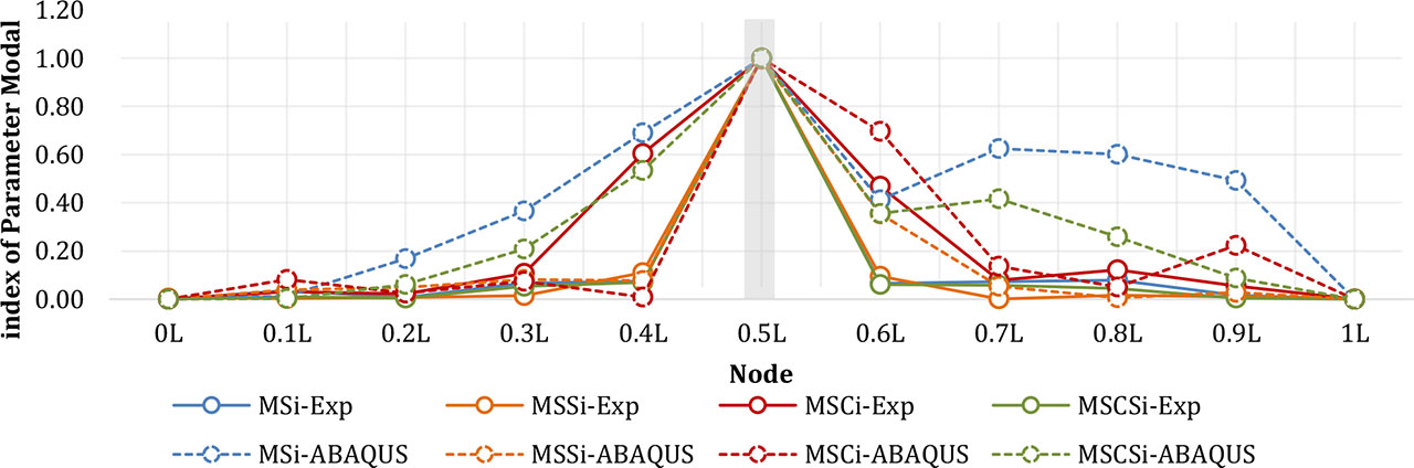
Figure 11:
Curvature index of each method on the DMG-CC model
Table 3:
Comparison of modal damage index accuracy for mid-span diagonal cutting damage (Dmg-CC)
| Modal parameter | Squared displacement difference (unitless) | SSE | MSE | RMSE | ||||||||||
|---|---|---|---|---|---|---|---|---|---|---|---|---|---|---|
| 0.0L | 0.1L | 0.2L | 0.3L | 0.4L | 0.5L | 0.6L | 0.7L | 0.8L | 0.9L | 1.0L | ||||
| MSIi | 0.00 | 0.00 | 0.03 | 0.09 | 0.38 | 0.02 | 0.12 | 0.30 | 0.27 | 0.23 | 0.00 | 1.44 | 0.13 | 0.36 |
| MSSi | 0.00 | 0.00 | 0.00 | 0.00 | 0.00 | 0.00 | 0.07 | 0.00 | 0.00 | 0.00 | 0.00 | 0.08 | 0.01 | 0.08 |
| MSCi | 0.00 | 0.00 | 0.00 | 0.00 | 0.36 | 0.00 | 0.05 | 0.02 | 0.01 | 0.03 | 0.00 | 0.48 | 0.04 | 0.21 |
| MSCSi | 0.00 | 0.00 | 0.00 | 0.02 | 0.22 | 0.02 | 0.09 | 0.13 | 0.05 | 0.01 | 0.00 | 0.53 | 0.05 | 0.22 |
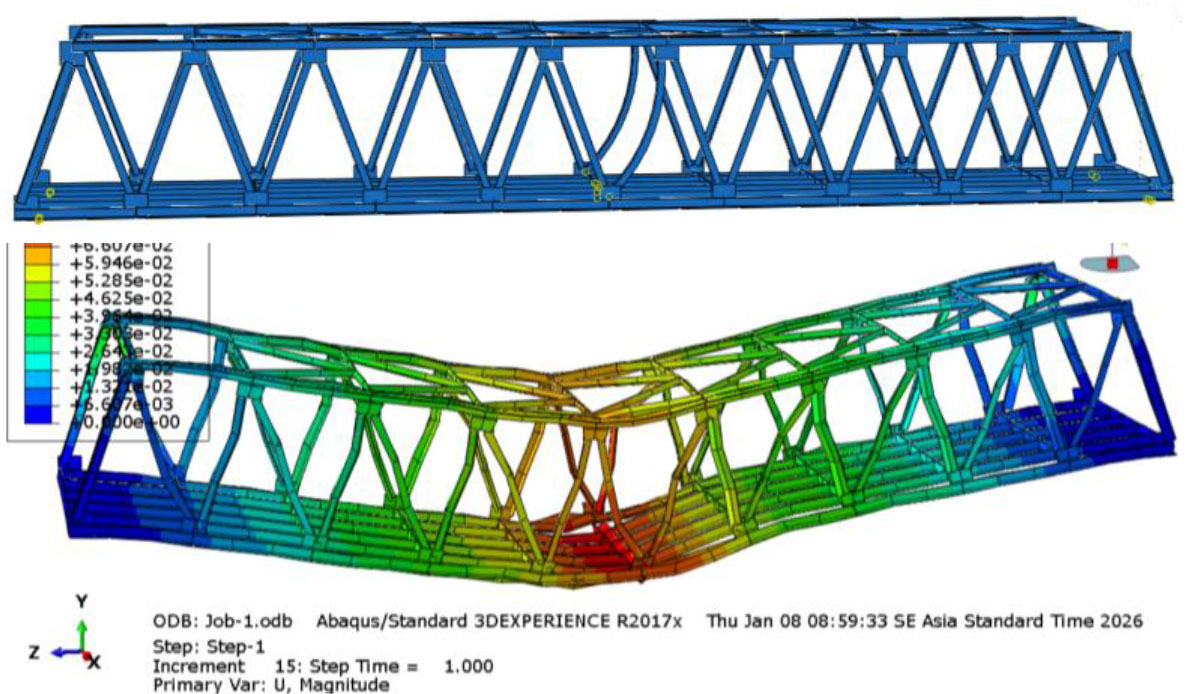
Figure 12:
Finite element model and modal displacement of the dmg-BC structure
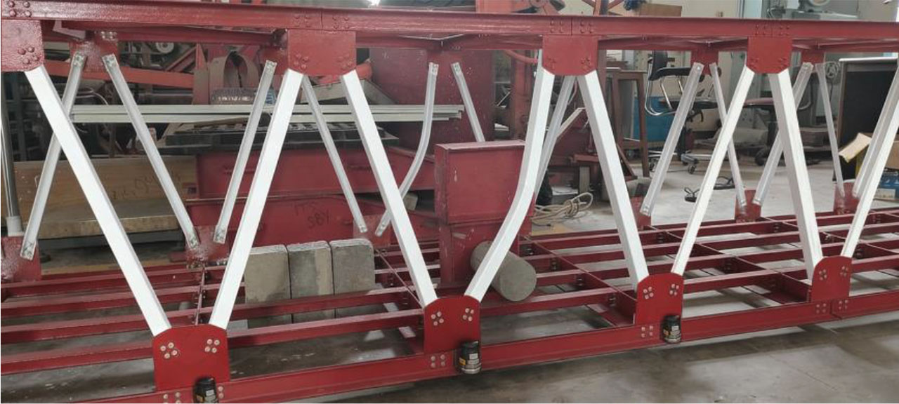
Figure 13:
Experimental simulation of mid-span diagonal member damage (Dmg-BC)
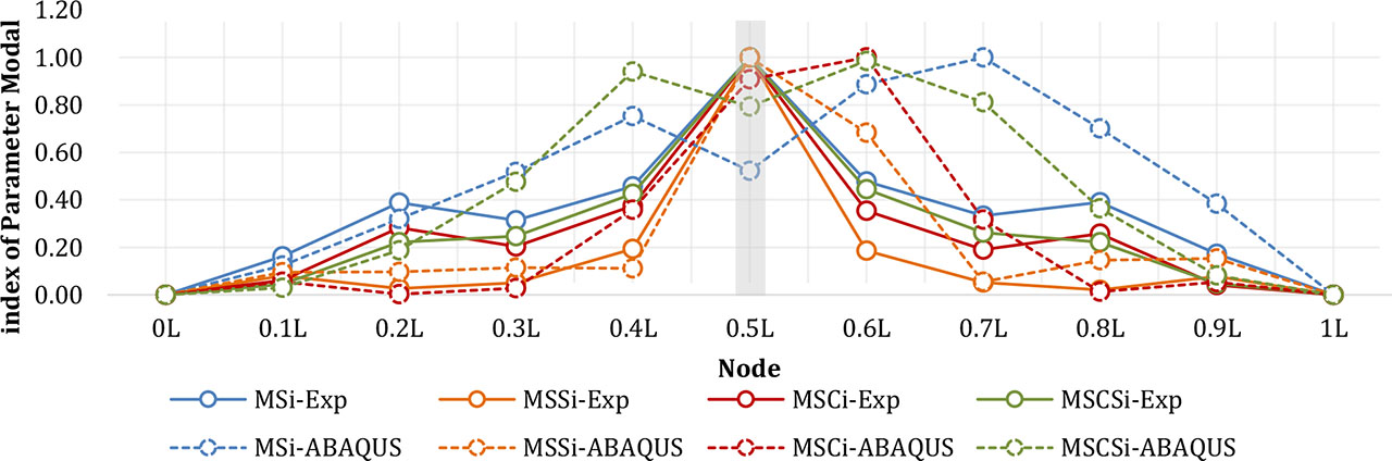
Figure 14:
Curvature index of each method on the DMG-BC model
Table 4:
Comparison of modal Damage Index Accuracy for Mid-Span Buckling Damage Model (Dmg-BC)
| Modal parameter | Squared displacement difference (unitless) | SSE | MSE | RMSE | ||||||||||
|---|---|---|---|---|---|---|---|---|---|---|---|---|---|---|
| 0.0L | 0.1L | 0.2L | 0.3L | 0.4L | 0.5L | 0.6L | 0.7L | 0.8L | 0.9L | 1.0L | ||||
| MSIi | 0.00 | 0.00 | 0.01 | 0.04 | 0.09 | 0.26 | 0.17 | 0.44 | 0.10 | 0.04 | 0.00 | 1.16 | 0.11 | 0.32 |
| MSSi | 0.00 | 0.00 | 0.00 | 0.01 | 0.01 | 0.00 | 0.25 | 0.00 | 0.02 | 0.01 | 0.00 | 0.29 | 0.03 | 0.16 |
| MSCi | 0.00 | 0.00 | 0.14 | 0.03 | 0.01 | 0.02 | 0.45 | 0.02 | 0.14 | 0.00 | 0.00 | 0.81 | 0.07 | 0.27 |
| MSCSi | 0.00 | 0.00 | 0.00 | 0.05 | 0.29 | 0.06 | 0.31 | 0.30 | 0.02 | 0.00 | 0.00 | 1.03 | 0.09 | 0.31 |
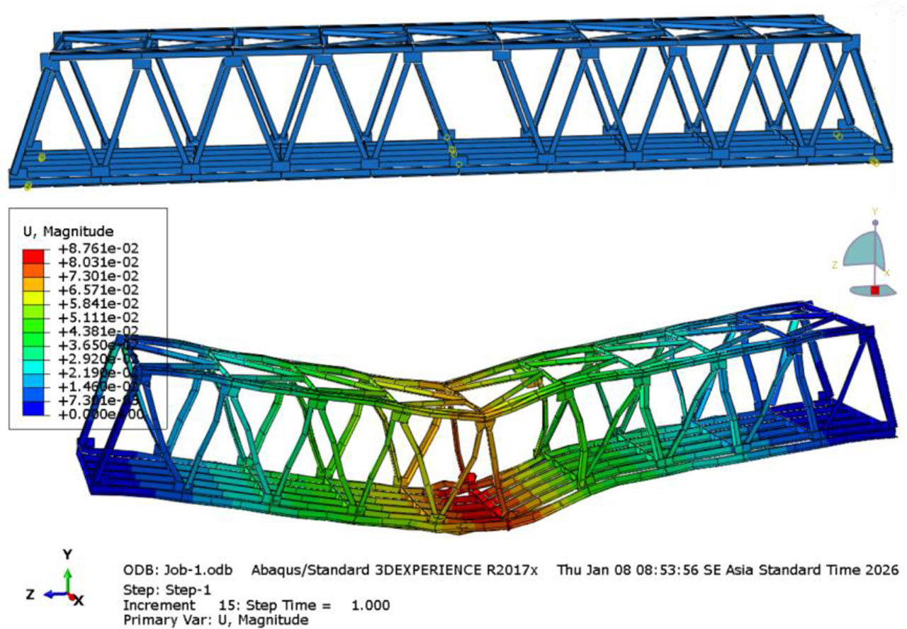
Figure 15:
Finite element model and modal displacement of the Dmg-EC structure
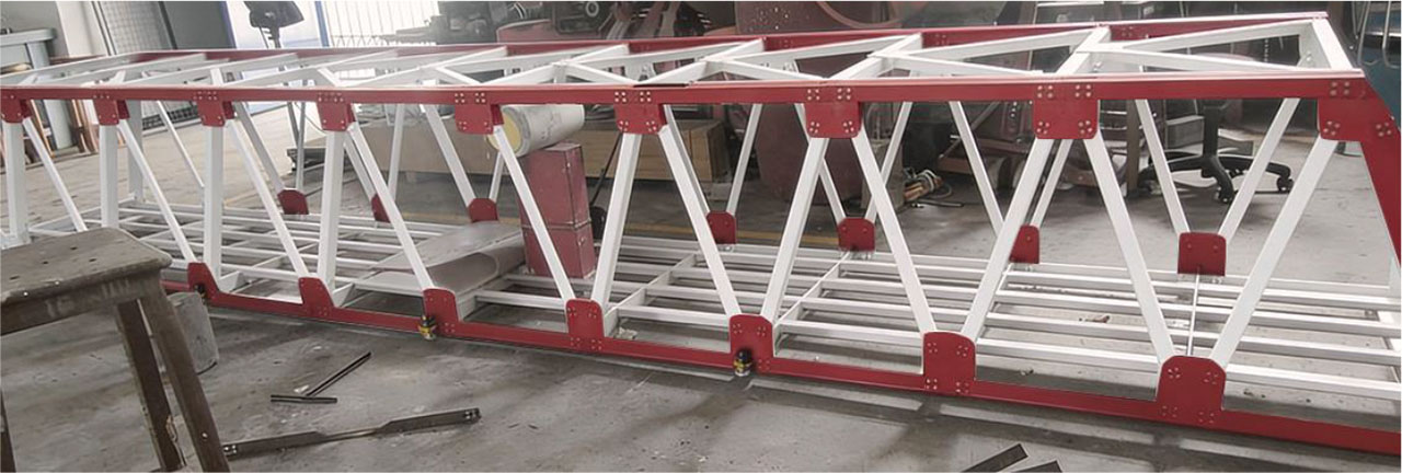
Figure 16:
Experimental simulation of mid-span diagonal member damage (Dmg-EC)
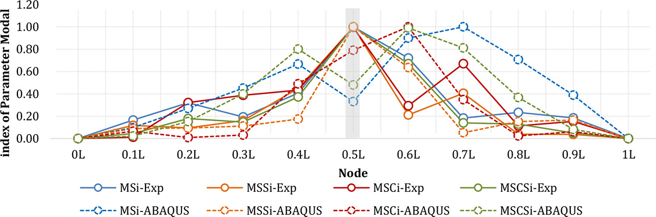
Figure 17:
Curvature index of each method on the DMG-EC model
Table 5:
Comparison of modal damage index accuracy for mid-span diagonal member removal (Dmg-EC)
| Modal parameter | Squared displacement difference (unitless) | SSE | MSE | RMSE | ||||||||||
|---|---|---|---|---|---|---|---|---|---|---|---|---|---|---|
| 0.0L | 0.1L | 0.2L | 0.3L | 0.4L | 0.5L | 0.6L | 0.7L | 0.8L | 0.9L | 1.0L | ||||
| MSIi | 0.00 | 0.00 | 0.00 | 0.07 | 0.07 | 0.55 | 0.03 | 0.67 | 0.22 | 0.04 | 0.00 | 1.66 | 0.15 | 0.39 |
| MSSi | 0.00 | 0.00 | 0.00 | 0.00 | 0.08 | 0.00 | 0.18 | 0.14 | 0.01 | 0.02 | 0.00 | 0.43 | 0.04 | 0.20 |
| MSCi | 0.00 | 0.00 | 0.12 | 0.13 | 0.00 | 0.11 | 0.50 | 0.15 | 0.03 | 0.01 | 0.00 | 1.06 | 0.10 | 0.31 |
| MSCSi | 0.00 | 0.00 | 0.00 | 0.00 | 0.18 | 0.39 | 0.11 | 0.45 | 0.06 | 0.00 | 0.00 | 1.25 | 0.11 | 0.34 |
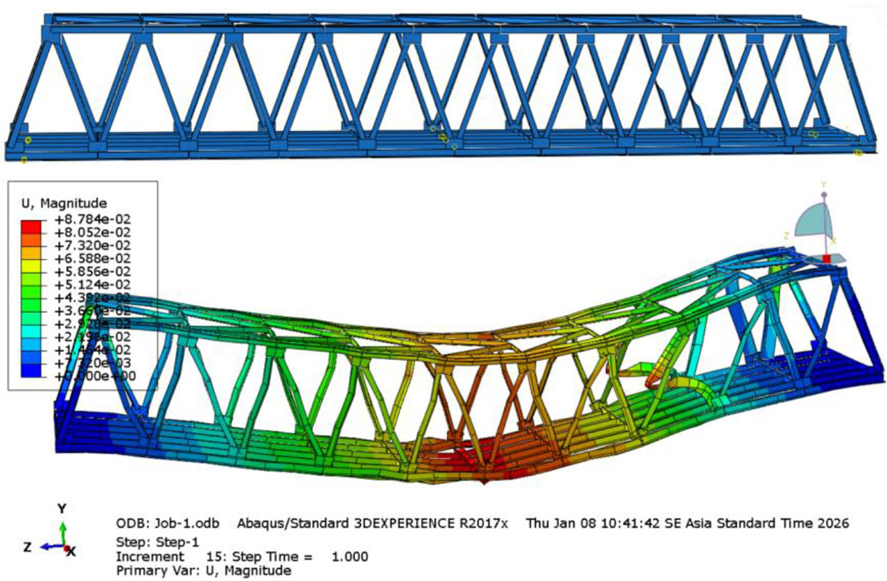
Figure 18:
Finite element model and modal displacement of the Dmg-CE structure
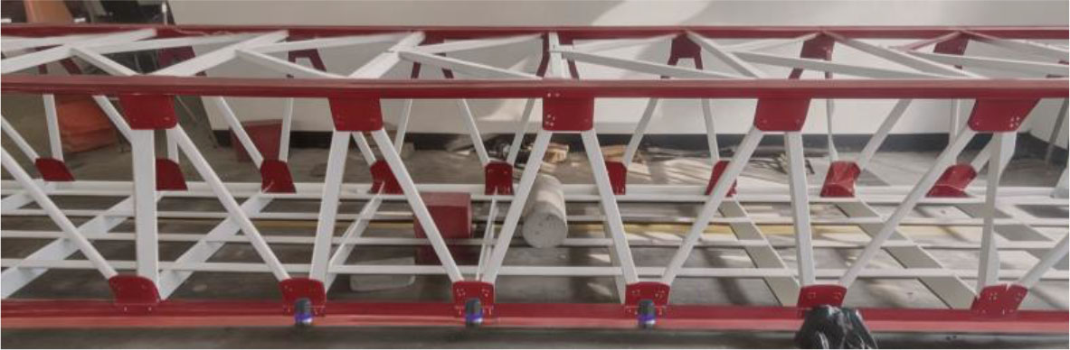
Figure 19:
Experimental simulation of diagonal member damage at 1/5 of the span (Dmg-CE)
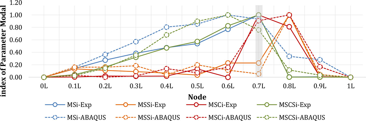
Figure 20:
Curvature index of each method on the DMG-CE model
Table 6:
Accuracy comparison of modal damage indices for 1/5-span diagonal cutting damage (Dmg-CE)
| Modal parameter | Squared displacement difference (unitless) | SSE | MSE | RMSE | ||||||||||
|---|---|---|---|---|---|---|---|---|---|---|---|---|---|---|
| 0.0L | 0.1L | 0.2L | 0.3L | 0.4L | 0.5L | 0.6L | 0.7L | 0.8L | 0.9L | 1.0L | ||||
| MSIi | 0.00 | 0.00 | 0.01 | 0.03 | 0.11 | 0.10 | 0.05 | 0.01 | 0.11 | 0.07 | 0.00 | 0.50 | 0.05 | 0.21 |
| MSSi | 0.00 | 0.00 | 0.00 | 0.01 | 0.00 | 0.05 | 0.01 | 0.03 | 0.00 | 0.00 | 0.00 | 0.11 | 0.01 | 0.10 |
| MSCi | 0.00 | 0.00 | 0.00 | 0.00 | 0.02 | 0.00 | 0.03 | 0.02 | 0.04 | 0.03 | 0.00 | 0.13 | 0.01 | 0.11 |
| MSCSi | 0.00 | 0.00 | 0.00 | 0.00 | 0.04 | 0.11 | 0.03 | 0.07 | 0.01 | 0.00 | 0.00 | 0.27 | 0.02 | 0.16 |
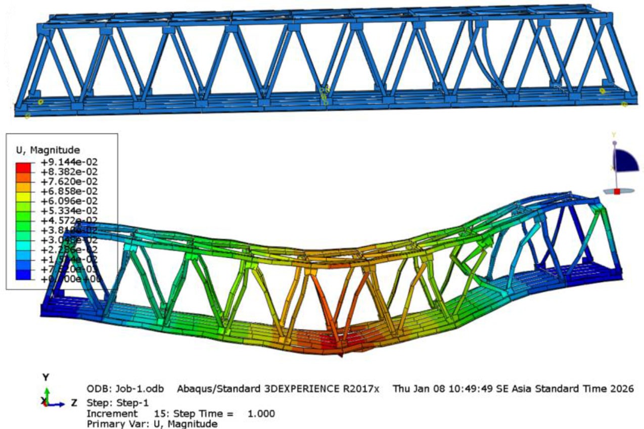
Figure 21:
Finite element model and modal displacement of the dmg-BE structure
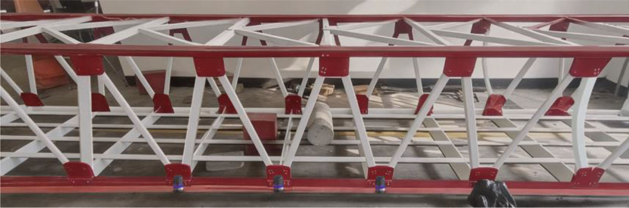
Figure 22:
Experimental simulation of diagonal member damage at 1/5 of the span (Dmg-BE)
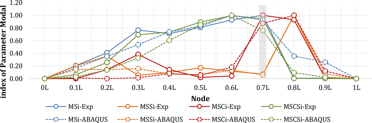
Figure 23:
Curvature index of each method on the DMG-BE model
Table 7:
Accuracy comparison of modal damage indices for 1/5-span diagonal buckling damage (Dmg-BE)
| Modal parameter | Squared displacement difference (unitless) | SSE | MSE | RMSE | ||||||||||
|---|---|---|---|---|---|---|---|---|---|---|---|---|---|---|
| 0.0L | 0.1L | 0.2L | 0.3L | 0.4L | 0.5L | 0.6L | 0.7L | 0.8L | 0.9L | 1.0L | ||||
| MSIi | 0.00 | 0.00 | 0.01 | 0.06 | 0.00 | 0.00 | 0.01 | 0.01 | 0.12 | 0.06 | 0.00 | 0.27 | 0.02 | 0.16 |
| MSSi | 0.00 | 0.01 | 0.05 | 0.01 | 0.00 | 0.01 | 0.00 | 0.00 | 0.00 | 0.01 | 0.00 | 0.08 | 0.01 | 0.09 |
| MSCi | 0.00 | 0.00 | 0.02 | 0.14 | 0.00 | 0.00 | 0.02 | 0.02 | 0.00 | 0.01 | 0.00 | 0.21 | 0.02 | 0.14 |
| MSCSi | 0.00 | 0.00 | 0.02 | 0.14 | 0.02 | 0.00 | 0.00 | 0.04 | 0.01 | 0.00 | 0.00 | 0.23 | 0.02 | 0.14 |
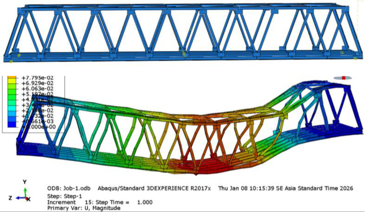
Figure 24:
Finite element model and modal displacement of the dmg-EE structure
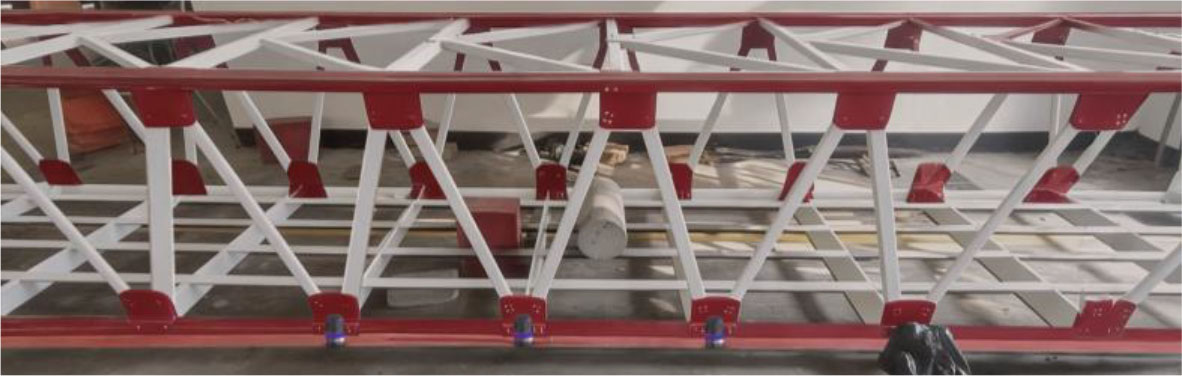
Figure 25:
Experimental simulation of diagonal member damage at 1/5 of the span (Dmg-EE)
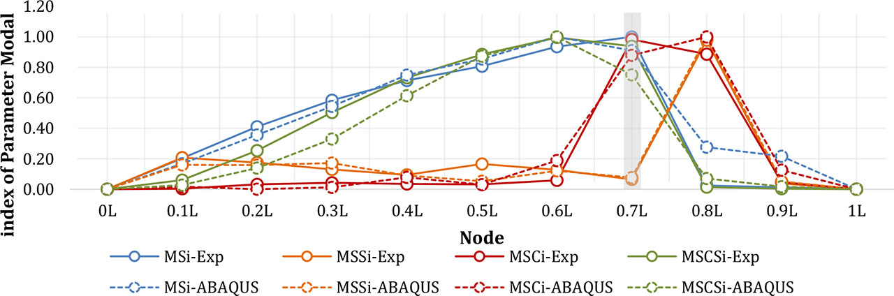
Figure 26:
Curvature index of each method on the DMG-EC model
Table 8:
Accuracy comparison of modal damage indices for 1/5-span diagonal member removal damage (Dmg-EE)
| Modal parameter | Squared displacement difference (unitless) | SSE | MSE | RMSE | ||||||||||
|---|---|---|---|---|---|---|---|---|---|---|---|---|---|---|
| 0.0L | 0.1L | 0.2L | 0.3L | 0.4L | 0.5L | 0.6L | 0.7L | 0.8L | 0.9L | 1.0L | ||||
| MSIi | 0.00 | 0.00 | 0.00 | 0.00 | 0.00 | 0.00 | 0.00 | 0.01 | 0.06 | 0.04 | 0.00 | 0.13 | 0.01 | 0.11 |
| MSSi | 0.00 | 0.00 | 0.00 | 0.00 | 0.00 | 0.01 | 0.00 | 0.00 | 0.00 | 0.00 | 0.00 | 0.02 | 0.00 | 0.04 |
| MSCi | 0.00 | 0.00 | 0.00 | 0.00 | 0.00 | 0.00 | 0.02 | 0.02 | 0.01 | 0.01 | 0.00 | 0.06 | 0.01 | 0.08 |
| MSCSi | 0.00 | 0.00 | 0.01 | 0.03 | 0.02 | 0.00 | 0.00 | 0.04 | 0.00 | 0.00 | 0.00 | 0.11 | 0.01 | 0.10 |