

1. Introduction
The RC columns are a major load-bearing structural element of the structure that support and distribute loads inside the structures (ALOBAIDI et al, 2025). Over time, these columns may necessitate repair or strengthening due to material deficiencies, errors in design, poor construction and quality control, increased loads, chemical and physical impacts, corrosion of steel reinforcement, fire risks, and insufficient maintenance (Ezz-Eldeen H., 2011). Therefore, maintaining the integrity of the columns is very important, because their collapse means the collapse of the whole structure (DEWI et al, 2024). Slender RC columns possess a mini cross-section relative to their height, leading to an increase in the bending moment due to the influence of the secondary moment. This makes the column more vulnerable to lateral deflection (Mohammed Za. et al., 2024). The slenderness ratio is a useful value for slender columns since a column’s slenderness often decreases its load-bearing capacity. Investigations into the slender RC columns have historically focused on their performance in relation to factors like slenderness ratios and cross-sectional dimensions, etc. (BAZANT et al., 1994; HYOG & JI-HYUN, 2010; CHUANG & KONG, 1995; AL-Najafi, 2016; Al-Sarraf et al., 2009).
Many researchers recently conducted research into how to strengthen slender RC columns. The steel jacket method has been used widely for strengthening columns. Specifically, those that are non-ductile. This technology has multiple benefits, such as decreased thickness compared to concrete jackets, lower weight, improved column confinement and load-bearing capacity, enhanced shear strength as well as lateral load resistance, increased ductility and stiffness, and decreased deflection (Abdel-Hay & Fawzy, 2015). To strengthen columns with steel jackets, the studies examined many variables, such as the bonding method and the size, shape, thickness, and length of the strengthening material.
Researchers (Dolce et al. 2003; Adam et al. 2009; Montuori & Piluso 2009; Campione 2013; Makki & Nimnim 2015) studied the influence of steel angles and battens on the structural integrity of short columns. The maximum load was noted to increase with bigger angles and batten size. Abdel-Hay & Fawzy (2015) studied experimentally the performance of short RC columns that were partially strengthened using steel angles and channel sections at the corners, specifically in the top and bottom thirds, while leaving the middle third unstrengthened. These sections were connected by straps and external ties, welded together, and anchored to the column with bolts. The findings demonstrated that increasing the total number of external ties enhanced the ultimate load capacity of strengthened columns. Furthermore, increasing the total number of steel straps applied with steel angles does not enhance the load capacity. However, their application with channel sections does increase the column load capacity. Additionally, increasing the jacket’s height (i.e., angle length) enhances its ductility and ultimate load capacity. Failure happens outside of the zone of strength. SEN DE., 2017 developed a research program to analyse the performance of steel-jacketed RC columns subjected to variations in load eccentricity through both experimental and analytical investigations. The findings of this investigation demonstrate that the steel angle and strip jacketing system has strong performance under both concentric and eccentric loading conditions. The capacity enhancement is approximately 240% with concentric loads compared to unstrengthened RC columns, but it is greater under eccentric loading than under concentric loading. However, as the slenderness ratio increases from 0 to 0.45 in this specific instance, eccentricity reduces the steel cage jacketed RC column’s ultimate capacity by roughly 15%. It further changes the ductility characteristics of jacketed RC columns. Moreover, the finite element analysis indicated that the mean ratio of experimental to numerical maximum load capacity was approximately 0.95, indicating a reasonable agreement with little overestimation. The existing analytical model can accurately predict the load-moment interaction curve of steel-jacketed RC columns with a substantial safety margin.
(Nimnim & Al-Bahadli, 2018) conducted an experimental and analytical examination of the structural capacity of slender RC columns that are strengthened with steel angles and battens, considering various factors such as the compressive strengths of concrete (normal and high), reinforcement ratios, batten spacing, and different levels of eccentricity. It was found that decreasing the eccentricity as well as batten spacing improved the ultimate load capacity of strengthened slender high-strength concrete columns. Additionally, because of the strengthening, the failure mode changes from sudden concrete crushing and localised longitudinal steel bar buckling to a gradual spalling of the concrete covering. They produced new analytical equations and noticed that the difference in maximum load between the proposed equations and experimental outcomes from this study and previous studies varied from 0.3% to 24.9%, having an average of 7.05% Eldeen et al. (2021) conducted a comprehensive assessment for strengthening methods of RC short columns using steel jackets. This study involved both experimental and analytical studies to determine the influence of characteristics like strip thickness and size, as well as spacing, angle size, and the strength of concrete, on bearing capacity, ductility, lateral capacity, and flexural strength. Researchers contrasted the findings of the experimental studies with design codes and analytical formulas proposed by others. The total enhancement in axial strength ranged from 18.65% to 109%, while the lateral strength experienced an increase from 63% to 68%. Strengthening RC columns with steel jackets is an efficient and reliable method for increasing their load-bearing capacity and overall strength. Yansiku et al., (2022) offer an external confinement method for strengthening slender circular reinforced concrete columns using steel sheet straps and applying an initial clamping force to the sheets. The steel sheet straps are fastened with bolts that produce differing initial clamp tensions. The proposed strengthening method, encompassing geometric and stress alterations, will improve the ductility of slender circular reinforced concrete columns under vertical and lateral pressures. The established analytical model accurately estimated the efficacy of the proposed clamp mechanism for use in practice. Abdelraheem et al. (2023) presented an experimental program of RC columns strengthened by steel angles as well as steel battens subjected to axial load. The principal research variables encompassed the influence of the aspect ratio (from the longer to the shorter side of the cross-section), as well as the distance of the steel battens and their size. The results indicate that the strengthening technique significantly improved the load-bearing capacity of the RC. This improvement was attributed to the restricting effect of the steel jacket and the capacity of the steel angles to support a significant portion of the imposed axial load. Buckling of the steel angles was the primary cause of failure for the majority of the strengthened samples. Salman & Al-Sherrawi (2024) presented a novel strategy utilizing an analytical model predicated on the plastic stress distribution method, aimed at developing an axial load-bending moment interaction diagram for a reinforced concrete column strengthened with steel battens and C-section jackets. The findings demonstrated that this strengthening method significantly enhanced the axial load and bending moment capabilities of the strengthened columns.
Based on the reviewed studies, it can be observed that previous research has extensively investigated the strengthening of RC columns using steel jackets, particularly for short columns and full-height strengthening schemes. These studies have consistently demonstrated improvements in load capacity, ductility, and stiffness. However, only limited attention has been given to slender RC columns, especially under eccentric loading conditions where second-order effects significantly influence structural behaviour. Furthermore, most available studies focus on full-length or near full-length strengthening, while the structural response and efficiency of partial-height strengthening in slender columns remain insufficiently explored. This gap highlights the need for experimental investigation into the effectiveness and limitations of localized strengthening techniques applied to slender RC columns subjected to eccentric loads.
Accordingly, the present study aims to experimentally investigate the behaviour of self-compacting RC slender columns partially strengthened with thin longitudinal and transverse steel plate strips placed at mid-height. The effect of different slenderness ratios under eccentric loading is examined to evaluate the efficiency, limitations, and failure characteristics of this low-cost strengthening technique.
2. Methodology
2.1. Research Design
The experimental program tests six slender rectangular RC columns which divided into two main categories. The first category consists of three RC columns made without strengthening, acting as control samples. The remaining three columns formed the second category, with strengthening placed at mid-height at a distance of 0.25 of the column’s length. Every column under investigation is made of self-compacting concrete with a compressive strength (f ʹc) of 23.22 MPa. The columns had slenderness ratios ranging from 22 to 31. These slenderness ratios were intentionally selected to represent practical ranges commonly encountered in reinforced concrete building columns. Although the numerical differences between the ratios appear limited, the experimental results demonstrate a clear and consistent influence of slenderness on load capacity, lateral displacement, and energy absorption behaviour. They were tested under eccentric loads with an eccentricity (ex) of 90 mm and an (hx) of 150 mm, giving a ratio (e/h) of 0.6. These factors were determined by preliminary study or reviews of the literature. The purpose of this experiment was to provide an accurate evaluation of the ultimate capacity and performance enhancement of RC slender columns when strengthened by steel jackets with variable slenderness ratios under eccentric loads. At the University of Technology, every mechanical property test has been carried out.
2.2. Specimens Description
The examined columns are categorized into two categories based on strengthening: one group with strengthening and another without. Each set of three columns has lengths of ℓu = 1.0 m, ℓu = 1.2 m, and ℓu = 1.4 m. There are three different relative slenderness ratios (ℓu/r): 22.22, 26.67, and 31.11. All columns had a rectangular cross-section of 200 × 150 mm with 20 mm clear concrete cover from all sides. The columns were reinforced with six bars of (Ø10) mm as longitudinal reinforcement, providing a steel ratio (ρg) of 1.42% [within the ACI 318M-19 Code requirements (2019) ranging from 1 to 8%], and (Ø6) mm bars spaced 75 mm apart acted as transverse reinforcement (ties). The laboratory test results showed that the longitudinal as well as tie reinforcing steel bars exhibited yield strengths (fy) of 523 MPa and 505.13 MPa, while the ultimate strengths (Fu) were 608 MPa and 560 MPa, respectively. Figure 1 (a) provides detailed information on the tested columns. According to the ACI 318M-19 guidelines (2019), the tested columns had corbels at both ends that allowed for the application of eccentric loading. To strengthen them, thin longitudinal with transverse steel plate strips, which are 0.5 mm thick and 30 mm wide, are placed at mid-height at 0.25 of the column’s length. The requisite laboratory tests showed that the steel plate’s yield strength (fy) was 221 MPa, and its ultimate strength (Fu) was 297 MPa. The strips are fastened with nails and epoxy (Sikadur, 31/41 CF Slow). Details of the strengthening are illustrated in Figure 1 (b and c).
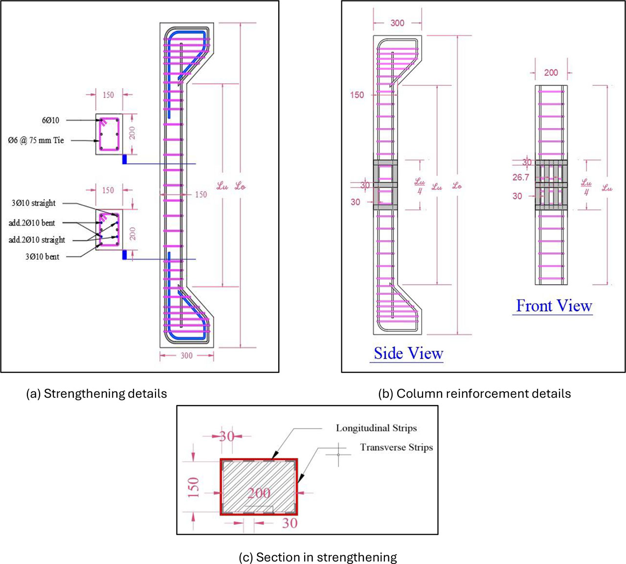
Figure 1:
Schema of column and strengthening details
2.3. Specimens Identification
The aim is to assess the column specimen by analysing many parameters, including its length, eccentric load, and strengthening as well as its slenderness ratio. Table 1 provides a description of the examined columns and indicates the main variables in the programme of experiments used in this study.
2.4. Concrete Mix Proportions
Self-compacting concrete (SCC) will be used for all columns. The properties of fresh concrete, including filling ability, viscosity, and passing ability, were assessed using slump flow, T500, V-Funnel, and L-Box tests, in accordance with ACI-237R (2007) and the provisions and guidelines of the European Federation of National Associations for Representing SCC (EFNARC-2002), as illustrated in Figure 2 The design mixture, which included 350 kg/m3 of cement, 800 kg/m3 of fine aggregate, 766.70 kg/m3 of coarse aggregate, 166.70 kg/m3 of limestone powder, and 154 L/m3 of water, was chosen after many mixed trials. The superplasticizer dosage (Sika ViscoCrete-180 GS) is 5.6 L/m3 (1.6% of the cement weight), with a water/powder ratio of 0.30 and a water/cement ratio of 0.44. The mix design was not altered so the grade of concrete was similar for every column and wasn’t considered as a variable. The monitoring was using control cylinders measuring 200 mm in length and 100 mm in diameter, which gave an average compressive strength (fʹc) of 23.22 MPa.
All column specimens were cast using the same concrete mix, and concrete strength was not considered a variable in this study.

Figure 2:
Fresh concrete tests
2.5. Casting and Preparation of Specimens
Each wooden mould was individually cast with a control specimen, and all columns were made in a horizontal orientation. The cages of steel reinforcement were inserted into the mould after the interior faces were cleaned and coated with oil. The 0.3 m3 falling rotary mixer was used to mix the concrete. Concrete mixing and casting are shown in Figure 3.
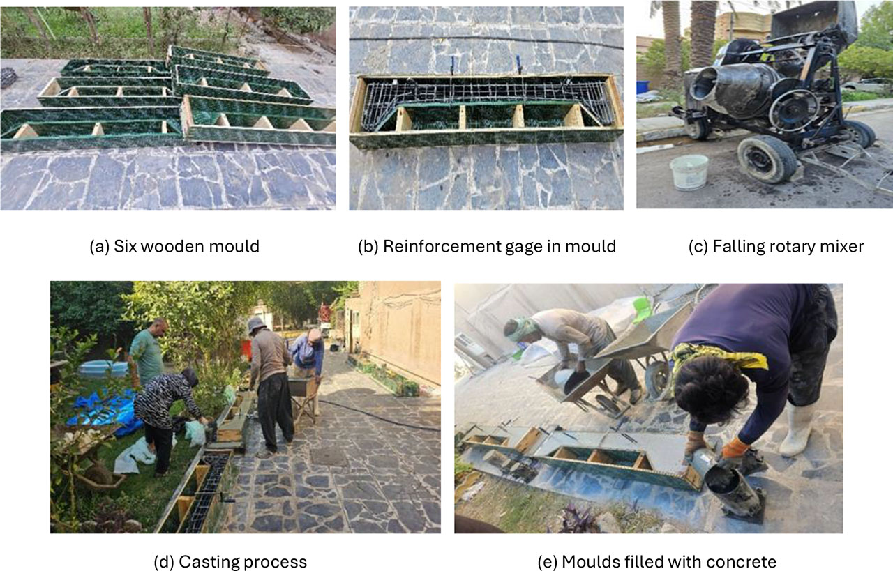
Figure 3:
Concrete mixing and Casting Process
After 28 days of curing, as seen in Figure 4, the concrete surface is prepared for strengthening by longitudinal and transverse thin steel plate strips. Corner warping, surface cleaning, and grinding are all steps in the process. The strips are fastened with nails and epoxy (Sikadur-31/41 CF Slow), as shown in Figure 5.

Figure 4:
Curing process

Figure 5:
Strengthening process and painting
2.6. Testing Process and Instrumentation
A hydraulic universal testing apparatus with a maximum load of 2500 kN was used for applying a monotonous load onto the specimens. The fabricated steel loading caps act as supports at both ends of the tested column. A wedge rod, placed in grooves at an eccentricity of 45 mm to the central point of the column cross-section, transfers the load to the loading cap. The upper and lower ends of the column have equal eccentricity, resulting in a uniform moment distribution along its length. This kind of support acts as the column ends’ hinged connection. A load cell was installed at the bottom of the apparatus during examination to document the applied load. The strain of columns is determined on both sides (compression and tension) in the centre of the height, and it is measured using foil electrical strain gauges on steel and concrete. As seen in Figure 6, the strain gauges are made by the Japanese company (TML), with models (PL-60-11-3LJC-F) for concrete and (FLAB-6-11-3LJC-F) for steel.

Figure 6:
Strain gage
In addition, two LVDTs were set up along the column’s height to measure the eccentric columns’ axial and lateral deflection. To evaluate lateral deflection, one device was installed at the midpoint of the column, while another was placed at the machine’s base to determine the shortening at any loading level along the column’s axial height. The data logger is connected to all this equipment, as seen in Figure 7 (a). The load-deflection response was measured while the load was gradually increased to failure. This procedure was repeated for each loading phase. Cracking observations were documented while applying additional safety measures. The crack pattern, load-bearing capacity, and mode of failure were carefully investigated. Figure 7 illustrates the testing procedure.
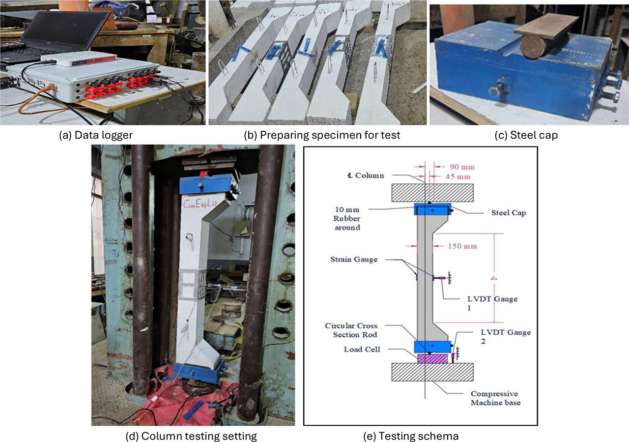
Figure 7:
Testing process and instrumentation
3. Results and Discussion
The test results, which include the maximum lateral displacement at mid-height, energy absorption capacity, and first crack and maximum load capacity, are shown for each column in Table 2.
Table 2:
Column specimens test results
| Groups | Col. No. | Column designation | First crack load | Ultimate load Pu [kN] | Lateral displacement ∆L @ Pu [mm] | Energy absorption [EA] [kN.mm] | *Energy absorption capacity [EAC] [kN.mm/mm] |
|---|---|---|---|---|---|---|---|
| Without strength | 1 | C0E90L1.0 | 106 | 152.96 | 13.53 | 1299.33 | 96.02 |
| 2 | C0E90L1.2 | 62 | 140.26 | 15.81 | 1284.09 | 81.20 | |
| 3 | C0E90L1.4 | 60 | 136.03 | 19.26 | 1534.29 | 79.65 | |
| With 0.25L strength | 4 | C0.25E90L1.0 | 115 | 178.06 | 12.47 | 1447.35 | 116.04 |
| 5 | C0.25E90L1.2 | 70 | 158.25 | 14.83 | 1455.01 | 98.10 | |
| 6 | C0.25E90L1.4 | 65 | 151.68 | 18.606 | 1733.00 | 93.14 |
3.1. Ultimate Load Capacity and Lateral Mid-Displacement
RC slender columns exhibit an enhancement in both ultimate load capacity and lateral mid-displacement when strengthened by steel plate strips located at 0.25 of the column’s length in mid-height, as evidenced by the results shown in Table 2. Whether the column is strengthened or not, with eccentric loading, the maximum loads (Pu) decrease while the lateral mid-displacement rises as the slenderness ratio (column length) increases. This effect results from the eccentricity inducing a secondary bending moment over the column section in addition to the axial compressive stress. Figure 8 illustrates that strengthening of columns enhances lateral mid-displacement and maximum load capacity. The lateral displacement reduction and load capacity increase by 7.83% and 16.41%, respectively, with a slenderness ratio of 22.22. Furthermore, at a slenderness ratio of 26.67, the increments are 12.83% and 6.21%, and at a slenderness ratio of 31.11, the increments are 11.50% and 3.41%. This improvement results from the strengthening’s effectiveness, which prevents the lateral deflection and will lower the column cross-section’s secondary bending moment.
Figure 9 shows the assessment of all columns against the reference column, which possesses the lowest load capacity. The maximum load of C0.25E90L1.0 (column with strengthening) was enhanced by 30.90% relative to C0E90L1.0 (column without strengthening), which improved by 12.45%. This graphic illustrates the effect of reinforcement on improving the maximum capacity for load of columns with differing slenderness ratios subjected to eccentric loads.
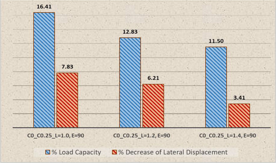
Figure 8:
Ratio of tested unstrengthen and strengthened columns for load capacity and decrease of lateral displacement (%)
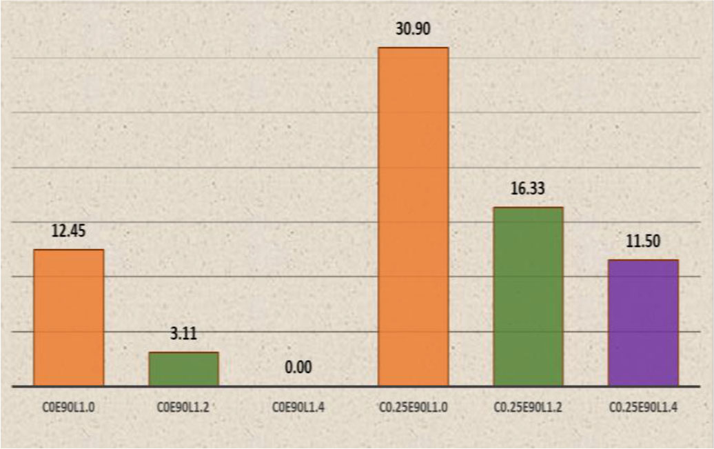
Figure 9:
Ratio of tested columns capacity to the weaker column C0E90L1.4 %, (Pcolumn / PC0E90L1.4 ×100 – 100)
Figure 10 depicts the comparison of all columns against the reference column, which exhibits the maximum displacement. The strengthened column, C0.25E90L1.0, had a 35.24% improvement in lateral displacement reduction, while the unstrengthened column, C0E90L1.0, had a 29.74% increase. This figure shows how strengthening improves the lateral deflection of columns under eccentric loads via various slenderness ratios. As shown in Figure 11, the load-lateral deflection curve shows how strengthening increases the stiffness of the column by decreasing displacement as the maximum load increases.
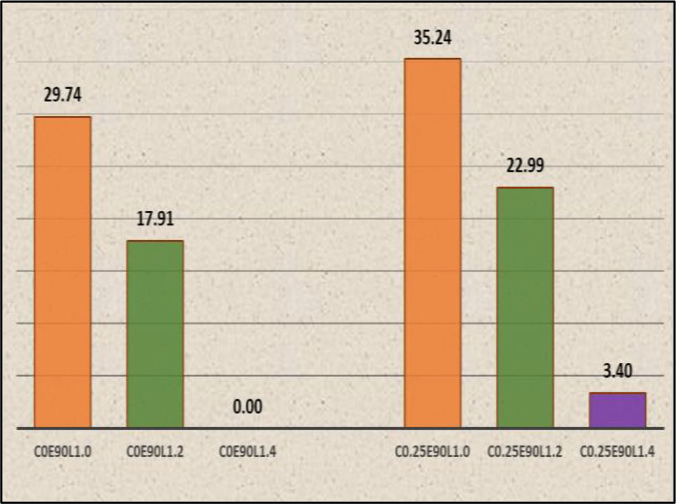
Figure 10:
Decrease ratio of lateral displacement for tested columns to the ultimate displacement of column C0E90L1.4 (%)
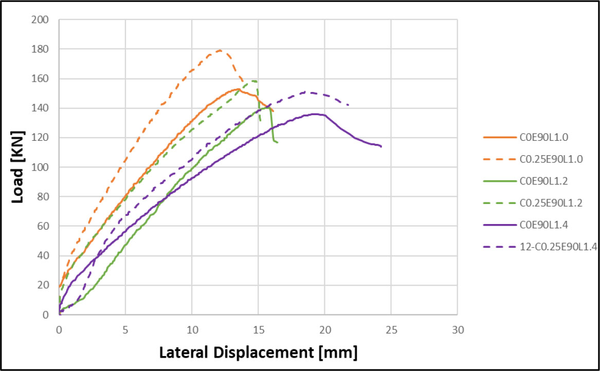
Figure 11:
Load-lateral displacement curve at mid-height of tested columns
3.2. Results of Strain
Figure 12 illustrates the contrast between strengthened and unstrengthened columns. It indicates that the strengthening significantly reduces the strain on the compression and tension sides of strengthened columns, resulting in reduced cracking. Strengthened columns also show linearity on both the tension and compression sides.
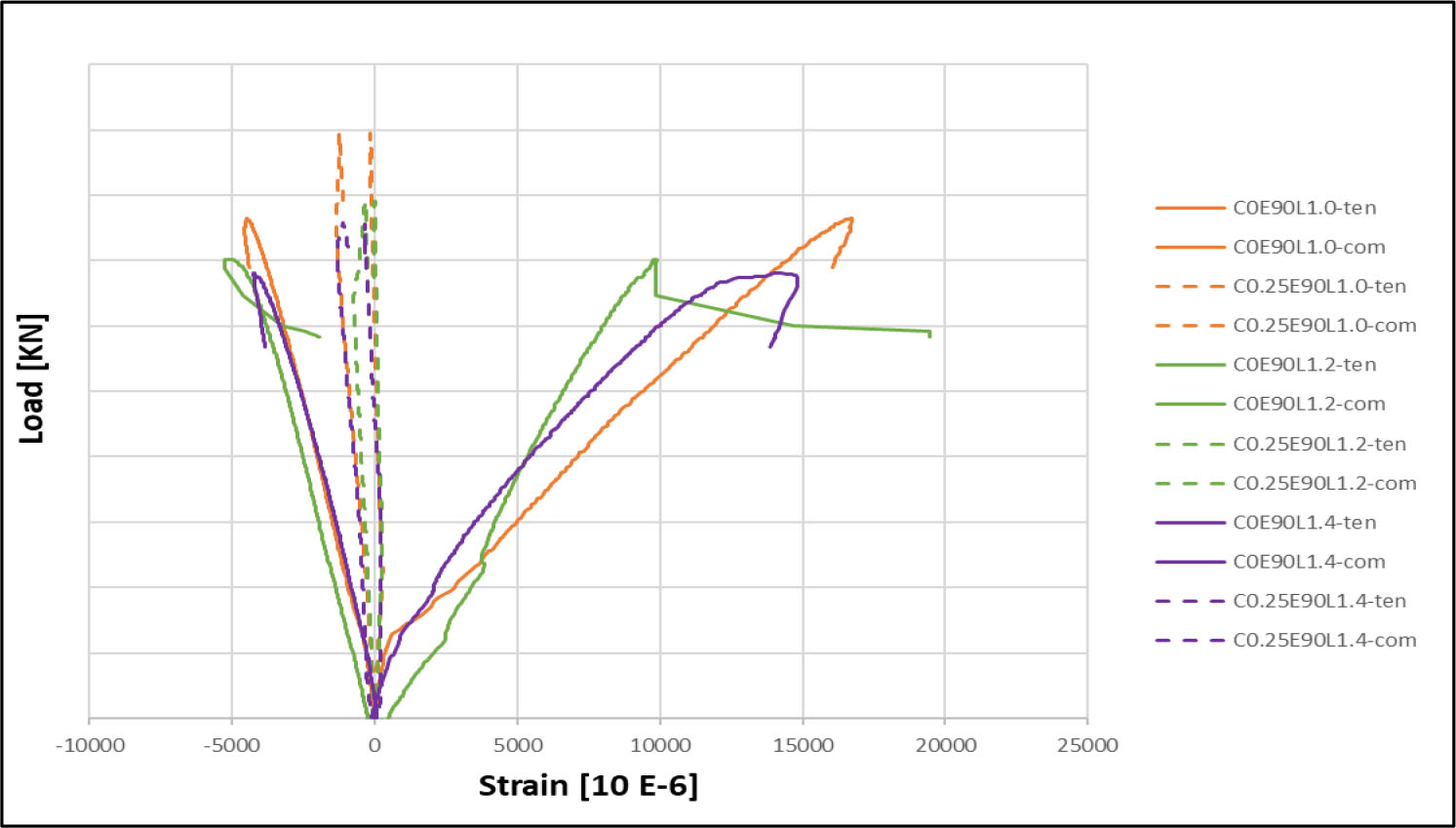
Figure 12:
Load-strain curve at mid-height of Tested columns
Although eccentric loading induces bending moments that may generate tensile stresses locally, the applied axial load level in slender columns was sufficiently high to shift the neutral axis outside the cross-section. As a result, compressive strains were recorded on both monitored faces at mid-height. This behaviour is typical in slender columns dominated by axial compression combined with second-order effects, where global instability governs the response rather than pure flexural behaviour.
3.3. Energy Absorption
The energy absorption capacity offers critical information regarding the performance of RC slender columns under lateral loads. An enhanced energy absorption capacity indicates increased flexibility and the ability to withstand dynamic loads. This knowledge is crucial for structural design, especially in regions subjected to earthquakes or others lateral stresses; thus, it enhances the stability and durability of constructions. Therefore, evaluating the energy absorption as well as the dissipation capacity of RC slender columns is important when analysing their behaviour (Lu, & Yu, 2003). “Energy Absorption” or “Dissipated Energy” is the scientific term for the region below the load with a lateral displacement curve. The column calculates the energy before reaching the maximum deflection. A normalized measurement of "Energy Absorption Capacity" can be computed by dividing the dissipated energy (energy absorption) by the maximum lateral deflection (Lu, & Yu, 2003). Table 2 and Figure 13 show the enhancement in energy absorption capacity resulting from the strengthening of the column. Figure 14 shows the enhancement rates of strengthened columns with slenderness ratios of 22.22 (1 m), 26.67 (1.2 m), and 31.11 (1.4 m) are 20.85%, 20.81%, and 16.93%, respectively. The strengthening technique decreased lateral displacement while concurrently raising the maximum load, hence enhancing the column’s stiffness as well as energy absorption capacity.
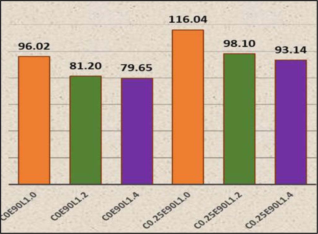
Figure 13:
Energy absorption capacity for all tested columns [kN.mm/mm]
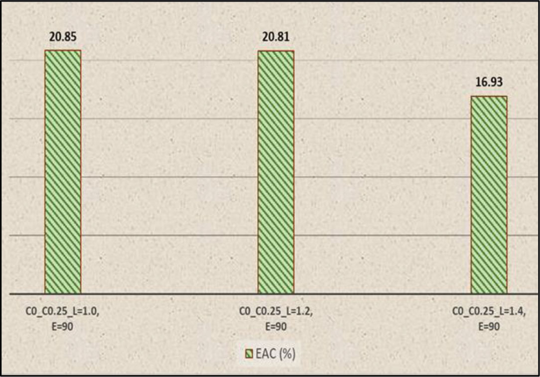
Figure14:
Ratio of tested unstrengthen and strengthened columns for energy absorption capacity (%)
3.4. Failure Mode and General Behaviour
Generally, during the initial loading phases, no visible cracks were observed in the columns. As the load progressively increased from first application to failure, cracks resulting from tension and compression could be observed and recorded. Tension cracks initially formed via the application of an eccentric load. When the applied load develops, cracks on the column’s exterior face (tension face) start to appear and become large in size and number along its height, eventually causing the column to fail. When unstrengthened columns fail, as seen in Figure 15 (a to c), the number of cracks on the tensile face increases noticeably along the column height. Crack propagation happens in the middle third, resulting in the crushing and spalling of the concrete on its compressive face. Furthermore, buckling was most commonly observed due to eccentricity. It should be noted that the strain measurements represent local responses at mid-height, while the observed cracking patterns and failure modes are governed by the global instability behaviour of the slender columns. Tensile cracking and buckling may develop in regions affected by second-order deformation and lateral displacement, even if compressive strains are recorded locally. Therefore, the failure mechanism is controlled by overall column instability rather than the strain state at a single cross-section. Figure 15 (d to f) show the failure of strengthened columns. This shows a notable reduction in the number of cracks, and the failure position shifts either up or down in the strengthened part. This situation happens due to the transmission of stresses from the strong part to the weak part.
In conclusion, the column failed as a result of deep, wide cracks and high compressive stresses brought on by the significant lateral displacement produced by a continual application of the eccentric load. Slender columns fail due to instability issues rather than a lack of strength (Hassanein, 2014). The stresses transfer from the stronger section to the weaker section when slender columns are strengthened with steel plate strips that cover 0.25 of their length and are subjected to eccentric loads. This delays failure and shifts its location while increasing its load capacity.
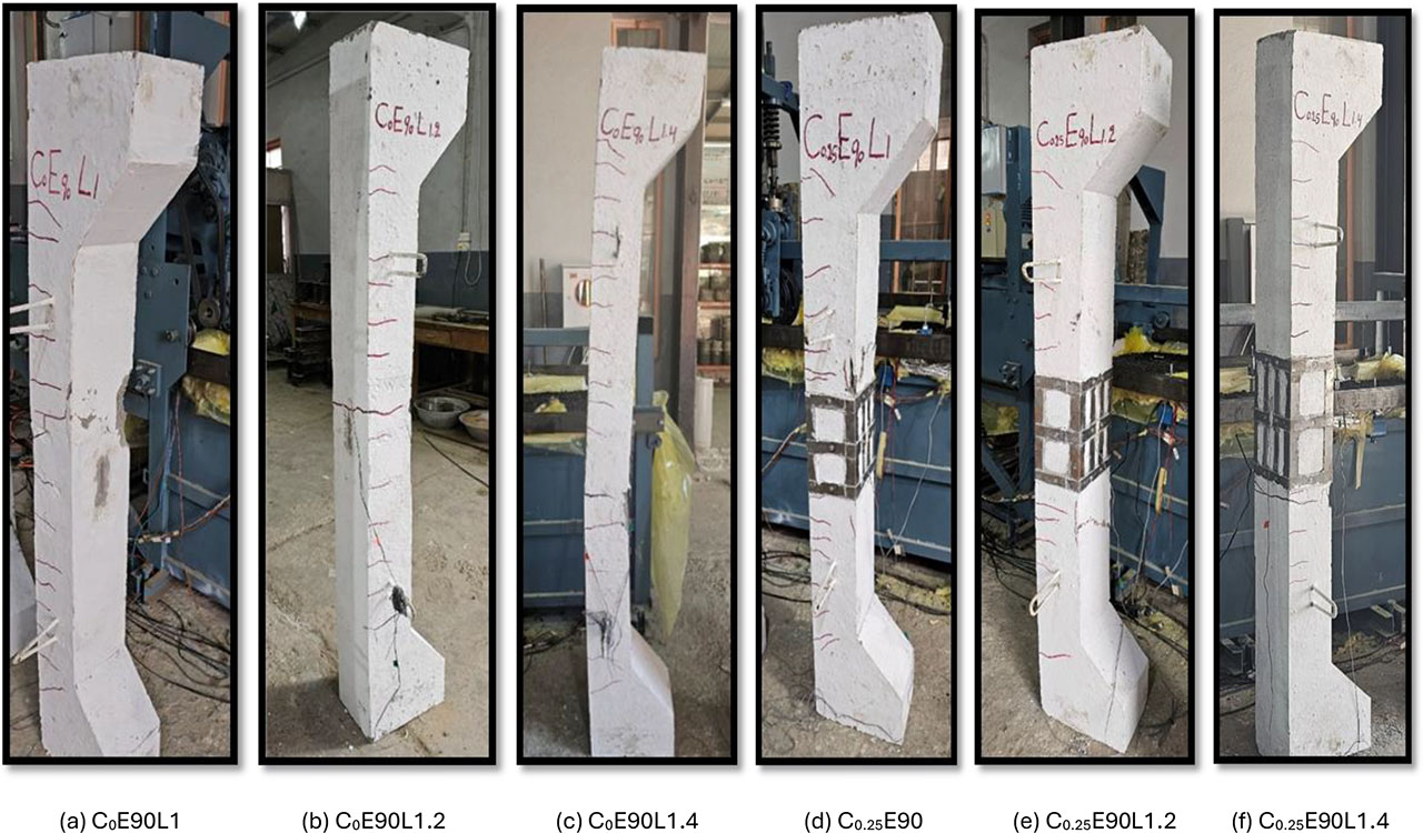
Figure 15:
Columns failure
4. Conclusion
The research offers a significant benefit by presenting a method that works as a practical and cost-effective alternative for strengthening slender RC columns, thus providing a reliable and safe choice for structural engineers. The experimental results involving strengthening of self-compacting RC slender columns with longitudinal as well as transverse thin steel plate strips (0.5 mm thick) installed at 0.25 of the column’s length at mid-height, at different slenderness ratios under eccentric loading, provide the following conclusions:
The slenderness ratio significantly affects the lateral displacement and load-bearing capacity of columns, both strengthened and unstrengthened; as the slenderness ratio increases, lateral displacement increases while load capacity decreases due to eccentricity creating a secondary bending moment.
The load capacity of the RC slender column is increased when it is strengthened, as compared to reference columns that are not strengthened with different slenderness ratios.
The strengthening contributes to the reduction in lateral displacement, which becomes noticeable as the slenderness ratio rises.
The confinement of the strengthening results in a stiffer column by reducing the secondary moment, improving load-bearing capacity, and reducing lateral displacement.
Strengthening increase the energy absorption capacity of columns, considerably enhancing the safety and durability of a structure, especially in regions subject to earthquakes.
The strengthening altered the stress distribution along the column height, resulting in a shift of the failure location outside the strengthened zone. This observation indicates that the selected strengthening length (0.25L), while effective in delaying failure, may be insufficient to fully control instability in highly slender columns.
5. Recommendations
The authors would like to recommend the following:
Study the deference cross-section of slender columns such as circular.
Use the same technique to strengthen the entire length of the slender column instead of just 0.25 of its length.
Extend the scope of the research by using different types of loads, including increased eccentricities and cyclic loads.
Notes
[2] Contributed by Author Contributions
B.R. designed the study and supervised the project. A.S. conducted the experiments, contributed to manuscript writing. A.S. and B.R. performed the data analysis. All authors critically reviewed and approved the final version of the manuscript and agreed to be accountable for all aspects of the work.