

1. Introduction
Stepped spillways were used extensively in hydraulic engineering energy absorption facilities and had much promise since they can dissipate energy more quickly whilst spilling more floodwater (Chanson, 2015). They may lessen the amount of downstream river erosion and the quantity of downstream durability and safety, which have outstanding technical and economic performance measures (Felder et al, 2012). Numerous research was carried out to optimize the layouts to enhance the stepped spillway's energy absorption impact and hydraulic characteristics. Stepped spillway is indeed not limited to having flat, even steps; other stepped chute models were developed with varying channel slopes (Ashoor & Riazi, 2019), non-uniform steps (Felder & Chanson, 2012), and pooling steps (Felder & Chanson, 2013). The energy absorption efficacy of pooled stepped spillways was conducted well. However, unsteady free surface variations happened at a chute slope of 8.9°, which could potentially cause issues for step structure, according to (Felder & Chanson, 2013; Mohammed, 2025). physical experimental studies on pooled stepped spillways with chute inclines of = 8.9°, 14.6°, and 26.8°. Additionally, a novel sort of pooled stepped spillway with pool on every other step's horizontal side was suggested, and several researchers have studied its flow properties. (Felder & Chanson, 2013; Scheres et al, 2020; Hunt et al, 2022).
The relevant step spillway variables from various experimental investigations that were carried out to investigate flow regime of pooling stepped spillways. Findings show that interval-enclosed spillway may entrain more air and lower danger of cavitation. (Kökpinar, 2004) compared air-liquid flow characteristics for 30° interval-stepped spillway with traditional stepping stepped spillway, and a pooling stepped spillway. After conducting physical tests on interval-stepped spillways with θ= 30° and 18.6°. (Ahmed, et al., 2024) discovered that these spillways achieved a high degree of energy dissipation when the pool elevation was known. Experiments were performed by (Felder & Chanson, 2013) on an interval-stepped spillway with a modest angle (θ =8.9°). Their situations have been evaluated in transition and nappe flow regimes; however, the discharge and chute angle prevented them from achieving a skimming flow. All studies above concluded that interval-stepped spillways have completely different hydraulic properties from pooling step spillways and flat stepped spillways; their energy absorption feature still seems weak, and a thorough investigation is required.
Dealing baffle blocks with graded spillways is usually preferable to disperse more energy (Chanson, 2002). To dissipate energy when water is released via gates or the spillway crest, hydraulic jump construction in stilling basin is typically used. Baffle blocks were a kind of structural blockage arrangement that enabled financial gains by reducing the size of the stilling basin and creating advantageous flow patterns (Al-Naely, & Khassaf, 2019; Al-Naely, & Khassaf, 2019). In order to disperse more energy and lower size of stilling basin, several authors have concentrated on baffle blocks that use tiered spillways. According to (Rageh, 1999) method on “Impact of Baffle Blocks on the Behaviour of Hydraulic Jump,” these baffle blocks may effectively shorten hydraulic jumps. (Frizell & Svoboda, 2012) attempt to demonstrate super cavitation high energy dissipation than ordinary block in their article Performance of Type 3 Stilling Basins - Stepped Spillway Investigations. According to several experts that studied the hydraulic features of energy and flow dissipation across stepped spillways, stepped spillways dissipate more energy than smooth or conventional ones, and the amount of energy dissipation decreases as the number of steps increases. In their article “Dissipation of Hydraulic Energy by Curved Baffle Blocks,” researchers of various baffle block designs proposed that their research had revealed that curved baffle blocks dissipate more energy than standard ones. (Gouri & Balkrishna, 2024) compare curved baffle blocks to the standard ones with a trapezoidal shape, concluding that curved baffle blocks do so.
(Habibzadeh, 2013) worked on an "Exploratory Investigation of Submerged Hydraulic Jumps with Baffle Blocks" to demonstrate the use of baffle blocks underwater. The results of preliminary investigation on submerged leaps with baffle walls and blocks downstream of spillway were compared to values for free jumps with and without baffle blocks in terms of max energy absorption efficiency. It is discovered that at significant submergences, energy loss must be lower without the baffle blocks than with a free leap. According to (Chanson, 1994) stepped spillways seem to be a typical hydraulic structure utilized as both a low-head hydraulic construction and to safely release water in the event of a flood. Air-water fluxes downstream of the flow seem to be intricate, and a variety of three-dimensional phenomena occur, such as high momentum exchanges between distinct flow zones and interaction between the free surface and flow.
(Gandhi & Singh, 2016; Gandhi, 2014; Gandhi, 2014; Gandhi & Singh, 2014; Sumit & Vishal, 2013) experimental investigation on the variance of flow behaviour for suddenly continuing to expand channels with different expansion ratios was done to understand the relationship between subsequent depth proportion better, jump height, jump efficacy, relative jump length, roller length, and other variables under various flow rates. The third variable also considers dimensions of baffle blocks and end sill. In order to represent characteristics for greater flow velocity (Froude number) ranging from 2 to 9, a dimensionless technique has been used. Reynold's number, which the findings of other researchers can support, had also been studied in this work to demonstrate the influence of boundary layer thickness. Prismatic (U-shaped, trapezoidal, and rectangular) and non-prismatic (suddenly expanding) channels are considered while studying undular hydraulically leap in turbulent open channel flow. On the gathered experimental data set for 12 distinct hydraulic jump properties with and without baffle blocks and sills, principal component analysis (PCA)/factor assessment (FA) is used. The main objective was determining the most important factor affecting the hydraulic jump. The findings have been validated and reported regarding shared primary jump properties. In a couple of his studies, the researcher also provided substantial weightage to the function of sediment in high-velocity flows to explain the effects of shear stress on a uniform and non-uniform sediments.
In order to determine the limiting design requirements in extending channels, (Rageh, 1999). researched and examined the impact of a baffle block on a radial hydraulic jump. An investigation with a Froude number range of 2 to 6.5 was conducted in a lab. A leap in a stilling basin with diverging sides is referred to as a "radial hydraulic jump." The radial hydraulic leap has a little larger energy loss than the equivalent rectangular jump. The exploration of radial hydraulic jump on a horizontal slope with influencing baffle blocks is attempted. The experiments were conducted in a fixed-bed flume 6 meters long, 0.6 meters wide, and 0.25 meters deep. Flow is delivered to flume by centrifugal pump with a 15 lit/sec rated discharge. Six wooden sill pieces, measuring 23.5 cm, 20 cm, and 16.5 cm in length, with three having a 1.5 cm height and others having a 2.5 cm height, are utilized as baffle blocks. Within the expanding portion, the baffle block was moved radially and is situated at points 51.5 cm, 36 cm, and 21 cm from gate.
The previous research tries to reduce hydraulic jump and energy dissipations by using spillways in different shapes such as smooth spillway, while the current study use stepped spillways in addition to baffles blocks to increase energy dissipation. In order to increase energy dissipation and shorten hydraulic jump length, the current study intends to examine changes in energy dissipation for 45-degree stepped spillways, both uniform and non-uniform (for 5 and 10 steps), before and after employing baffles under various conditions. Increasing the length of hydraulic jump cause an undesirable outcome on the hydraulic structure, at the same time may cause structural failure at the end.
2. Materials and Methods
2.1. Experimental Tests
A flume from Babylon University's engineering college's fluid laboratory was used in the experiment. The flume is rectangular, measuring 30 cm in width, 12 m in length, and 45 cm in height, as shown in Figure 1. Discharge was monitored with a flowmeter. A level meter was used to measure the water surface level at various points, and the flume's pump discharge capacity was 30 l/s. upstream flow head was measured at point where water depth over spillway crest is greater than (9 yc) upstream of the spillway model. The upstream face's radius of curvature and the length of each crest in every model were determined using (Al-Husseini, 2016).
Plywood was used to create sixteen stepped spillway models in order to determine length of crest and radius curvature. All of models used in this study had height of 30 cm, three model slope angles (θ=45°), and five or ten steps. Each model is 30 cm wide, 30 cm high, with a crest that is 20 cm long and a radius curvature of 2 cm. Table 1 displays the four step heights used to model each angle of models, and Table 2 displays flow discharges utilized in experiments, as shown in Figures 2 and 3.
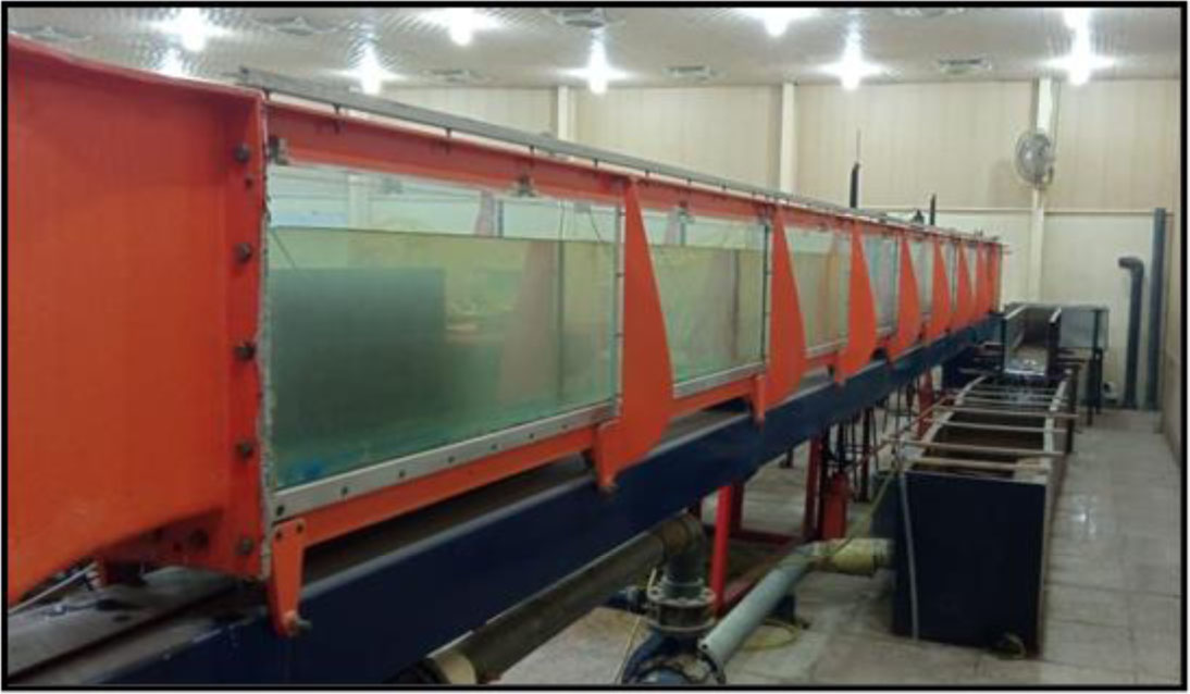
Figure 1:
Details of flume used
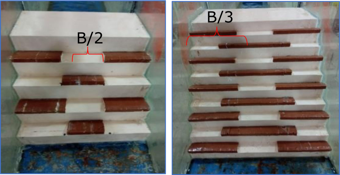
Figure 2:
The experimental models
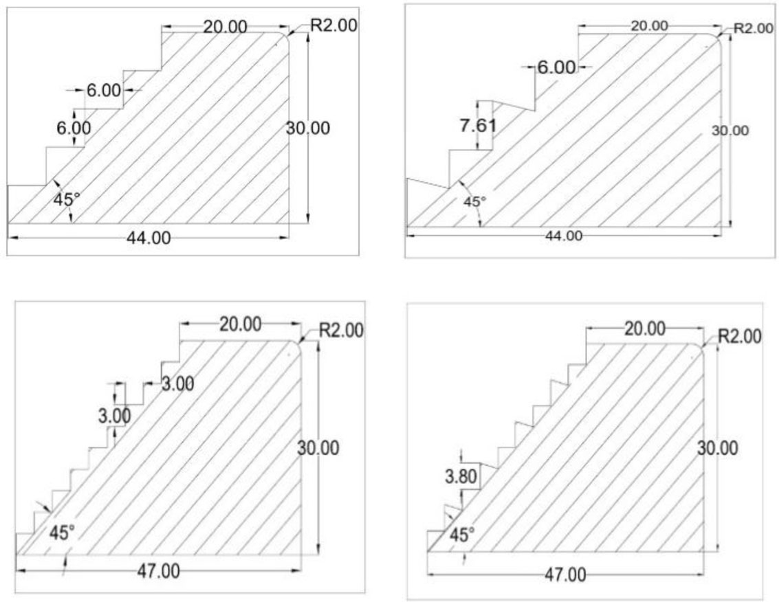
Figure 3:
Stepped spillway models
Table 1:
Characteristics of models
| Model | Main angle (degree) | Height of steps (cm) | Length of steps (cm) | Number of steps | Model Details |
|---|---|---|---|---|---|
| M1 | 45 | 6 | 6 | 5 | Uniform without baffle |
| M2 | 45 | 6 | 6 | 5 | Uniform with B/2 baffle |
| M3 | 45 | 6 | 6 | 5 | Uniform with B/2.5 baffle |
| M4 | 45 | 6 | 6 | 5 | Uniform with B/3 baffle |
| M5 | 45 | - | 6 | 5 | Non-uniform without baffle |
| M6 | 45 | - | 6 | 5 | Non-uniform with B/2 baffle |
| M7 | 45 | - | 6 | 5 | Non-uniform with B/2.5 baffle |
| M8 | 45 | - | 6 | 5 | Non-uniform with B/3 baffle |
| M9 | 45 | 3 | 3 | 10 | Uniform without baffle |
| M10 | 45 | 3 | 3 | 10 | Uniform with B/2 baffle |
| M11 | 45 | 3 | 3 | 10 | Uniform with B/2.5 baffle |
| M12 | 45 | 3 | 3 | 10 | Uniform with B/3 baffle |
| M13 | 45 | 3.8 | - | 10 | Non-uniform without baffle |
| M14 | 45 | 3.8 | - | 10 | Non-uniform with B/2 baffle |
| M15 | 45 | 3.8 | - | 10 | Non-uniform with B/2.5 baffle |
| M16 | 45 | 3.8 | - | 10 | Non-uniform with B/3 baffle |
2.2. Discharge Calibration
The discharge of the flume is measured by the flowmeter attaches to the pipe outside a pump. The discharge of each run can be found by dividing the volume of water (taken after 5-10 minutes) from begging of each run that passes from the flowmeter over time calculated at the same period. A specific calibration is performed to verify the consistency of the measured discharge from the flowmeter with the actual discharge. The accumulative volume of water is measured with a known-volume container and a stopwatch, and eight different discharges are taken to strengthen the relationship's dependability (each discharge is repeated eight times and its average is obtained). The discharge measured by the flowmeter and the discharge of the canal is measured by volume container and stopwatch is plotted in Figure 4.
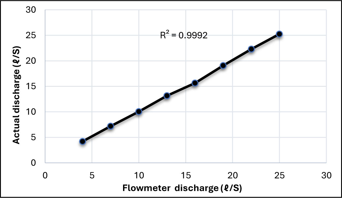
Figure 4:
Discharge calibration curve
2.3. Theoretical Work
Energy upstream and downstream of the spillway can be calculated to determine the energy dissipation rate:
Where:∆E = different between upstream and downstream energy of the stepped spillways' structure,
Eo = energy upstream of spillway,
E1 = energy downstream of spillway.
Energy upstream of spillway is a calculation at critical section by (Simões et al, 2010).
Where:
Eo = maximum energy of stepped spillways crest,
Hdam = Hspilway = 30 cm,
Where:
E1 = downstream energy of stepped spillway,
y1 = water depth of toe,
V1 = Velocity at depth y1,
α = kinetic correction coefficient, for turbulent flow, generally equal to 1 (Simões et al, 2010),
g = gravitational accelerations.
2.4. Dimensional Analysis
Geometric characteristics of the model, Flow characteristics, and Fluid properties are three groups that the discharge over stepped spillway is a function of them, these variables are shown in Table 3.
2.5. Statistical Evaluation
The coefficient of determination (R2) can be calculated by equation (5), will be used to measure how the predicted values of ∆E match the observed values. Also, root mean square error (RMSE) by equation (6), mean square error (MSE) by equation (7), and mean absolute error (MAE) by equation (8).
Where:
R2 - the coefficient of determination,
dso - the observed value,
dsp is the predicted value,
- the mean value of dso,
n - the amount of data.
The following relationship is suggested to different between upstream and downstream energy of the stepped spillway's structure depending on the experimental data.
Table 3:
The classification of parameters affected in (MLT)
| Variable | Definition | Dimension |
|---|---|---|
| Fluid properties | ||
| P | Mass flow density | ML−3 |
| μ | Dynamic viscosity | ML−1T−1 |
| G | Gravity of acceleration | LT−2 |
| Flow characteristics | ||
| y | the flow depth over the crest level in upstream spillway | L |
| yc | Critical depth of flow | L |
| y1 | flow depth just downstream the spillway | L |
| v1 | water velocity just downstream the spillway | LT−1 |
| vc | Critical velocity over the spillway | LT−1 |
| ΔE | the total energy loss | - |
| Spillway geometry properties | ||
| h | the step height | L |
| H | the total height of the spillway | L |
| l | the step length | L |
| B | the channel width | L |
| N | the number of steps | - |
3. Results and Discussion
Since it can no longer be completely turned back into its original form, energy appears to have disappeared once it has changed from one type (like potential energy) to another (like kinetic energy). One frequent dissipative process that cannot be fully converted back into mechanical energy is friction, which converts mechanical energy into thermal energy. As a result, some mechanical energy has been transformed into thermal energy. Consequently, it appears that energy dissipation is an inexorable process.
Relationship between ∆E/E0 % and Froude number for Stepped Spillway at 45 degrees for four different conditions of (uniform five stepped spillway) the first case without baffle, while the other cases were with baffle ratio (B/2, b/2.5 and B/3) are shown in Figure 5. All selected conditions show fluctuated behaviour and are changeable depending on Froude numbers and changes in energy dissipations. For the current condition sample, M2 with a uniform 5-stepped spillway with a B/2 baffle recorded the highest energy dissipation comparison with sample M1 without a baffle block.
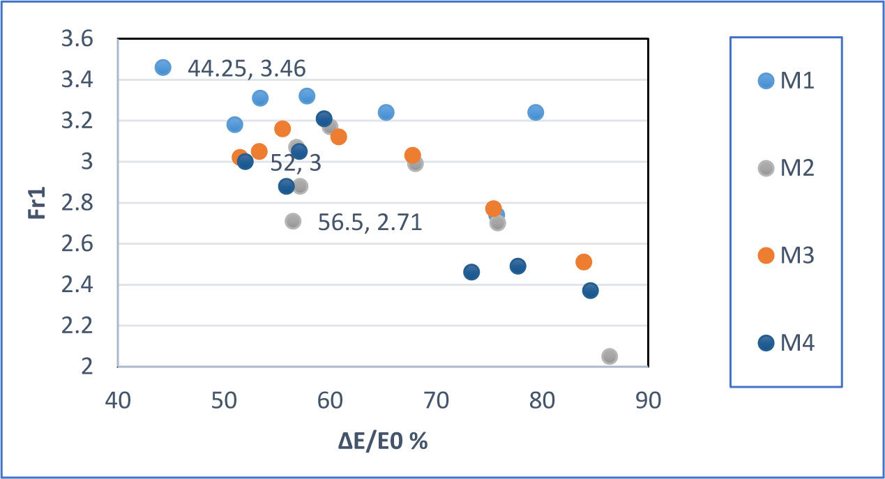
Figure 5:
Relationship between Froude number and ∆E/E0 % for uniform 5 stepped spillway
Relationship between ∆E/E0 % and Froude number for Stepped Spillway at 45 degrees for four conditions (nonuniform 5 stepped spillway). In order to identify the effect of (non-uniform 5-stepped spillway) on the dissipation of energy. Figure 6 shows four conditions without and with baffles block with three different distributions. However, in the current comparison sample, M6 with a non-uniform 5-stepped spillway with a B/2 baffle ratio recorded the highest energy dissipation comparison with sample M8 with a B/3 baffle block ratio.
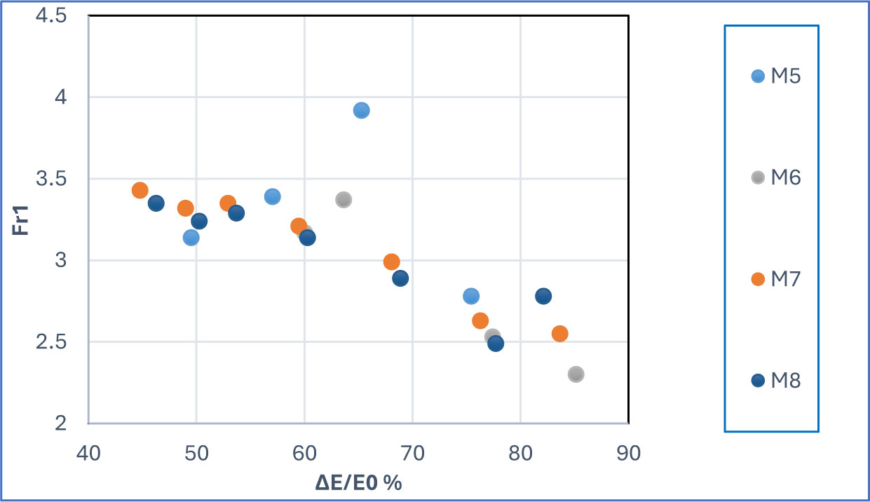
Figure 6:
Relationship between Froude number and ∆E/E0 % for non-uniform 5 stepped spillway
Figure 7 shows relationship between ∆E/E0 % and Froude number for Stepped Spillway at 45 degrees for four conditions (uniform ten stepped spillway). For the current condition sample, M11 with a uniform ten-stepped spillway with a B/2.5 baffle recorded highest energy dissipation comparison with sample M9 without a baffle block.
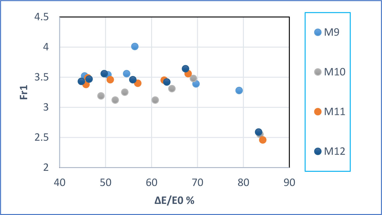
Figure 7:
Relationship between Froude number and ∆E/E0 % for a uniform 10-stepped spillway
Figure 8 shows relationship between ∆E/E0 % and Froude number for Stepped Spillway at 45 degrees for four conditions (non-uniform 10-stepped spillway). For the current condition, sample M14 with a non-uniform 10-stepped spillway with a B/2.5 baffle recorded highest energy dissipation comparison with sample M16 with a B/3 baffle block ratio.
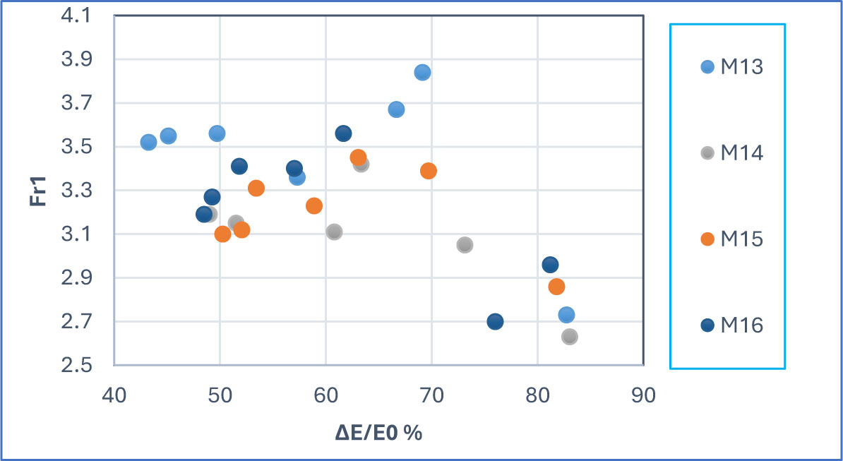
Figure 8.
Relationship between Froude number and ∆E/E0 % for a non-uniform 10-stepped spillway
Using cross-sections of its first conjugated depth as just a starting point, the hydraulic jump's length (Lj) was calculated (h1). The last cross-sectional area is hard to locate, nevertheless. It is due to the intense turbulence in the hydraulic leap and the immediate area downstream of it, which causes ongoing changes in the water stream's characteristics (Wu & Rajaratnam, 1996; Kozioł et al., 2017; Habibzadeh et al., 2016). The cross-section with standing water at the surface was suggested by (Hager, 2018) to be categorized as the hydraulic jump's conclusion. The distance between the first conjugate depth or a cross-section is known as the water roller's length. This process appears to be the most suited since it makes determining length simple and accurate. However, Figure 9 gives relationship between hydraulic jump length and discharge for Stepped Spillway at 45 degrees for four conditions (uniform 5-stepped spillway). The first case was without baffle, while the other cases were with baffle ratio (B/2, b/2.5, and B/3). All selected conditions show that the hydraulic jump length increased with the flow discharge. For the current condition, sample M2 with a uniform 5-stepped spillway with a B/2 baffle recorded the shortest hydraulic jump length comparison with sample M1 without a baffle block.
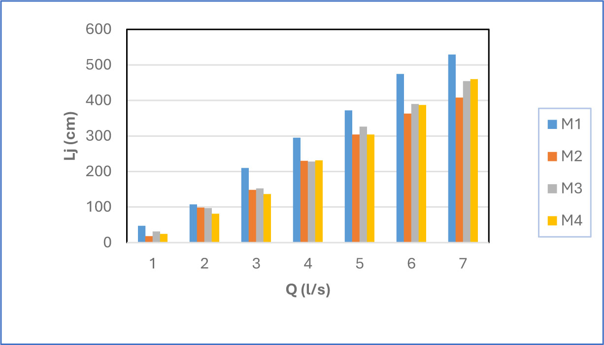
Figure 9:
Relationship between hydraulic jump length and discharge for a uniform 5-stepped spillway
Figure 10 shows relationship between hydraulic jump length and discharge for Stepped Spillway at 45 degrees for four conditions (non-uniform 5-stepped spillway). For the current condition, hydraulic jump length fluctuated with discharge, where in low discharge, M5 has the shortest hydraulic jump length, while in high flow discharge sample M5 recorded the longest hydraulic jump length, and the use of baffles in different ratios reduced the hydraulic jump length in high flow discharge.
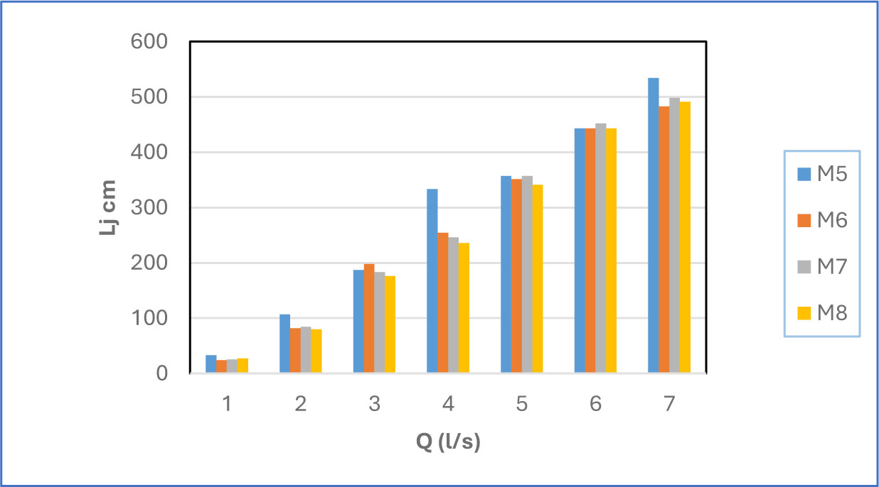
Figure 10:
Relationship between hydraulic jump length and discharge for a non-uniform 5-stepped spillway
Figure 11 shows relationship between hydraulic jump length and discharge for Stepped Spillway at 45 degrees for four conditions (uniform 10-stepped spillway). All selected conditions show that the hydraulic jump length increased with the flow discharge. For the current condition, sample M10 with a uniform 10-stepped spillway with a B/2 baffle recorded the shortest hydraulic jump length comparison with sample M9 without a baffle block.
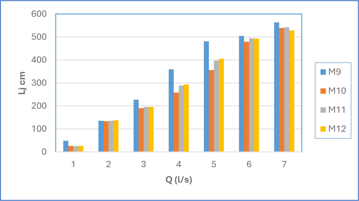
Figure 11:
Relationship between hydraulic jump length and discharge for the uniform 10-stepped spillway
Figure 12 shows relationship between hydraulic jump length and discharge for Stepped Spillway at 45 degrees for four conditions (non-uniform 10-stepped spillway). For the current condition, hydraulic jump length fluctuated with discharge, whereas M13 has the shortest hydraulic jump length in low discharge. In contrast, M13 recorded the longest hydraulic jump length in the high flow discharge sample, and using baffles in different ratios reduced the hydraulic jump length in high flow discharge.
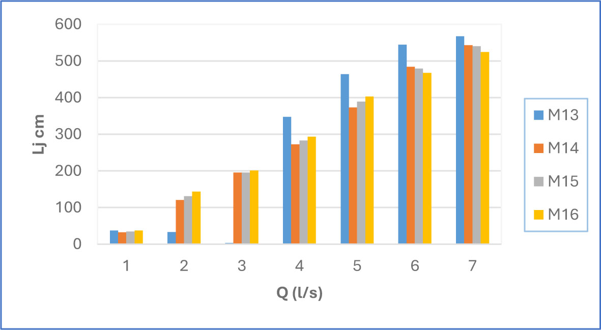
Figure 12:
Relationship between hydraulic jump length and discharge for a non-uniform 10-stepped spillway
Figure 13 shows the performance of the predicted values of (∆E) using equations 5, 6, 7, and 8 respectively against the calculated values of (∆E) using equation 4. According to Fig.13 and the values of (R2, RMSE, MSE and MAE), it can be stated that the proposed equation can estimate ∆E with high reliability.
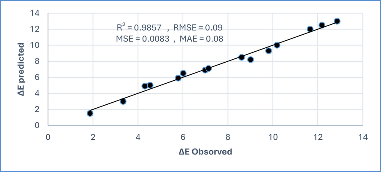
Figure 13:
Comparison of equation 4 with experimental data
4. Conclusion
The hydraulic jump length was significantly reduced for uniform 5-stepped spillways after using baffles compared with other conditions. Sample M2 with a uniform 5-stepped spillway with a B/2 baffle recorded the highest energy dissipation comparison with all other samples with and without baffles block. For all selected situations, increasing the discharge results in a longer hydraulic jump; for all indicated conditions, employing baffles blocks results in a shorter jump. These declines, however, are more noticeable in discharges with high flows. The developed relationships can predict (∆E) with high accuracy. (R2) 0.9857, (RMSE) 0.09, (MSE) 0.0083, and (MAE) 0.08. The study demonstrates that tailoring baffle block placement on stepped spillways can effectively improve hydraulic performance and reduce downstream scour potential.
Acknowledgements
The authors thank the University of Babylon for providing the flume to conduct the experiment.
Notes
[1] Contributed by Author Contributions
N.S. conceived, designed, data interpretation the study and supervised the project. T.S. conducted the experiments and collected the data. W.A. contributed to manuscript drafting. All authors critically reviewed and approved the final version of the manuscript and agreed to be accountable for all aspects of the work.