

The aim of this paper is to assess the condition of bridge superstructures that were inspected and found to have major defects that could influence their structural capacity or long-term durability. The assessed bridge superstructures were rated between IV and VI on a seven-point scale (Czech Standards Institute, 2018). Typical defects associated with this type of standardized girder include corroded prestressing tendons, deficiencies in longitudinal joints between girders, and anchorage zone problems. Other common issues may involve leakage, concrete deterioration, unbonded reinforcement covers, and related defects. The inspection concentrated on a detailed assessment of prestressing reinforcement corrosion, a comparison of the actual and design concrete strength classes, a visual survey, and an analysis of chloride ion content in the concrete.
The inspection was carried out on bridges of one to nine spans located in the Czech Republic, supported by steel roller and fixed bearings, elastomeric bearings, and pot bearings. These structures mainly serve to carry roads over rivers, streams, and other motorways. The superstructures are built from standardized I-73 girders with clear spans ranging from 21 to 30 meters. The substructures are made either of reinforced concrete or of a combination of plain and reinforced concrete. Figure 1 presents a typical bridge cross-section with I-73 girders in the superstructure, while Figure 2 illustrates the reinforcement of the 21-meter-long I-73 girder with prestressing tendons.
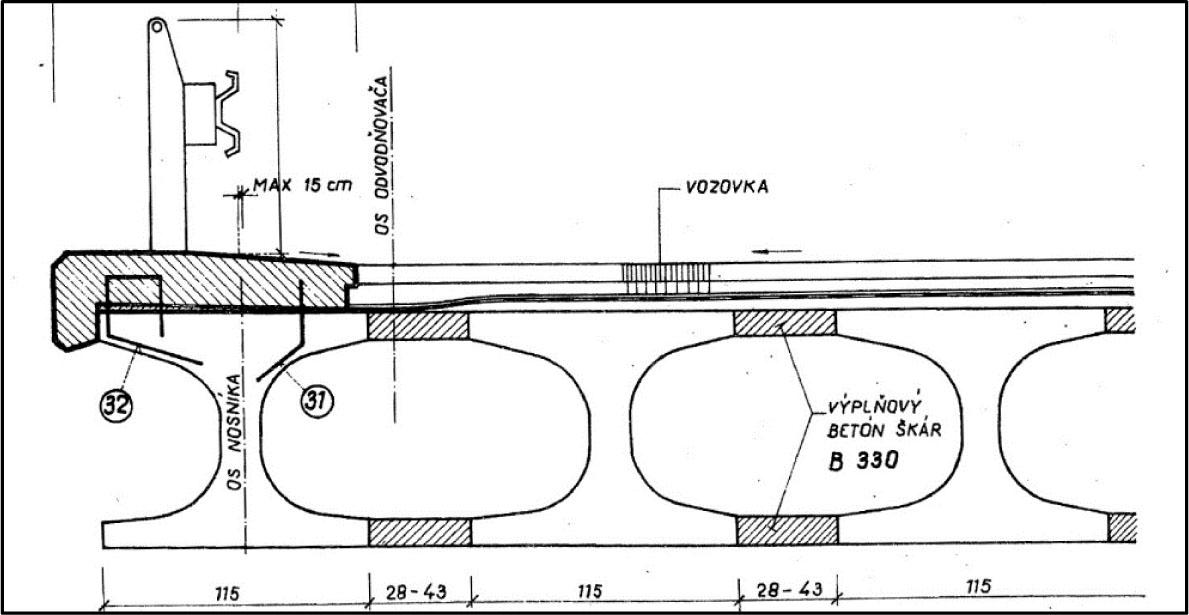
Cross-section of a bridge, where the superstructures consist of I-73 girders (Dopravoprojekt, 1973)
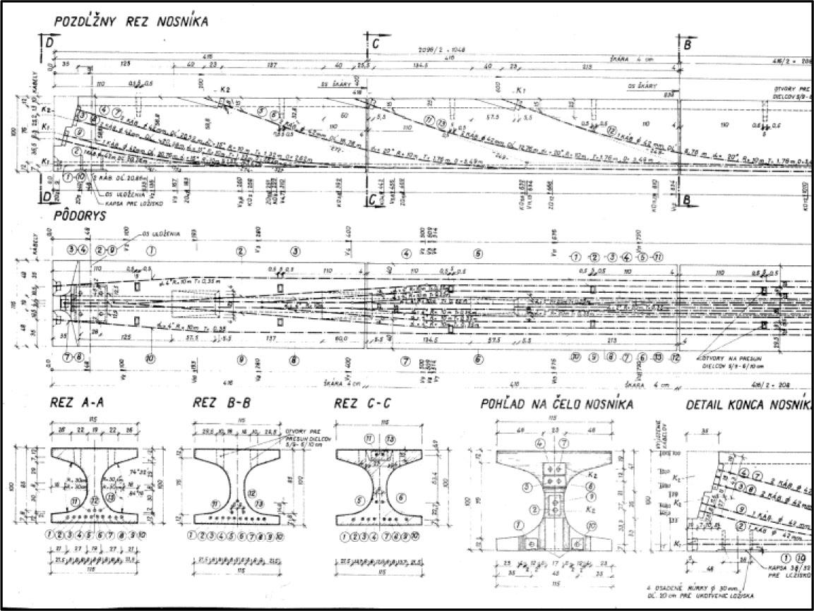
Reinforcement of the 21-meter-long I-73 girder with prestressing tendons (Dopravoprojekt, 1973)
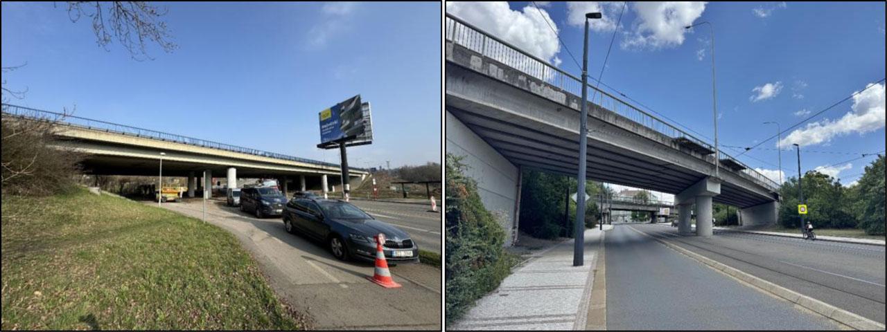
Three-span bridge (left) and two-span bridges (right), both located in Prague
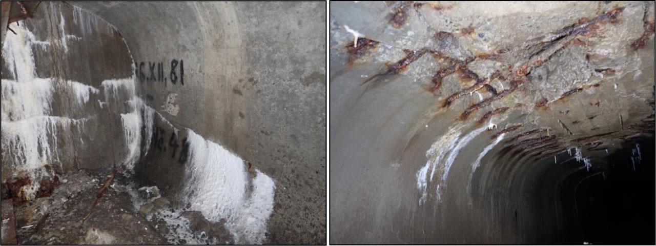
Significant active water leakage into the cells between the I-73 girders. Visible surface degradation of the concrete and exposed reinforcement. Observable paths of prestressing reinforcement (cracks and leachates)
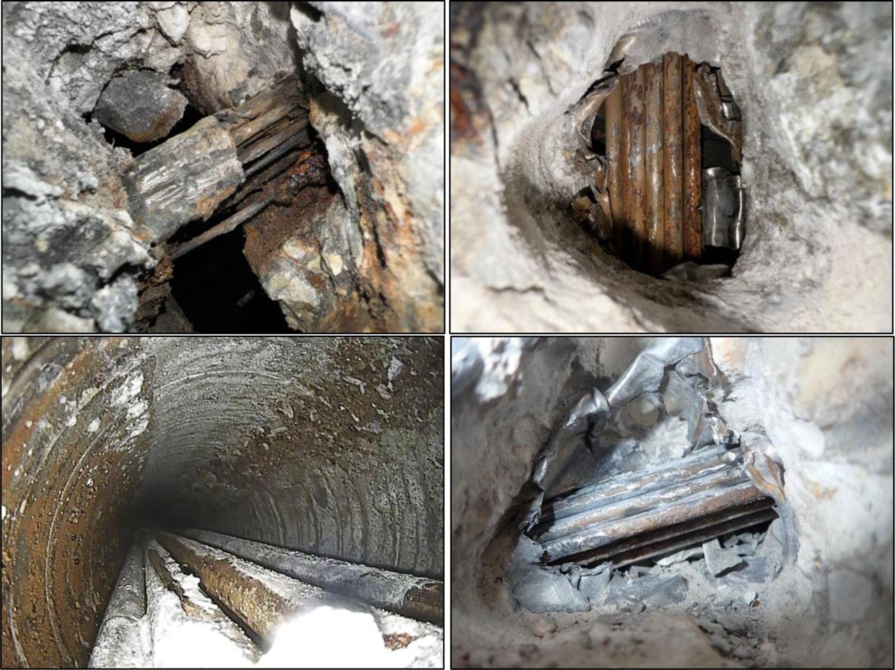
Presence of non-grouted tendon ducts and corrosion of prestressing strands and wires
Presence of ungrouted tendon ducts and corrosion affecting the prestressing strands
The standard I-73 girders from 1973 replaced the I-67 and I-62 girders. The new standard design was developed due to the new bridge load code (issued in 1969) and the use of new types of steel. The girders were produced in segmental lengths of 21, 24, 27, and 30 m (the span always 1 m shorter), with heights of 100, 110, 125, and 140 cm, with the same flange width of 115 cm, flange end thickness of 12 cm, and web thickness in the middle of 19 cm. The longitudinal joint between girders was designed with a width of 28–43 cm, with steel inserts embedded in the top and bottom flanges protruding into the joint area. A girder manufactured in a precast plant was assembled on site from 5 segments (longitudinal joints between girders of 4 cm width, filled with mortar without reinforcement, with insertion of pipes approx. 20 cm long into the tendon ducts; alternatively glued joints without pipes). Girders casts were produced only in on-site formwork. The girders are designed from concrete grade B500, the joints from concrete grade B330. Mild reinforcement is used of grade 10425 (stirrups 10216), and the prestressing reinforcement consists of smooth patented wire ϕ4.5 mm with an ultimate strength of 16,500 kp/cm2 and yield strength of 12,000 (13,500) kp/cm2. The tendon ducts have a diameter of 42 mm, made of corrugated steel tubes and injected with grout.
Although inherently subjective, visual inspection remains an essential part of bridge assessment. In bridges with superstructures made of prestressed precast girders, the inspection primarily aims to identify reinforcement corrosion, concrete defects or cracking, leakage areas, and related issues. Such deficiencies can have a substantial impact on the durability and service life of the bridge.
Concrete cores with diameters ranging from 50 to 100 mm were extracted from the bridge superstructures for carrying out destructive tests of concrete compressive strength. Both sampling and testing procedures followed the standards ČSN EN 12504-1 (Czech Standards Institute, n.d.) and ČSN EN 12390-3 (Czech Standards Institute, n.d.). The determination of core diameters was based on the spacing of the prestressing reinforcement. The concrete strength classes corresponding to the samples are shown in Table 1. The results of destructive tests verified that the strength class of all eight inspected superstructures met or exceed the B 500 requirements outlined in the type of documentation (Czech Standards Institute, 2018), equivalent to today's C 35/45 class.
Summary of Concrete Test Results
| Bridge no. | Structural condition of superstructure (Scale I–VII) | Strength class of concrete | Conversion of Cl- to cement quantity of approximately 420 kg in 1 m3 of concrete [%] | Concrete carbonation depth [mm] | ||
|---|---|---|---|---|---|---|
| ČSN 736221 | ČSN EN 206+A2 | Depth 0 – 15 [mm] | Depth 15 – 30 [mm] | Depth 30 – 45 [mm] | ||
| 1 | VI | C 45/55 | 0.45 | 0.32 | 0.16 | 1 – 7 |
| 2 | V | C 45/55 | 0.71 | 0.58 | 0.37 | 3 – 6 |
| 3 | VI | C 50/60 | 1,17 | 0.70 | 0.35 | 3 – 12 |
| 4 | V | C 40/50 | 0,89 | 0.70 | 0.44 | 4 – 13 |
| 5 | V | C 45/55 | 0.15 | 0.11 | 0.07 | 2 – 8 |
| 6 | IV | C 40/50 | 0.25 | 0.12 | 0.05 | 1 – 7 |
| 7 | VI | C 45/55 | 0.78 | 0.59 | 0.44 | 1 – 9 |
| 8 | V | C 35/45 | 0.38 | 0.30 | 0.15 | 2 – 10 |
Assessment of concrete carbonation depth and its comparison with the reinforcement cover was performed along the full extent of the bridge superstructures. The progression of reinforcement corrosion is influenced by multiple factors, including contaminants in the concrete, e.g., acids, chloride ions, and other aggressive compounds, environmental humidity, water saturation of the pore system, reinforcement cover thickness, and carbonation depth. To more accurately determine the reinforcement cover in the reinforced concrete girders, non-destructive testing methods were also applied. The results show that, in most of the monitored bridge superstructures, only a limited portion of the reinforcement—primarily the stirrups - falls within the carbonated concrete layer, leaving it vulnerable to corrosion due to the loss of alkalinity. This problem is mainly caused by insufficient concrete cover. In comparison, the residual reinforcement, particularly the prestressing strands, continues to benefit from sufficient protection provided by the concrete's alkalinity.
On each bridge superstructure, the prestressing reinforcement of I-73 girders was examined to assess the positioning and condition of the prestressing strands. The evaluation followed the procedure outlined in (Klokner Institute, CTU in Prague, 2019), with the condition of the strands classified into six levels according to a corrosion damage rating scale (Table 2). During the corrosion evaluation, corrosion product samples, frequently accompanied by fine cement grout particles, were gathered and examined. Their composition was examined using X-ray fluorescence (XRF), while phase identification was analyzed by X-ray diffraction (XRD). Laboratory analyses confirmed that corrosion initiation and progression were primarily driven by chloride anions (Cl−) originating from de-icing salts (NaCl). Chloride anions were found at unusually high concentrations within the corrosion products.
Condition Assessment of Prestressing Reinforcement
| Condition of reinforcement | Corrosion damage | Damage description |
|---|---|---|
| Level 1 | Reinforcement showing no signs of corrosion. | |
| Level 2 | The reinforcement exhibits only localized surface corrosion, with no impact on cross-sectional area. | |
| Level 3 | Surface corrosion is present without accumulation of corrosion products, and its impact on cross-section reduction and mechanical properties is negligible. | |
| Level 4 | Surface corrosion is fully distributed, with corrosion products peeling off. Cross-sectional area reduction has already reached approximately 2 – 4%; this type of corrosion represents a borderline case in terms of its negative effect on mechanical properties. | |
| Level 5 | The strand exhibits fully spread surface corrosion, with extensive peeling of corrosion products. Noticeable deformation and cross-sectional area loss are significant, reaching several tens of percent. | |
| Level 6 | Noticeable deformation of the strand is observed, with some wires broken or fully corroded. Cross-sectional area is significantly reduced, by 50 % or more. |
From the inspections carried out via destructive boreholes, the following conclusions are drawn:
- ○
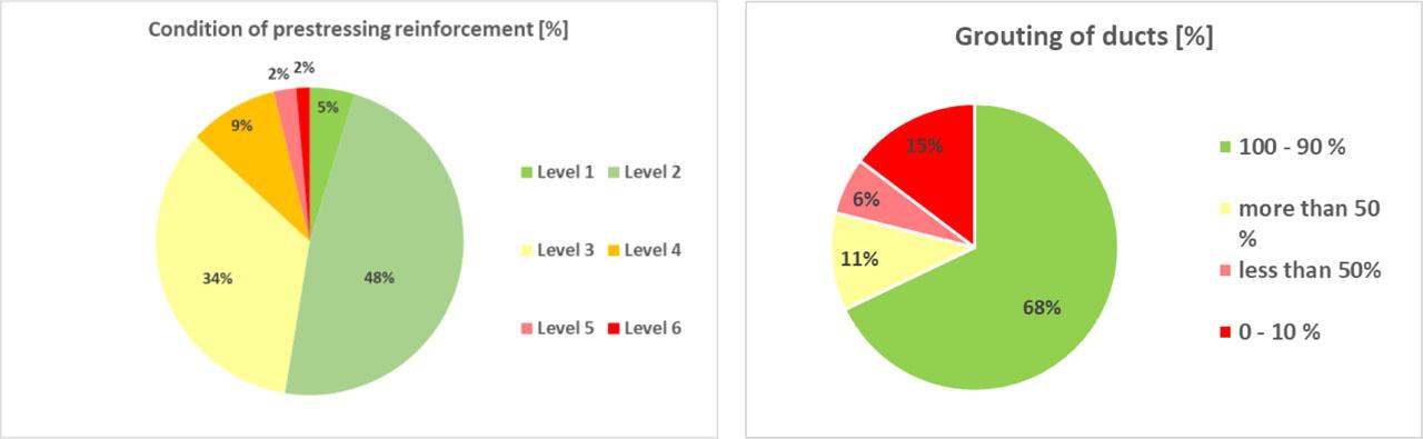
As seen in Fig. 6, 5% of the total 213 boreholes across 8 bridges were classified as Level 1, 48% as Level 2, 34% as Level 3, 9% as Level 4, and only 4% as Level 5 or below.
- ○
As seen in Fig. 6, the ducts were filled to the specified level of 90–100% of their capacity in 68% of the 213 boreholes, 50–90% in 11%, 10–50% in 6%, and 15% were non-grouted.
- ○
The most critical areas were identified as the outer girders and, in some cases, the longitudinal joints between girders, where prestressing reinforcement is especially susceptible to corrosion due to degradation of joint materials and leakage caused by defective bridge deck waterproofing.
- ○
The regions beneath the girder anchorage zones represent another critical area. For curved tendons, the grouting mixture inside the ducts tends to settle over time, leaving sections of the prestressing reinforcement unprotected and thus more susceptible to corrosion.

Prestressing Reinforcement Condition Evaluated by Girder Location
For all eight road bridges, the inspection of superstructures did not reveal any static defects or failures that would directly endanger the overall load-bearing capacity. Moreover, destructive compression strength tests confirmed that the concrete strength classes met or exceed the B 500 specifications in the type of documentation (Dopravoprojekt, 1973), corresponding to today's C 35/45 class.
The effects of carbonation were limited to a part of the shear reinforcement in the girders, primarily because of insufficient concrete cover. The prestressing reinforcement, however, remains embedded in non-carbonated concrete, where it is still protected by the material's alkalinity.
According to the chloride content analysis, at a sampling depth of 30–45 mm (corresponding to the prestressing reinforcement cover) the chloride concentrations in the inspected prestressed girders were relatively high, exceeding the limits specified in ČSN EN 206+A2 (Czech Standards Institute, 2021) in four of the eight bridges. In contrast, the grout consistently exhibited low chloride ion content, satisfying the requirements of ČSN EN 206+A2 (Czech Standards Institute, 2021) in all cases. Elevated chloride levels were most frequently detected near leakage zones and in the outer girders.
The corrosion assessment involved collecting corrosion products, frequently accompanied by fine-grained cement grout fragments, and subjecting them to elemental analysis via X-ray fluorescence (XRF) and phase identification using X-ray diffraction (XRD). Results showed that the prestressing reinforcement tendons experience severe, localized, and unpredictable corrosion damage (classified between levels 4 and 6) mainly caused by chloride anions (Cl−) from de-icing salts (NaCl). The extent and localization of the damage were strongly influenced by moisture penetration into the reinforcement zone, caused by leakage or condensation (Debbal et al., 2025).
The outer girders and, in some cases, the longitudinal joints between girders were identified as the most problematic areas, where prestressing reinforcement is especially susceptible to corrosion. This increased susceptibility results from the degradation of joint materials and leakage caused by the failure of the bridge deck's waterproofing system. The areas below the girder anchorage zones represent another source of concern. In curved tendon ducts, grout settlement during grouting can leave parts of the prestressing reinforcement insufficiently covered, increasing its susceptibility to corrosion.
A complete renewal of the waterproofing system is the only effective measure to mitigate the identified superstructure defects and prevent further loss of water. Advanced strengthening approaches, such as UHPC application, can help enhance the bridge deck and increase its service life. During reconstruction works, careful evaluation of the prestressing anchors and verification of the grout quality in the ducts are necessary. However, given the difficulty of inspecting the anchorage zones of the inner girders and the presence of active leakage, it is unlikely that these superstructures will achieve the intended service life of 100 years (Vičan et al., 2023; Kralovanec et al., 2024).