

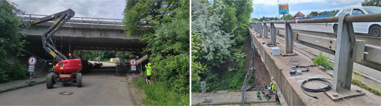
Figure 1:
Bridge on Road I/50 in Brno: a) underside view, b) installation of measuring equipment”
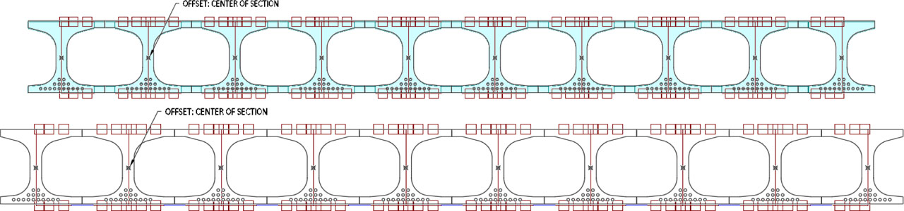
Figure 2:
Beam model assembled using rigid links
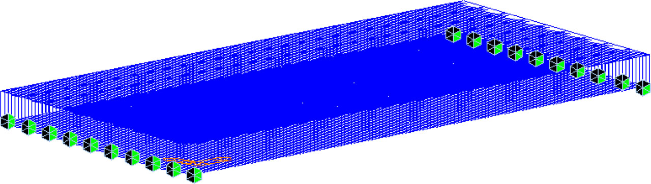
Figure 3:
Axonometric view of the frame structure with supports

Figure 4:
Structure displayed with cross-section thicknesses and shapes

Figure 5:
Visualization of the structure with thicknesses and cross-sections

Figure 6:
Detail of transverse link modelling

Figure 7:
Position of the prestressing reinforcement

Figure 8:
Cross-sectional properties: a) full section, b) weakened section
Table 1:
Material properties – concrete
| BEAM (C30/37) | Property | Value [−] |
|---|---|---|
| Modul of elasticity | E | 38,5 GPa |
| Compressive strength | fck | 30 MPa |
| Tensile strength | fctm | 2,9 MPa |
| Unit weight | γ | 25,5 kN/m3 |
| Poisson’s ratio | ѵ | 0,2 |
Table 2:
Material characteristics – prestressing reinforcement
| PRESTRESSING CABLES | Property | Value [−] |
|---|---|---|
| Modul of elasticity | E | 190 GPa |
| Ultimate tensile strength | ϭp | 1130 MPa |
| Strand area | Ap1 | 15,9*10−6 m2 |
| Unit weight | γ | 25,5 kN/m3 |
| Poisson’s ratio | ѵ | 0,3 |
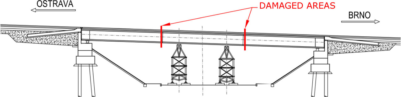
Figure 9:
Location of intentional damage (marked in red)
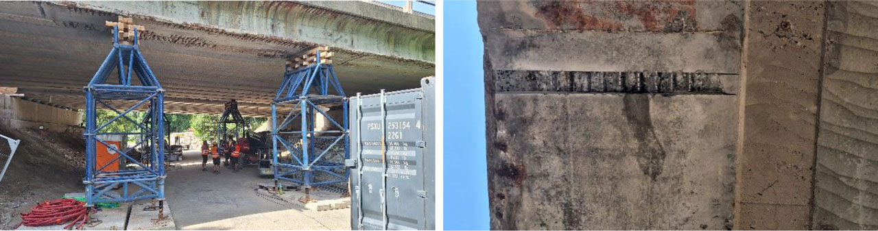
Figure 10:
Damage to the edge girders before next measurement
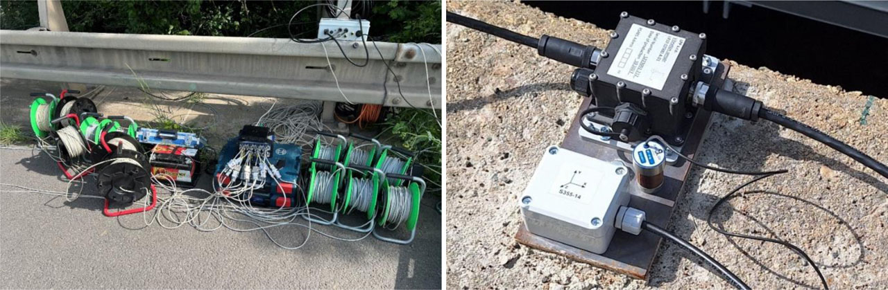
Figure 11:
Bridge measurements: a) placement of measuring equipment, b) Seika B1 accelerometer
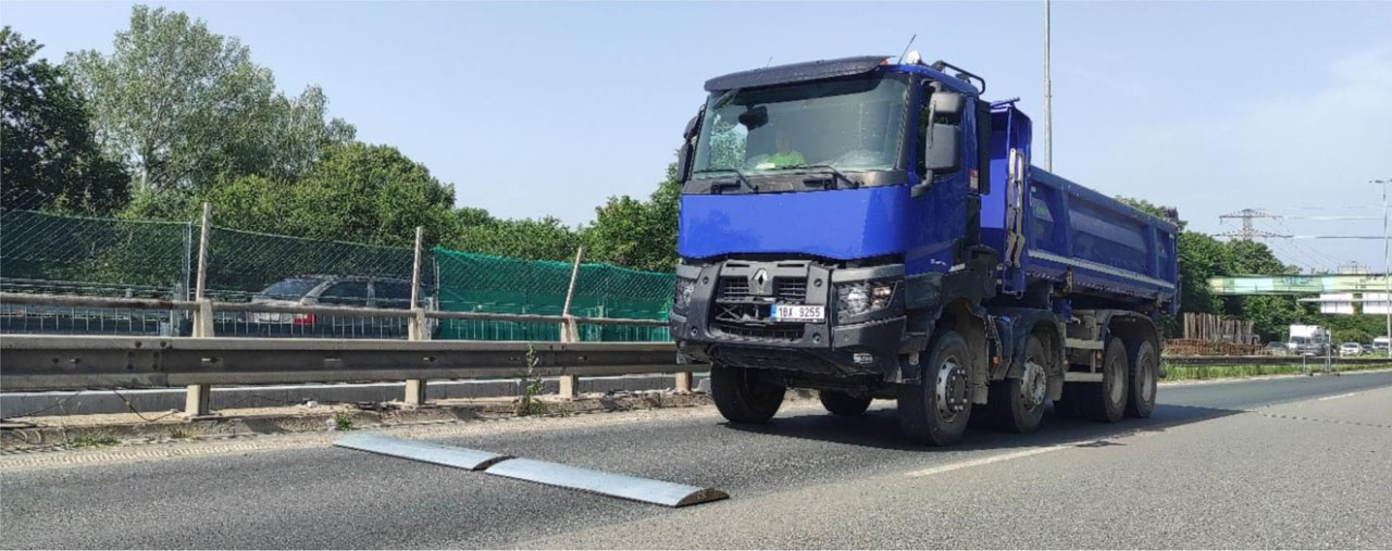
Figure 12:
Truck crossing
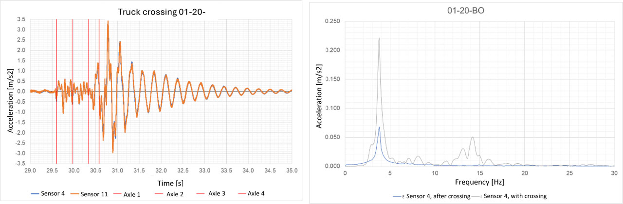
Figure 13:
Excitation at L/2 on the left side: a) acceleration record, b) frequency spectrum