

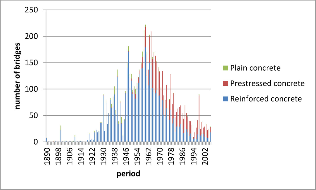
Figure 1:
Number of road bridges depending on the year of construction, comparison of reinforced concrete and prestressed concrete bridges
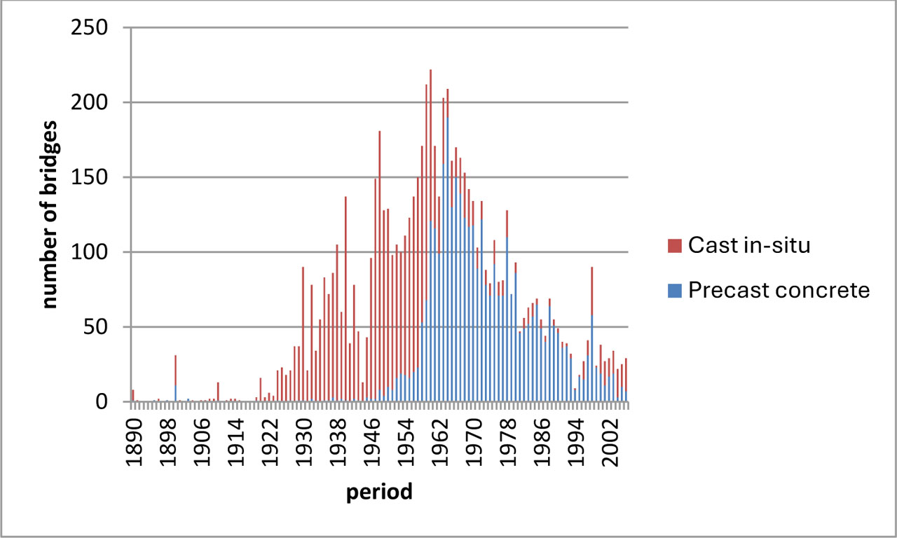
Figure 2:
Number of road bridges depending on the year of construction, comparison of cast-in-situ and prefabricated concrete bridges
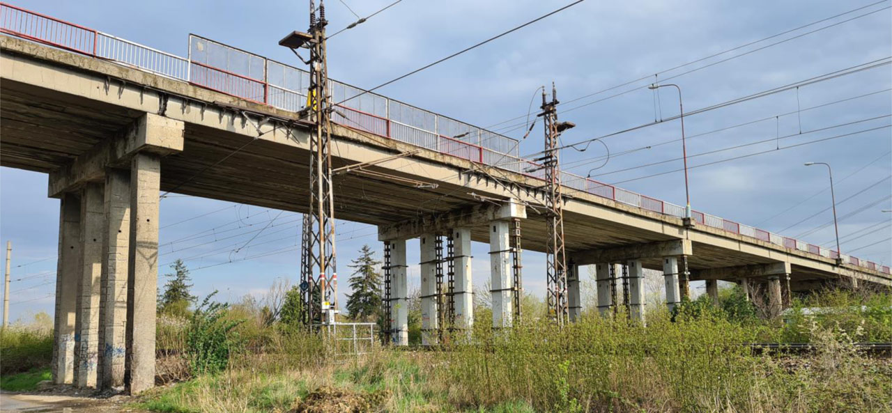
Figure 3:
View of the bridge on Bojnicka Street
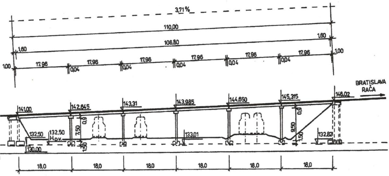
Figure 4:
Longitudinal section of the bridge, dimensions in [m]
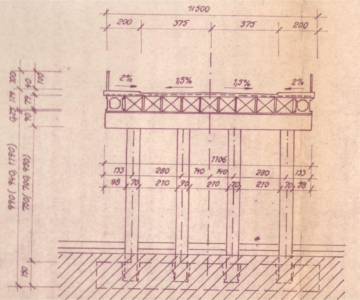
Figure 5:
Transverse section of the bridge with intermediate support, dimensions in [cm]
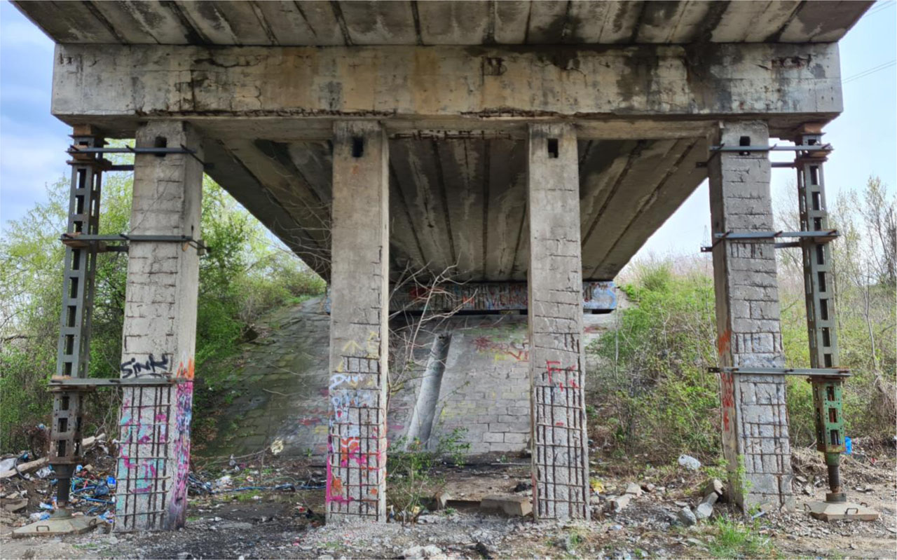
Figure 6:
View on the substructure with temporary support of the crossbeam
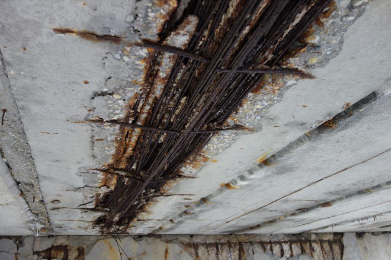
Figure 7:
View of corroded prestressing wires
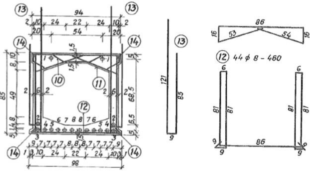
Figure 8:
Cross-section of the girder KA-67 with reinforcement and prestressing tendons, dimensions in [cm]
Table 1:
Load-bearing capacity of the bridge deck
| Assessment | Line | Level of prestress | Normal capacity | Exclusive capacity | ||
|---|---|---|---|---|---|---|
| kz,n [-] | Vn [t] | kz,r [-] | Vr [t] | |||
| Stress in concrete limitation SLS | 1 | 100 % | 0.95 | 30.4 | 1.02 | 91.8 |
| 2 | 85 % | 0.58 | 18.6 | 0.61 | 54.9 | |
| 3 | 70 % | 0.19 | 6.1 | 0.18 | 16.2 | |
| 4 | 50 % | 0 | 0 | 0 | 0 | |
| Bending resistance ULS | 5 | 100 % | 1.717 | 54.9 | 1.560 | 140.4 |
| 6 | 85 % | 1.437 | 46.0 | 1.305 | 117.5 | |
| 7 | 70 % | 1.071 | 34.3 | 0.973 | 87.6 | |
| 8 | 50 % | 0.528 | 16.9 | 0.479 | 43.1 | |
| Shear resistance ULS | 9 | 100 % | 1.16 | 37.1 | 1.16 | 104.4 |
| 10 | 85 % | 0.93 | 29.8 | 0.91 | 81.9 | |
| 11 | 70 % | 0.73 | 23.4 | 0.69 | 62.1 | |
| 12 | 50 % | 0.43 | 13.7 | 0.36 | 32.4 | |
Table 2:
Comparison of the bending moments and deflections between standard and test loads
| Effect of load | Loading | Effectiveness | ||
|---|---|---|---|---|
| Design En | Test Etest | Etest/(En) [-] | ||
| Bending moments | 520 kN.m | 293 kN.m | 0.563 | |
| Deflection | (EI)1 = 1299 MN.m2 | 12.6 mm | 7.20 mm | 0.571 |
| (EI)2 = 1489 MN.m2 | 10.5 mm | 5.93 mm | 0.565 | |
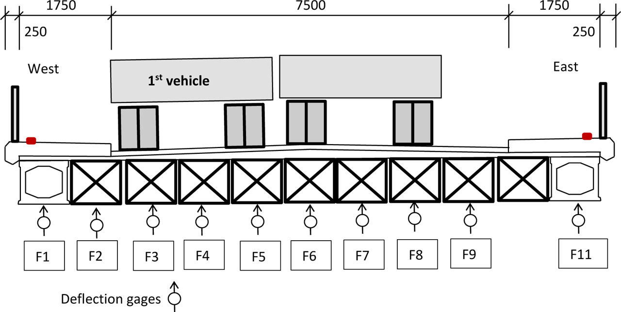
Figure 9:
Positioning of deflection gages and testing load in the most unfavourable position
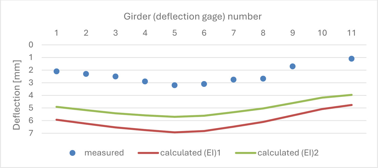
Figure 10:
Comparison of measured deflections and theoretical predictions for the most unfavourable load position

Figure 11:
a) Detailed inspection of critical sections, b) the most unfavourable position of the load during the load test