

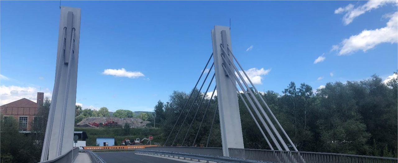
Figure 1:
Cable-stayed bridge over the Rožnovská Bečva near Hrachovec
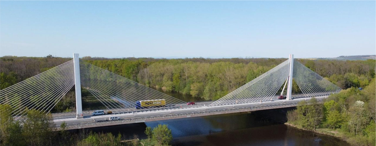
Figure 2:
Cable-stayed bridge over the Elbe River near Poděbrady
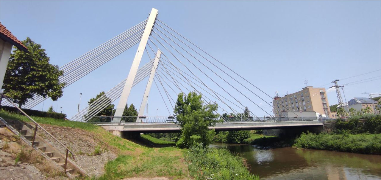
Figure 3:
Cable-stayed bridge over the Svratka River in Židlochovice
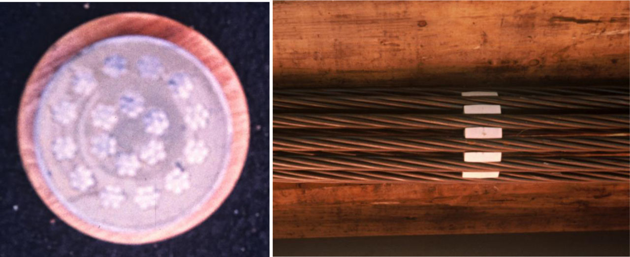
Figure 4:
Stayes: a) routing of prestressing strands in a pipe, b) spacers between prestressing strands
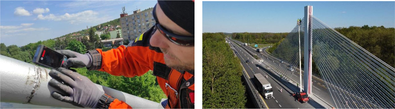
Figure 5:
Conducting visual inspection and acoustic tracing: a) bridge in Židlochovice with short stayes, and b) vertical measuring sections for long stayes on the bridge near Poděbrady
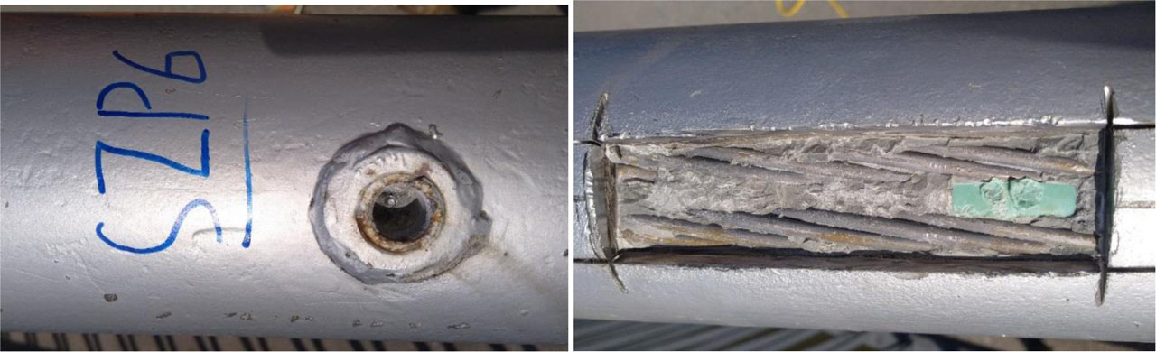
Figure 6:
Drilled semi destructive probe in a stay cable — a) in the socket of the grouting hole, b) through the sheath
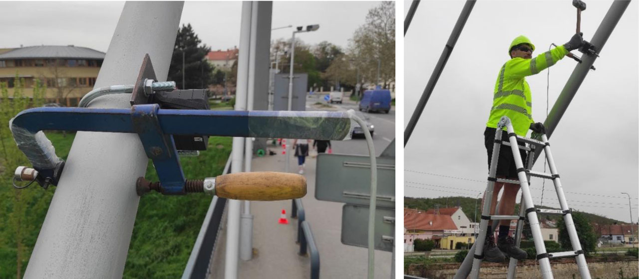
Figure 7:
Conducting dynamic measurement: a) measuring fixture with mounted accelerometer, b) excitation by striking with a hammer fitted with a rubber head
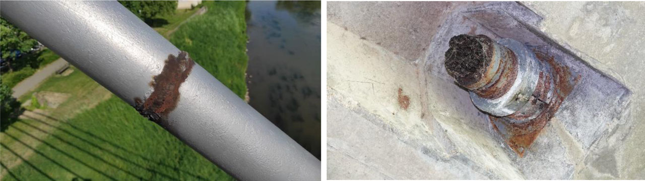
Figure 8:
Results of visual inspection: a) corrosion of external sheath joints, b) corrosion damage to the protective coating system of the anchorage and missing anchorage cover
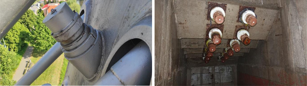
Figure 9:
Condition of anchorages: a) on the pylon, b) in the anchorage chamber of the bridge over the Svratka River in Židlochovice
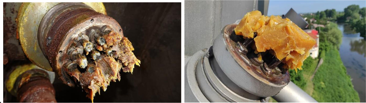
Figure 10:
Example of lubricant condition after removing the protective cover: a) in the anchorage chamber, b) on the pylon
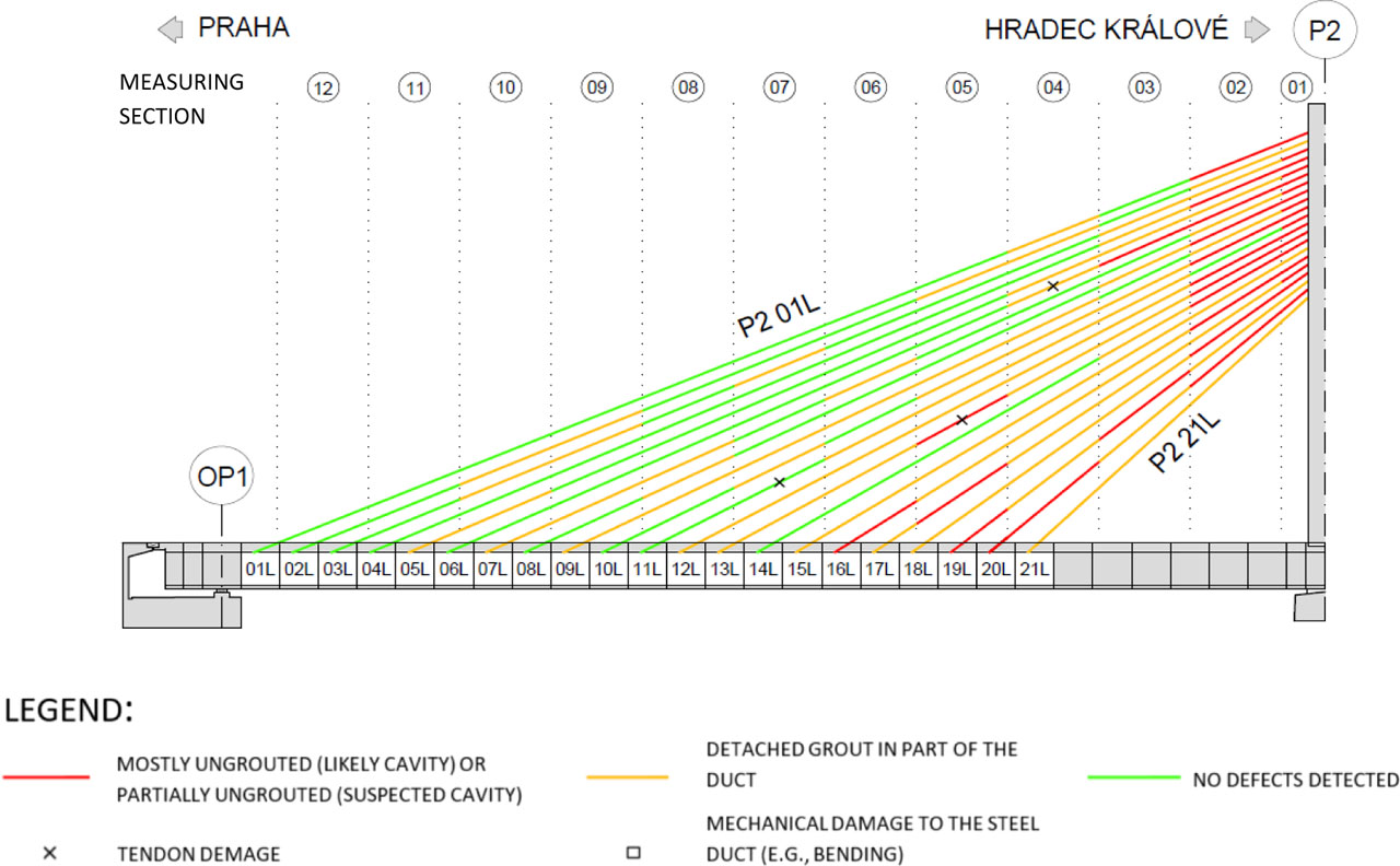
Figure 11:
Condition of grouting for half of harp P3 with stays on the left side of the bridge over the Elbe River near Poděbrady
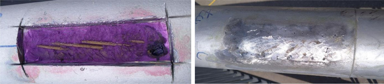
Figure 12:
Cut through probe through the stay cable sheath on the bridge in Židlochovice: a) indicative pH test, b) sealing with a welded steel patch
Table 1:
Calibration tensioning of stay cable Z45L on the bridge near the village of Hrachovec
| Calibration of stay cable tension Z45L | Measured frequency f [Hz] | Stay cable force FV [kN] | Stay cable force according to NAPKO FN [kN] | Comparison [%] |
|---|---|---|---|---|
| Initial condition before rectification | 5.20 | 920 | ||
| Anchor release | 5.34 | 979 | 968 | 101% |
| Required tension | 6.57 | 1567 | 1622 | 97% |
| Overtension before anchoring | 6.81 | 1697 | 1732 | 98% |
| Re-anchoring | x | x |
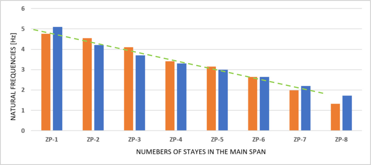
Figure 13:
Comparison of the first natural frequencies of stayes in the main span (orange – left stayes, blue – right stayes, green – expected trend)
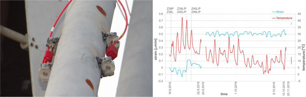
Figure 14:
Strain-gauge measurement: a) installed vibrating-wire strain gauge, b) deformation and temperature record from a selected gauge