

The diagnostics of stay cables in cable-stayed bridge structures represent a key part of the assessment of their structural condition and residual service life. Stay cables transfer the entire load between the bridge deck and the pylons, and therefore their failures-caused, for example, by strand degradation, prestress losses, insufficient grouting, or corrosion processes-may critically compromise the reliability of the whole structure. In practice, a systematic diagnostic survey is therefore applied, combining basic methods (visual inspection, acoustic tracing, grout condition assessment) with advanced procedures based on dynamic testing and strain-gauge monitoring (Geier, De Roeck & Pety, 2005; Nazarian, Hoult & Scott, 2016). These methods enable not only more accurate determination of tensile forces but also timely identification of hidden defects and preparation of input data for cable rectification. In recent years, these approaches have been further complemented by the experience from large-scale load testing and verification measurements, which confirmed their high accuracy and reliability for long-term monitoring of bridge structures (Innocenzi et al., 2022). The use of a combination of standard and advanced methods therefore provides an effective tool for predictive maintenance and allows better planning of interventions aimed at improving operational safety and extending the service life of cable-stay bridges.
For the diagnostics of stays in cable-stayed structures, the Faculty of Civil Engineering in Brno applies, in addition to the basic methodology, an extended approach described by Klusáček et al. (2020) and Nečas et al. (2021). Comparable international experience has been reported by Al-Khateeb et al. (2019), who demonstrated that regularly conducted diagnostic load tests on a cable-stayed bridge provide valuable information on structural response and its long-term evolution. Similar studies emphasize the importance of reliable stay-force determination, effective methods for detecting tension loss in stay cables, and modern approaches to structural health monitoring of cable systems (Zhang, 2021; Kong et al., 2024). Recent research also focuses on the detection of grout voids in tendon ducts and on durability assessment of stay cables (Yee, Yahng, & Cho, 2023; Teichgräber, 2024). This article provides a deeper theoretical basis and extends its application to another structure.
The first diagnosed construction is a bridge structure located in the Zlín region (Vsetín district) near the village of Hrachovec (Figure 1). It is a single-span cable-stayed bridge with a span of 40 m crossing a 3rd class road over the Rožnovská Bečva River. The bridge deck consists of prefabricated prestressed segments (modified KA-girders) supported on a pair of prestressed T-beams. These beams are suspended by stayes from two 10 meter high prefabricated prestressed pylons. The substructure consists of massive monolithic reinforced-concrete abutments with reinforced-concrete bearing thresholds. The bridge was built in 1992 based on a design by the engineering office Dopravní stavby Olomouc.
Cable-stayed bridge over the Rožnovská Bečva near Hrachovec
The second structure is a bridge construction located in the Middle Bohemia region (Nymburk district) near the town of Poděbrady (Figure 2). The bridge is a three-span cable-stayed bridge with spans of 61 × 123 × 61 m, crossing the D11 motorway over the Elbe River. The bridge consists of a precast segmental box-girder structure assembled using the balanced cantilever method. The cable-stayed system is of the harp type, with stays anchored to two pylons positioned above the inner piers and rising to a height of 28 m. The structure is suspended in a single plane along the bridge axis. The bridge was built in 1990 based on a design by the same engineering company.

Cable-stayed bridge over the Elbe River near Poděbrady
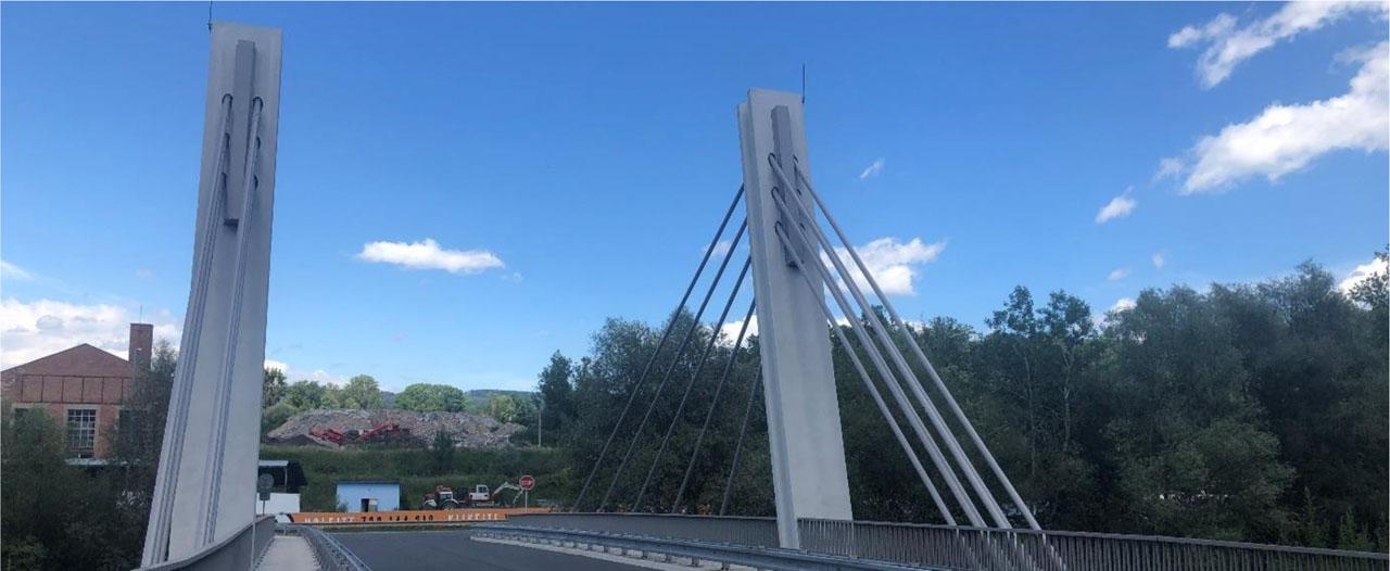
The last structure is a single-span cable-stayed bridge, 50 meters in length, crossing road II/416 over the permanent watercourse of the Svratka River (Figure 3). The bridge deck is composed of prefabricated, prestressed segments (modified KA-girders, like those used in the first structure near Hrachovec), supported by a pair of prestressed T-beams. These are suspended by stayes from a pair of inclined composite pylons made of steel and concrete, each 23 meters tall. The main girders are rigidly connected to the abutments. The rear anchor stayes are fixed to an anchorage chamber located in a shaft beneath the sidewalks. The bridge was completed in 1993, based on a design by the engineering office Dopravoprojekt Brno.

Cable-stayed bridge over the Svratka River in Židlochovice
The diagnostic inspection of stayes in cable-stayed bridges is a systematic process aimed at evaluating the condition and functionality of the load-transferring components — such as stays, stay cable anchorages, anchorage stayes, and other connecting elements that transmit forces between the bridge deck and the pylons.
In the Czech Republic in the 1990s, stayes were usually made from prestressing strands grouted inside a protective steel pipe. The deck-side anchorages were in anchorage recesses within the parapet beams, while the pylon-side anchorages were set into welded steel tubes integrated into a rigid steel assembly. Amplitude dampers were installed at both ends of each stayes to reduce stresses from random dynamic loads. In addition, a transverse vibration damper was installed at the lower anchorage to mitigate stresses caused by local bending. Stayes were designed with adjustable length to allow tension adjustment and could be replaced entirely if required.
Basic diagnostics of stayes typically include visual inspection, acoustic tracing, and semi-destructive probing, and may be supplemented by measurements of grout moisture. Extended diagnostics focus on measuring the natural frequencies dynamically and, where applicable, monitoring strain to verify the tensile forces in the stayes. The data obtained can then be used to prepare for their adjustment. These methods will be described further in the context of their application to the cable-stayed structures discussed above.
The visual inspection of stayes focuses primarily on detecting mechanical damage to the stay cable sheath, corrosion of the steel pipe or prestressing tendons, and the condition of the prestressing system anchorages. Inspection of the prestressing system anchorages involves an external visual examination of all anchorages, including those located on pylons, in the bridge deck, and in any existing anchorage chambers. For selected anchorages, the protective cover (sheath) is removed to enable inspection of the prestressing tendons. The primary focus is on verifying the integrity of the protection around the anchorage wedges provided by the covers, followed by checking whether the sheaths are filled with grease in a quantity sufficient to protect the wedges from atmospheric moisture ingress. The inspection concludes with an assessment of the overall condition of the anchorages.
This non-standard informative acoustic tracing method involves recording and evaluating the acoustic response to an impulse generated by tapping with a steel hammer weighing 1.0–2.0 kg. It is used to assess the bond between the steel tube and the grout and to detect potential voids or cavities caused by missing grout.
For the described cable-stayed bridges, both methods were carried out from an elevated work platform, with all results recorded. Acoustic tracing was then performed systematically in segments of up to 5 m along the full length of each stay cable. For shorter cables, the segments were laid out using a laser distance meter, for example, with reference to the pylon face (Figure 5a). For the longer cables on the Poděbrady bridge (Figure 5b), the procedure used vertical measuring sections, each having a maximum length of 5 m.

Stayes: a) routing of prestressing strands in a pipe, b) spacers between prestressing strands

Conducting visual inspection and acoustic tracing: a) bridge in Židlochovice with short stayes, and b) vertical measuring sections for long stayes on the bridge near Poděbrady
Assessing the condition of the prestressing reinforcement in a bridge stay cable requires selecting an appropriate location for probing, as the tendons are embedded in a grouted steel pipe. In the case of tubular cables, the most suitable probing point is usually an injection or vent port – a grouting hole (Figure 6a). Through this port, the semi-destructive probing method is performed using a suitably sized carbide drill bit. This is followed by an assessment of the condition, usually involving a single strand.

Drilled semi destructive probe in a stay cable — a) in the socket of the grouting hole, b) through the sheath
To confirm or exclude the presence of active corrosion in the prestressing tendons, a cut-out inspection opening may be made outside the grouting hole. This inspection opening, typically rectangular in shape, should be made carefully by cutting longitudinal slots in the stay cable sheath (Figure 6b). After removing the sheath, the condition of the injection mortar is visually assessed, including its moisture content, bond to the tendons, and the stay cable pipe. Once the prestressing reinforcement is exposed, its condition is evaluated with respect to corrosion processes.
In both above types of probes, the extracted injection grout may be taken for laboratory analysis, primarily to determine the pH value of the concrete surrounding the prestressing reinforcement and to diagnose what is known as chloride-induced corrosion.
After the overall evaluation of the probes, the injection grout must be replenished using a non-shrink anchoring grout, and the probe opening sealed to be watertight with a welded steel plate. Finally, the protective coating of the stay cable (PC) is restored at the probe location.
Moisture measurement of the injection grout was carried out as a supplementary method on the cable-stayed bridge over the Labe River near Poděbrady. For this purpose, the RH method was used in combination with existing ports. This approach allows determination of the relative humidity of the cementitious injection material by means of a non-destructive method.
Measuring tensile forces in stayes using frequency analysis provides a valuable extension to the diagnostic survey of cable-stayed structures. The initial measurements can serve as a reference for future stay cable adjustments. Changes in prestressing force, as well as the total tension in stayes, can be determined by analysing impulse-excited vibrations recorded with a data acquisition system and a single axis accelerometer.
For easy handling and secure attachment of the accelerometer to the outer diameter of the stayes (without damaging their surface), a simple fixture in the form of a clamp with a welded pad for sensor mounting can be used (Figure 7a). Vibrations are induced by striking the stay cable horizontally with a hammer fitted with a rubber head (Figure 6b) at a point sufficiently distant from the stay cable end (either the bridge deck surface or the arch anchorage). This method is effective for generating lower vibration modes. The recording length is typically set to at least 90 seconds. Measurements should be carried out in calm weather, with the ambient air temperature recorded, and preferably with no traffic on the bridge. In the case of uninterrupted traffic, minor interference in the recorded data may occur.

Conducting dynamic measurement: a) measuring fixture with mounted accelerometer, b) excitation by striking with a hammer fitted with a rubber head
The vibration records are then processed using frequency analysis with the FFT method. This analysis provides the natural frequencies of the stay, from which the stay cable forces can be calculated using established mathematical formulas that consider the effective vibrating length, unit mass, bending stiffness, and support flexibility.
The effective vibrating length of the stays can be determined in several ways. In the first method, the total stay cable length is reduced by the lengths of the very stiff stay cable terminations and the lower enclosed dampers (typically taken from design documentation). In the second method, the calculation is based directly on the theoretical stay cable lengths specified in the design drawings.
The method of determining forces in tensioned stayes by measuring their natural frequencies, when the effective vibrating length is correctly determined, provides reliable results for stayes of relatively greater length – typically more than 10 m. For shorter lengths, however, the choice and application of boundary-condition assumptions, as well as the actual configuration of the staye's end components, play a significant role.
Strain measurements of stay cable forces are used as a verification tool to determine the stress in the stayes and to calibrate the results of dynamic testing. Vibrating-wire sensors are temporarily installed on the stay cable surface to continuously monitor strain variations, such as during stay cable re-tensioning. The measurements confirm that a stay cable consisting of grouted strands inside a steel tube behaves as a single, integrated structural unit. Further details on stay cable strain measurement procedures are given in Nečas et al. (2021).
The diagnostic survey of the stayes was carried out for all three cable-stayed structures described in the introduction. The investigation included: a visual inspection of the external stay cable sheath surfaces with a register of defects; acoustic tracing of individual stay; opening of the sheath access ports in threaded couplings (followed by resealing); probing of the sheath outside the couplings with subsequent reinstatement; and a visual assessment of the grout condition. The survey also covered inspection of the pylon and deck anchorages, documentation of the condition of the prestressing strands within the stayes, and sampling of grout for laboratory chemical analysis. In addition, the stay cable investigations were supplemented by determining the material characteristics of the concrete in both the bridge structure and the substructure; conducting a special inspection of the bridge structure; assessing the condition of deck prestressing tendons using drilled probes (including verification of the filling of tendon ducts in the main girders and transverse deck elements); performing an expert corrosion assessment; and developing recommendations for remedial measures.
The visual inspection began with an examination of the entire length of the external stay cable sheath, which, for all inspected bridges, consisted of a steel pipe. Any damage identified was documented photographically. Common defects included abrasions, localized thinning of the coating, and corrosion, particularly at the welded joints of the steel pipes (Figure 8a). In these areas, where the base material of the stay cable sheath had been chemically altered by the welding process, the protective coating had reached the end of its service life, resulting in progressive corrosion and flaking of the topcoat. Additional issues observed included areas with incomplete coating, dents, bends, and contamination, most of which likely originated during the construction phase.

Results of visual inspection: a) corrosion of external sheath joints, b) corrosion damage to the protective coating system of the anchorage and missing anchorage cover
During the diagnostic investigations, a visual inspection of all stay cable anchorages was carried out. In most cases, corrosion of the surface protective coating (topcoat) was visible, and in some instances, flaking was also observed (Figure 8b). These findings were consistent regardless of whether the anchorages were located beneath the bridge deck or in anchorage chambers — as with the bridges in Židlochovice and near the village of Hrachovec — or inside the bridge box girder, as in the case of the Poděbrady bridge. Wherever rainwater could penetrate — for example, due to failed deck waterproofing or water ingress between the steel pipe and the protective sleeve at the deck penetration — the protective coating on the anchorages had deteriorated.
For anchorages located inside chambers (Figure 9b), although sheltered from direct weathering, significant water intrusion evidently occurred during rain events. These chambers lacked both ventilation and accessible inspection openings, which significantly accelerated the corrosion process. The damage affected not only the anchorage housings but also the adjustment nuts and washers.

Condition of anchorages: a) on the pylon, b) in the anchorage chamber of the bridge over the Svratka River in Židlochovice
The condition of the pylon anchorages varied slightly depending on their exposure to the outdoor environment. At the bridges in Židlochovice (Figure 9a) and near Hrachovec, the anchorages were exposed to weathering, whereas at the Poděbrady bridge they were located inside the pylon, where they were better protected.
No signs of moisture, water leakage, or corrosion were detected in the anchorages located inside the pylons. For the external pylon anchorages, only slight or no surface corrosion was observed, with occasional localized damage to the protective coating.
For selected stay cable anchorages, the protective cover was removed. None of the inspected anchorages showed any indications of moisture, water leakage, or corrosion of the prestressing strands. However, in several anchorages, an insufficient amount of lubricant was found on the anchorage wedges, which protect them against the ingress of atmospheric moisture (Figure 10).

Example of lubricant condition after removing the protective cover: a) in the anchorage chamber, b) on the pylon
Acoustic tracing of the grouting in all stays primarily revealed areas with a resonant or hollow response, indicating potential voids or cavities. These defects were detected mainly on the Poděbrady bridge, in the upper sections of the stays near the pylons (red section in Figure 11). The most likely cause was settlement of the grouting compound, leading to the formation of cavities, particularly beneath the anchorages. No such cavities were found on the bridges in Židlochovice and near Hrachovec; however, it should be noted that on these bridges the area directly beneath the anchorage—where grout settlement could occur—is located inside the pylon (Figure 9a).

Condition of grouting for half of harp P3 with stays on the left side of the bridge over the Elbe River near Poděbrady
The results of the acoustic tracing and visual inspection were evaluated graphically for each stay cable individually and then compiled into an overall assessment for each stay cable harp (see example in Figure 11).
During the inspection of each bridge, selected stayes were subjected to semi-destructive testing, involving probes inserted through the grout inlet sleeves and, in some cases, directly through the steel pipe casing of the stay cable.
A visual inspection of these probes confirmed that all probes located in the grouting ports at the lower ends of the stayes contained grout that provided protective passivation of the prestressing strands. After drilling and exposing the prestressing reinforcement, the strands were found to be intact (Figure 6).
In-situ pH testing using a Rainbow indicator (Figure 12a) and laboratory analysis confirmed that the pH values of the grout were consistently high (greater than 12.00). Such a strongly alkaline environment ensures that the grout effectively maintains the passivation of the prestressing strands.

Cut through probe through the stay cable sheath on the bridge in Židlochovice: a) indicative pH test, b) sealing with a welded steel patch
Samples of the tendon injection grout were also subjected to laboratory analyses to determine the chloride content. The chloride concentration is a critical durability parameter, as values exceeding 0.6% are generally recognized as a threshold beyond which the risk of reinforcement corrosion significantly increases. In all analyzed samples, only trace concentrations of chlorides were identified, confirming that the grout ensures adequate protection of the prestressing tendons against corrosion.
Finally, the cut inspection ports were reinstated by filling them with Groutex Fill In, a thixotropic, non-shrink structural repair grout, and resealing them with the original steel cover plate, hermetically welded along the entire perimeter (Figure 12b). The surrounding surface was subsequently overcoated with a protective anti-corrosion coating system to ensure long-term structural durability.
Dynamic measurements of the natural frequencies of the bridge stayes, followed by the calculation of axial forces, were carried out for the cable-stayed bridges near Hrachovec and Židlochovice.
For the Hrachovec bridge, vibration measurements were performed in August and November 2019. The August campaign was conducted primarily for calibration purposes — to fine-tune the analytical model used to determine stay cable axial tension from measured natural vibration frequencies. This was achieved by computing the frequency spectra of the recorded vibrations and subsequently deriving the tensile forces using established analytical formulations for prestressed, axially restrained members (Geier, De Roeck, & Pety, 2005; Nečas, 2010).
The November measurements aimed to establish baseline force values in the stayes after completion of the bridge repair and to prepare for possible long-term, repeated monitoring of the bridge. For calibration, only a subset of stayes was instrumented, in coordination with site operations. Dynamic response measurements during stay cable re-tensioning were carried out in accordance with a predefined sequence. Initially, axial forces in the stay cable were recorded in the as-found condition (prior to tensioning). Subsequent measurements were taken during the re-tensioning process at the point when the original axial force had been neutralised (anchor released, with a small gap formed between the anchorage and the bearing plate). Additional measurements were performed after re-tensioning to the specified design force, during slight over-tensioning prior to final anchoring, and finally after completion of anchoring and release of the hydraulic jack (Table 1).
Calibration tensioning of stay cable Z45L on the bridge near the village of Hrachovec
| Calibration of stay cable tension Z45L | Measured frequency f [Hz] | Stay cable force FV [kN] | Stay cable force according to NAPKO FN [kN] | Comparison [%] |
|---|---|---|---|---|
| Initial condition before rectification | 5.20 | 920 | ||
| Anchor release | 5.34 | 979 | 968 | 101% |
| Required tension | 6.57 | 1567 | 1622 | 97% |
| Overtension before anchoring | 6.81 | 1697 | 1732 | 98% |
| Re-anchoring | x | x |
As part of the diagnostic survey of the Židlochovice bridge, baseline dynamic frequency measurements were taken using an accelerometer sequentially mounted on each stay cable (Figure 7a). These measurements provided the fundamental natural frequency of each stay cable, from which indicative axial forces were subsequently derived.
Comparing the measured natural frequencies made it possible to assess relative differences in axial tension between stayes of the same nominal length, as well as to identify any asymmetry in forces between the right and left sides of the structure (Figure 13). This measurement was not intended to identify the causes of unequal axial forces but to provide a basis for planning stay rectification during the subsequent repair of the bridge. Possible sources of force differences include construction procedures, stressing equipment, sequential tensioning of stays during cantilever construction, prestress losses or rheological effects.

Comparison of the first natural frequencies of stayes in the main span (orange – left stayes, blue – right stayes, green – expected trend)
Figure 13 also shows noticeable deviations from the expected trend, indicated by the dashed green line. The first stay cable on the right side exhibits a slightly higher natural frequency, corresponding to an increased axial force. On the left side (orange plot in Figure 13), the two longest stayes deviate from the general trend, showing a marked reduction in frequency and, consequently, a lower axial force.
The axial forces in the stayes were determined from the fundamental natural frequency, calculated for the effective stay cable length (excluding the lower dampers), using analytical relations for fixed-end stranded members. The reliability of the calculated forces depends on proper calibration of the dynamic measurement, verified, for example, during rectification using a hydraulic tensioning press (as carried out on the bridge near Hrachovec). The obtained forces can then be compared with those derived from the structural static analysis. If discrepancies are found, the force–frequency correlation can be refined by adjusting the effective vibration length or by applying alternative boundary conditions at the supports.
Strain-gauge measurements of the stayes were carried out only on the bridge near Hrachovec and served as a verification method for the dynamic analysis. A closed-loop strain-monitoring system was installed to record variations in strain and stress in the stayes. The instrumentation consisted of surface-mounted vibrating-wire strain gauges with weldable end blocks (Figure 14a).

Strain-gauge measurement: a) installed vibrating-wire strain gauge, b) deformation and temperature record from a selected gauge
While strain gauging alone cannot determine the initial prestress level or the absolute axial force in the stay cable, it allows continuous monitoring of tension changes, making it possible to detect any increase or decrease in axial force during the measurement period (Figure 14b).
In this paper, selected methods for the diagnostics of stayes and the subsequent determination of axial forces in the stayes of three cable-stayed bridges have been presented. The diagnostic investigations proved instrumental in planning and executing repairs, while also demonstrating the potential to enhance diagnostic practices through the application of advanced techniques and newly developed methodologies.
The visual inspection identified the need for a complete renewal of the anti corrosion coating on all stay cable sheaths. Remedial works should include refurbishment of exposed anchor surfaces and restoration of corrosion protection systems (PC) for anchorages on pylons, within anchorage chambers, and in the bridge deck — including protective covers, nuts, and washers. In addition, it was recommended to redesign the protective covers to allow for pressure-injection replenishment of lubricants containing corrosion inhibitors.
The elastomeric sleeves (vibration dampers) should be disassembled, the internal lubricant inspected and replenished, and the stay cable entry points resealed. All grouting and venting ports should be inspected and properly sealed. Where air voids are detected, they should be filled with non-shrink repair grout, and threaded end caps should be hermetically sealed to prevent ingress of moisture and aggressive agents.
Acoustic testing revealed the presence of voids and cavities in the upper regions of the stayes. Targeted re-grouting should therefore be planned at these locations, ideally after removing anchor protection casings or exposing the ducts beneath the anchorages.
Semi-destructive investigative probes confirmed that the prestressing tendons are sufficiently protected by the stay cable system described in the introduction to Chapter 2.
Dynamic measurement can be effectively applied in the future thanks to its simplicity. Mounting an accelerometer on a stay cable requires no intervention in the cable-stayed structure, and measurements can be performed under normal bridge operation. The key prerequisite is to establish the initial condition (forces in individual stayes) through proper calibration of the measuring system. Once calibrated, accelerometers can then be used to detect changes in stay cable forces, for example, due to rheological effects.
Calibration of the dynamic method on the Hrachovec bridge was carried out by comparing the forces recorded by the hydraulic tensioning jack during re-tensioning with those obtained from strain-gauge measurements on selected stayes. In this case, the calibration results showed very good agreement between the two methods.
The method of determining forces in tensioned stayes by measuring their natural frequencies provides reliable results for stayes with relatively long lengths (approximately > 16–20 m). For shorter stayes, the assumed boundary conditions and the actual detailing of the stay cable ends have a much greater influence and must be carefully considered in the analysis.