
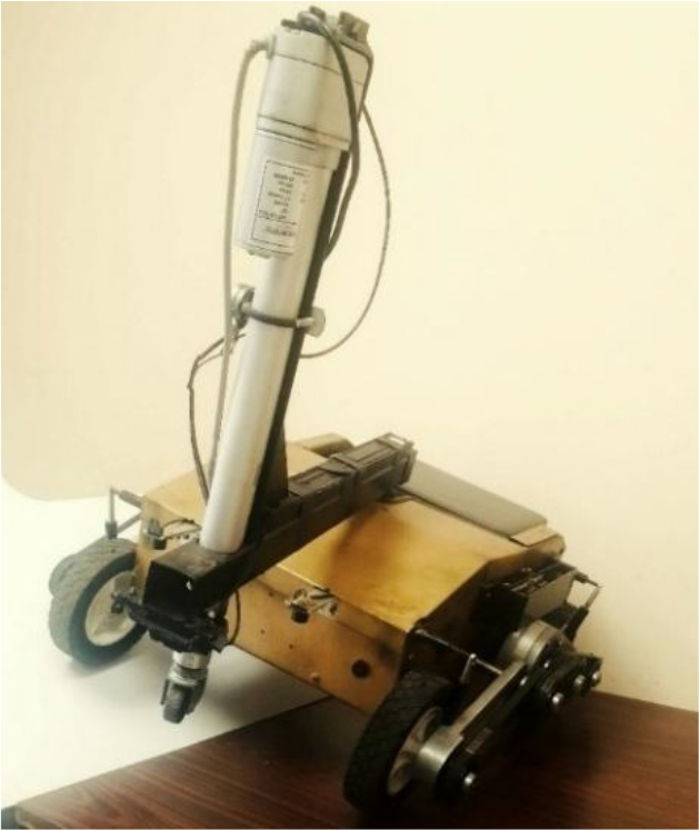
Fig. 1.
Lázaro robot
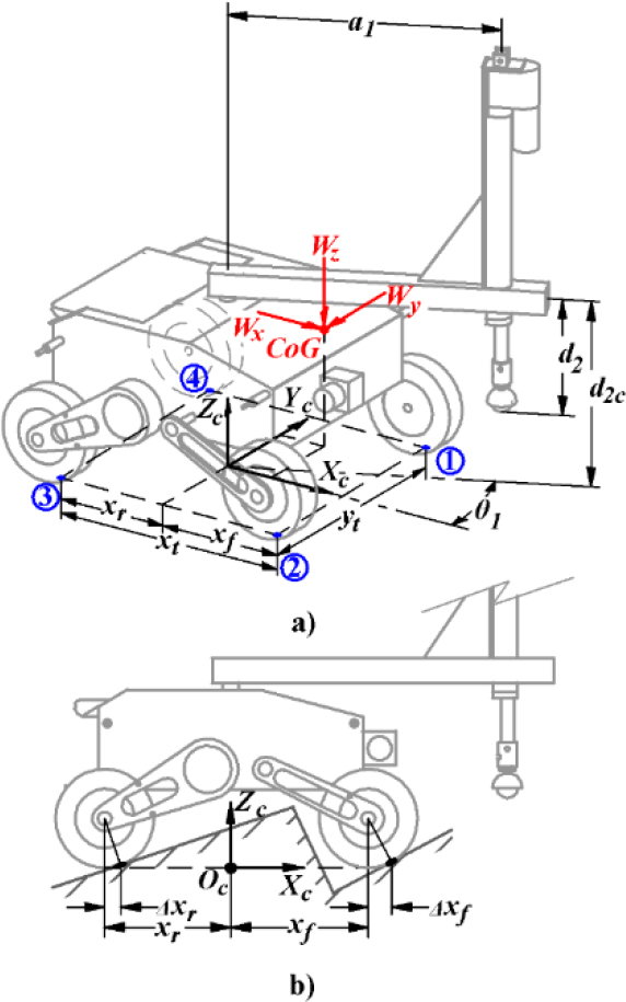
Fig. 2.
Lázaro robot showing dimensions and Xc Yc Zc frame a) Axono metric view; b) Side view
Tab. 1.
Dimensional parameters of Lázaro robot
| Parameter | Magnitude |
|---|---|
| xf | 209.0 mm |
| xr | 191.0 mm |
| xt | 400.0 mm |
| yt | 398.0 mm |
| a1 | 420.0 mm |
| d2c | -282.5 mm |
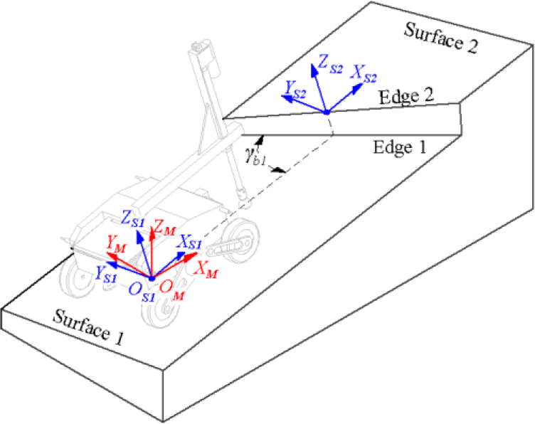
Fig. 3.
Geometric parameters used to characterize the obstacle
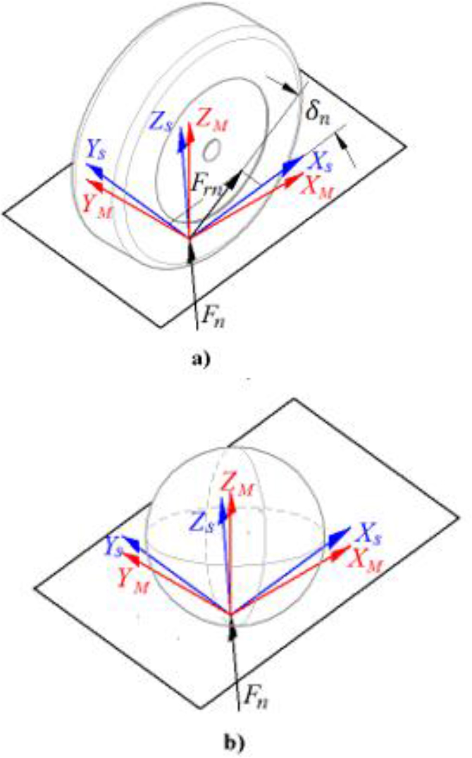
Fig. 4.
Forces at the wheel-ground contact point: a) robot wheel; b) wheel at the end effector
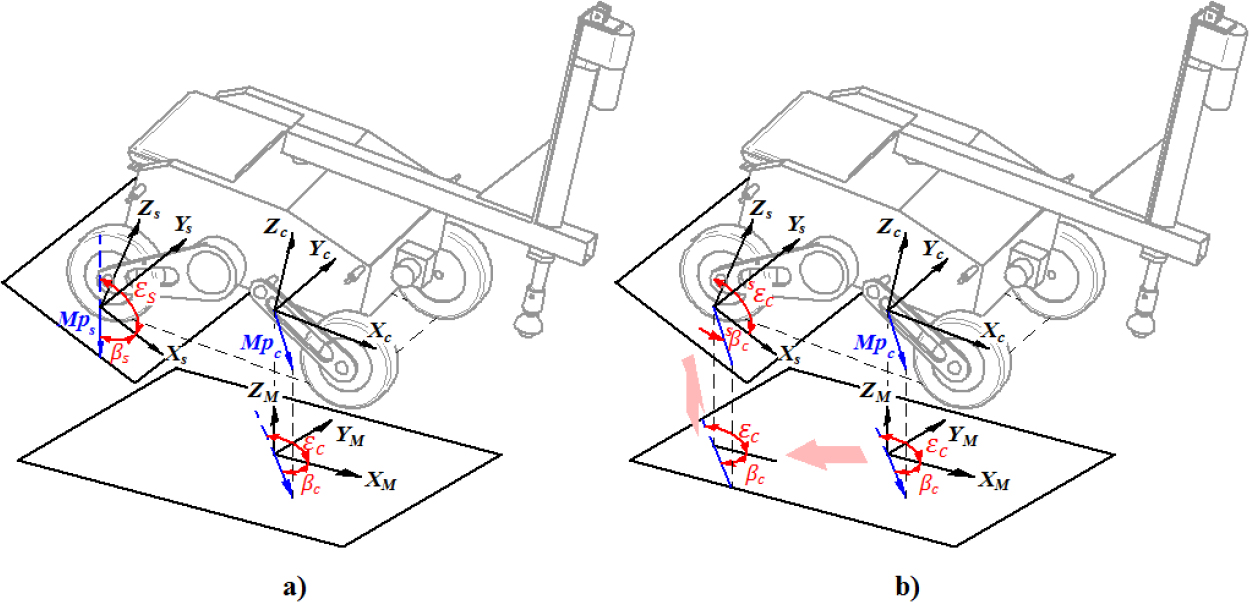
Fig. 5.
Direct angles of the maximum slope on Surface s and on the XC YC plane
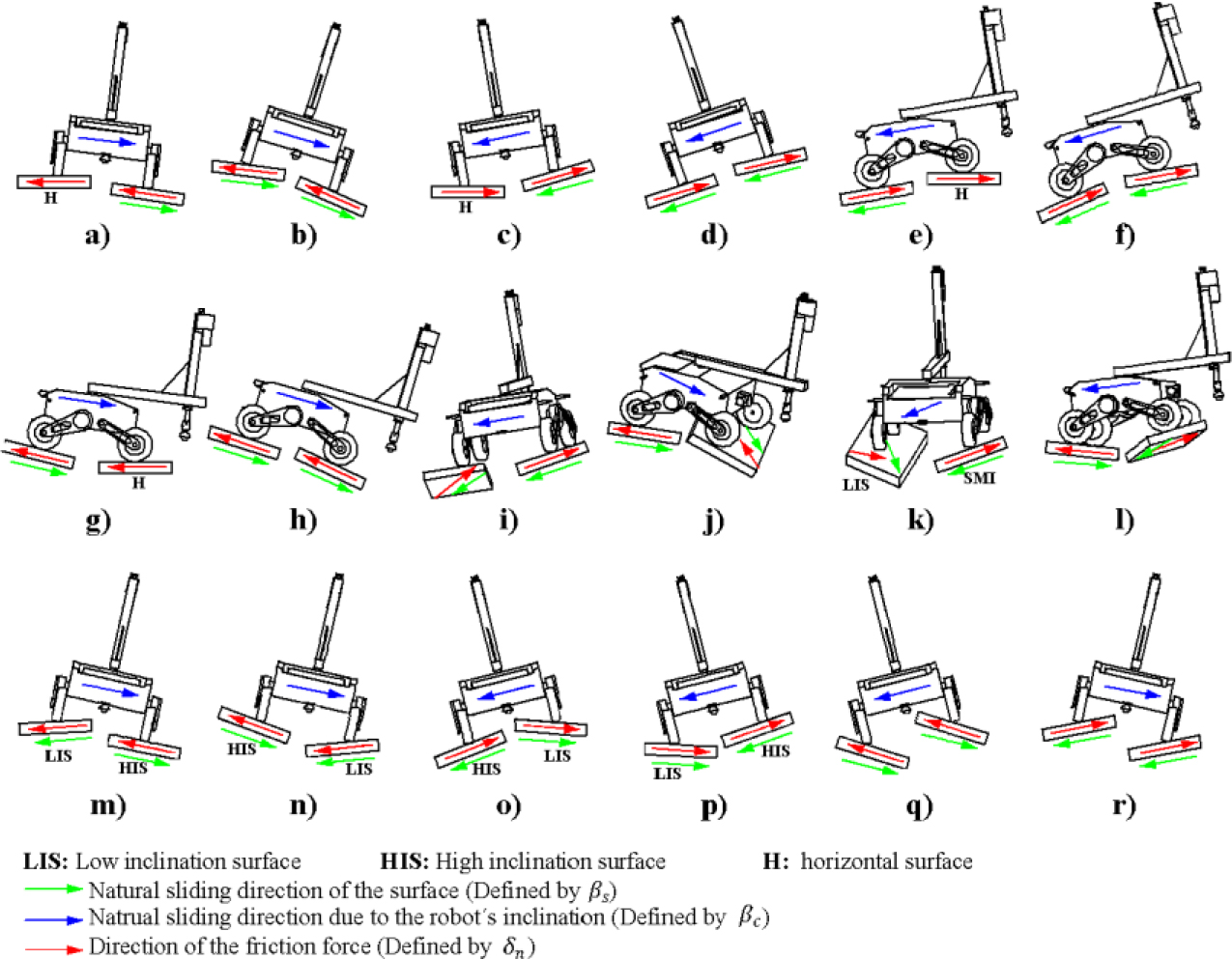
Fig. 6.
Results of simulations to estimate δn
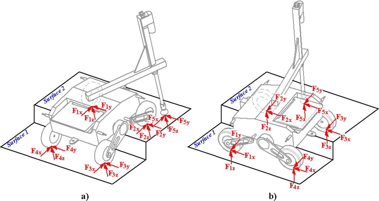
Fig. 7.
Robot overcoming obstacle with two wheels on each surface
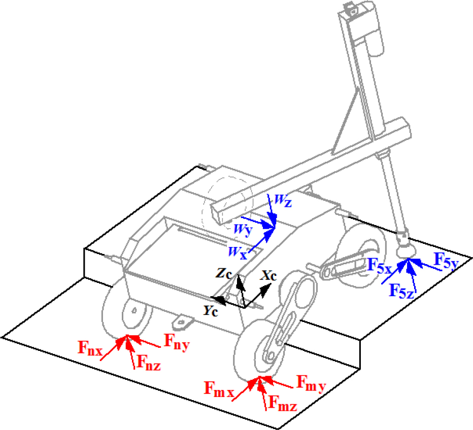
Fig. 8.
Robot overcoming obstacle supported by 2 wheels and the end effector

Fig. 9.
Simulations to validate Is with the robot touching the ground with 4 wheels
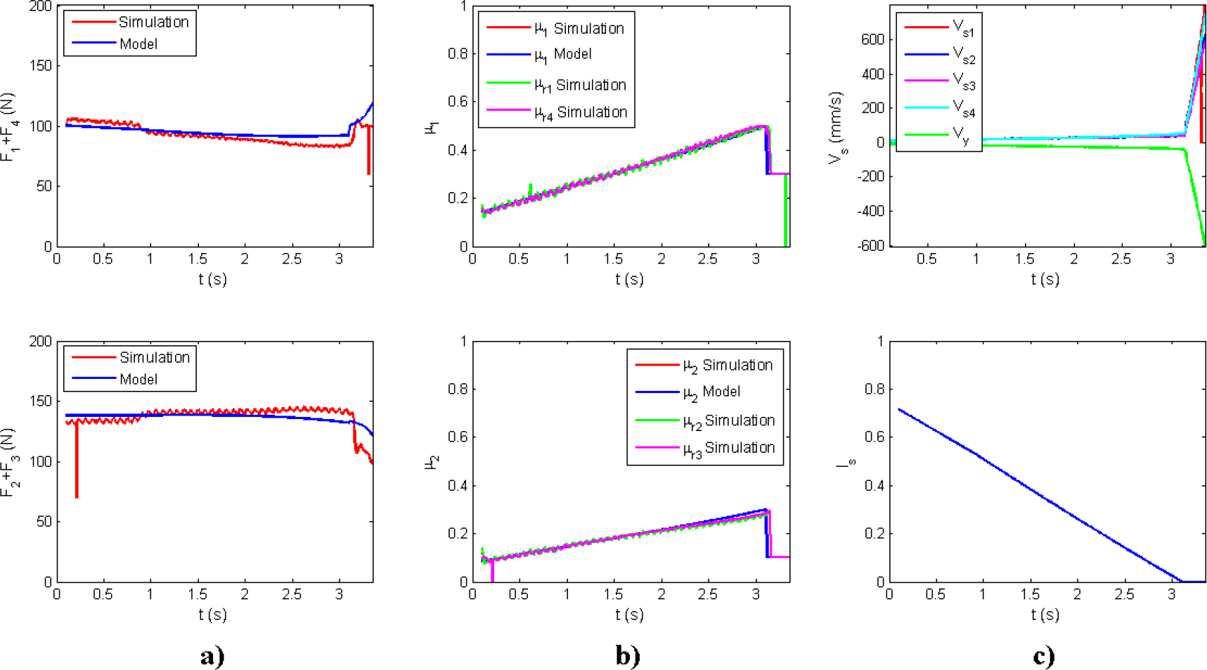
Fig. 10.
Results corresponding to Test "a" (Fig. 9) with F5z=0 N
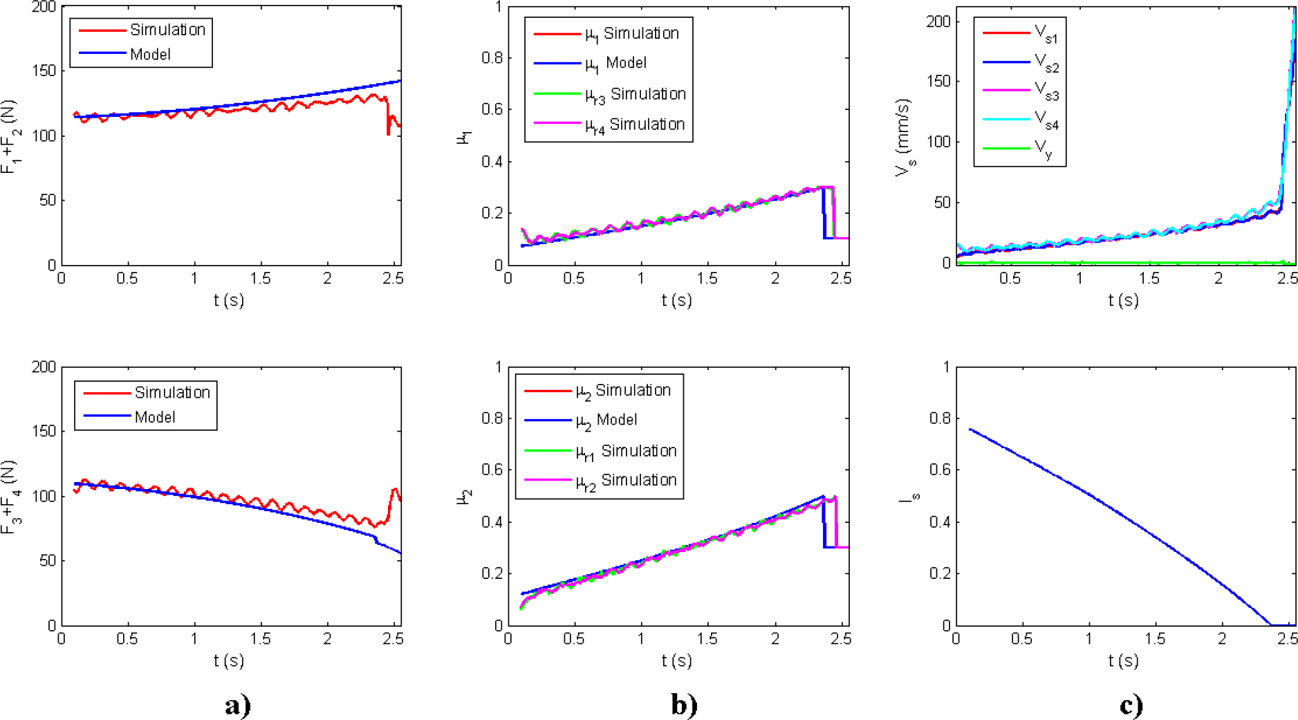
Fig. 11.
Results corresponding to Test "d" (Fig. 9) with F5z=15 N
Tab. 2.
Statistical analysis of simulation results to validate Is Test
| Test | F5 (N) | Fs1 | Fs2 | μ1 | μ2 | ||||||||
|---|---|---|---|---|---|---|---|---|---|---|---|---|---|
| σ (N) | MAPE (%) | σ (N) | MAPE (%) | σ | MAPE (%) | σ | MAPE (%) | ||||||
| a | 0 | -2.01 | 4.61 | 1.99 | 1.68 | 6.22 | 1.19 | 0.00 | 0.01 | 0.80 | -0.01 | 0.01 | 3.42 |
| 15 | -1.98 | 4.47 | 2.13 | 1.90 | 4.71 | 1.43 | 0.00 | 0.01 | 1.57 | 0.00 | 0.01 | 2.32 | |
| 30 | -2.04 | 4.57 | 2.41 | 2.00 | 4.45 | 1.60 | 0.02 | 0.01 | 5.83 | 0.00 | 0.01 | 0.72 | |
| 45 | -1.38 | 4.54 | 1.79 | 1.18 | 5.00 | 1.03 | 0.05 | 0.01 | 17.25 | 0.01 | 0.05 | 0.24 | |
| b | 0 | 1.45 | 4.52 | 1.00 | -1.95 | 4.63 | 2.02 | 0.00 | 0.00 | 0.41 | 0.00 | 0.01 | 1.08 |
| 15 | 0.27 | 5.33 | 0.15 | -0.66 | 5.79 | 0.75 | 0.00 | 0.03 | 2.25 | 0.00 | 0.04 | 4.53 | |
| 30 | -1.75 | 5.52 | 1.47 | 1.45 | 6.11 | 1.73 | 0.00 | 0.03 | 0.37 | -0.01 | 0.06 | 9.85 | |
| 45 | -2.08 | 4.20 | 1.85 | 1.74 | 4.13 | 2.39 | 0.02 | 0.02 | 8.24 | 0.01 | 0.04 | 5.80 | |
| c | 0 | -7.54 | 7.56 | 5.16 | 7.09 | 6.31 | 7.50 | 0.00 | 0.04 | 2.27 | -0.02 | 0.03 | 8.75 |
| 15 | -8.01 | 8.75 | 5.22 | 7.21 | 6.00 | 10.13 | -0.01 | 0.05 | 3.21 | -0.03 | 0.04 | 9.89 | |
| 30 | -7.30 | 8.07 | 4.57 | 6.63 | 6.09 | 13.01 | -0.01 | 0.05 | 6.60 | -0.03 | 0.05 | 9.99 | |
| d | 0 | 4.16 | 3.46 | 4.31 | -4.47 | 2.88 | 3.10 | 0.01 | 0.01 | 3.56 | -0.01 | 0.01 | 3.69 |
| 15 | 3.80 | 3.61 | 3.61 | -4.24 | 2.98 | 3.53 | 0.01 | 0.01 | 2.80 | -0.01 | 0.01 | 3.72 | |
| 30 | 3.47 | 3.80 | 2.99 | -4.03 | 3.90 | 4.25 | 0.01 | 0.01 | 2.15 | -0.01 | 0.01 | 3.53 | |
| 45 | 3.35 | 4.25 | 2.71 | -4.04 | 5.14 | 5.80 | 0.00 | 0.01 | 1.22 | -0.01 | 0.01 | 3.93 | |
| e | 0 | -9.04 | 1.77 | 6.01 | 8.61 | 1.94 | 10.52 | -0.01 | 0.02 | 4.50 | 0.05 | 0.01 | 5.44 |
| 15 | -9.13 | 1.78 | 6.44 | 9.03 | 1.50 | 11.73 | -0.01 | 0.01 | 3.82 | 0.05 | 0.01 | 8.88 | |
| 30 | -7.57 | 7.62 | 5.88 | 7.48 | 4.07 | 9.86 | -0.02 | 0.06 | 24.78 | 0.04 | 0.01 | 15.52 | |
| 45 | -8.15 | 2.08 | 6.77 | 8.14 | 2.58 | 11.61 | 0.00 | 0.01 | 0.45 | 0.04 | 0.06 | 17.69 | |
| f | 0 | 3.35 | 4.66 | 3.24 | -3.90 | 4.21 | 2.82 | 0.02 | 0.01 | 15.82 | -0.02 | 0.03 | 6.28 |
| 15 | 3.99 | 6.81 | 3.49 | -4.48 | 6.66 | 3.95 | 0.02 | 0.01 | 14.91 | -0.02 | 0.06 | 8.35 | |
| 30 | 1.32 | 5.69 | 0.99 | -2.29 | 6.58 | 2.75 | -0.02 | 0.04 | 12.12 | -0.02 | 0.02 | 8.81 | |
| 45 | 0.77 | 5.85 | 0.53 | -1.71 | 5.75 | 2.76 | -0.02 | 0.03 | 10.13 | -0.02 | 0.03 | 7.65 | |
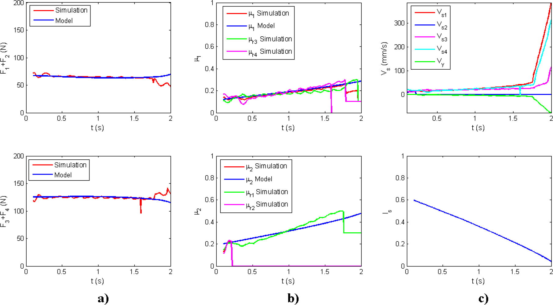
Fig. 12.
Results corresponding to Test "f" (Fig. 9) with F5z=45 N

Fig. 13.
Simulations to validate Is with the robot touching the ground at three points
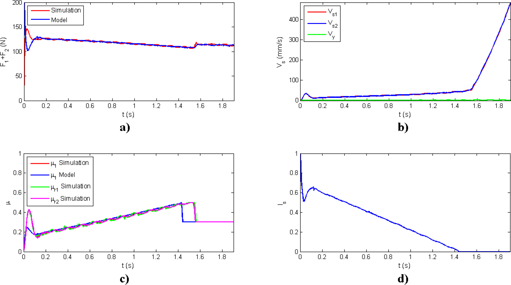
Fig. 14.
Results corresponding to Test "b" (see Fig. 13)
Tab. 3.
Statistical analysis of the simulations when the robot touches the ground at 3 points
| Test | Fs1 | Fs2 | μ1 | μ2 | ||||||||
|---|---|---|---|---|---|---|---|---|---|---|---|---|
| σ (N) | MAPE (%) | σ (N) | MAPE (%) | σ | MAPE (%) | σ | MAPE (%) | |||||
| a | 0.15 | 4.10 | 0.06 | - | - | - | 0.01 | 0.04 | 0.98 | - | - | - |
| b | - | - | - | 0.21 | 1.53 | 0.17 | - | - | - | 0.01 | 0.05 | 1.53 |
| c | -0.21 | 1.20 | 0.16 | - | - | - | 0.01 | 0.04 | 0.13 | - | - | - |
| d | - | - | - | -0.20 | 1.23 | 0.15 | - | - | - | 0.00 | 0.04 | 0.84 |
| e | 0.03 | 2.10 | 0.02 | - | - | - | 0.00 | 0.04 | 0.46 | - | - | - |
| f | - | - | - | -0.58 | 1.84 | 0.44 | - | - | - | 0.01 | 0.05 | 1.67 |
Tab. 4.
Geometry of obstacles and static friction coefficients used
| Simulation | Description | ϕs1 (°) | αs1 (°) | ϕs2 (°) | αs2 (°) | γb1 (°) | μs1 | μs2 |
|---|---|---|---|---|---|---|---|---|
| A | Frontal ascent | -5.00 | 0.00 | -9.67 | -2.58 | 74.94 | 1.0 | 0.2 |
| B | Lateral descent | 7.71 | 0.00 | 7.50 | -4.33 | 150.22 | 0.4 | 0.4 |
| C | Lateral trench | 0.00 | 10.00 | 0.00 | 10.00 | 25.34 | 0.4 | 0.4 |
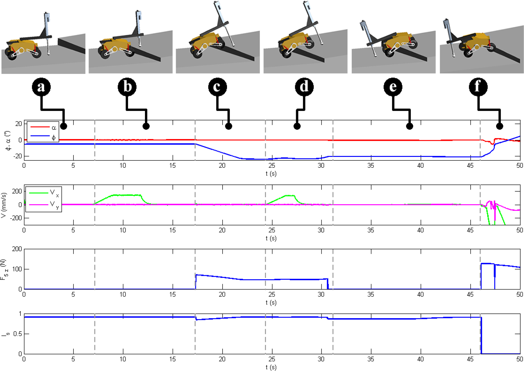
Fig. 15.
Analysis of stages for overcoming obstacles until slipping (Simulation A)
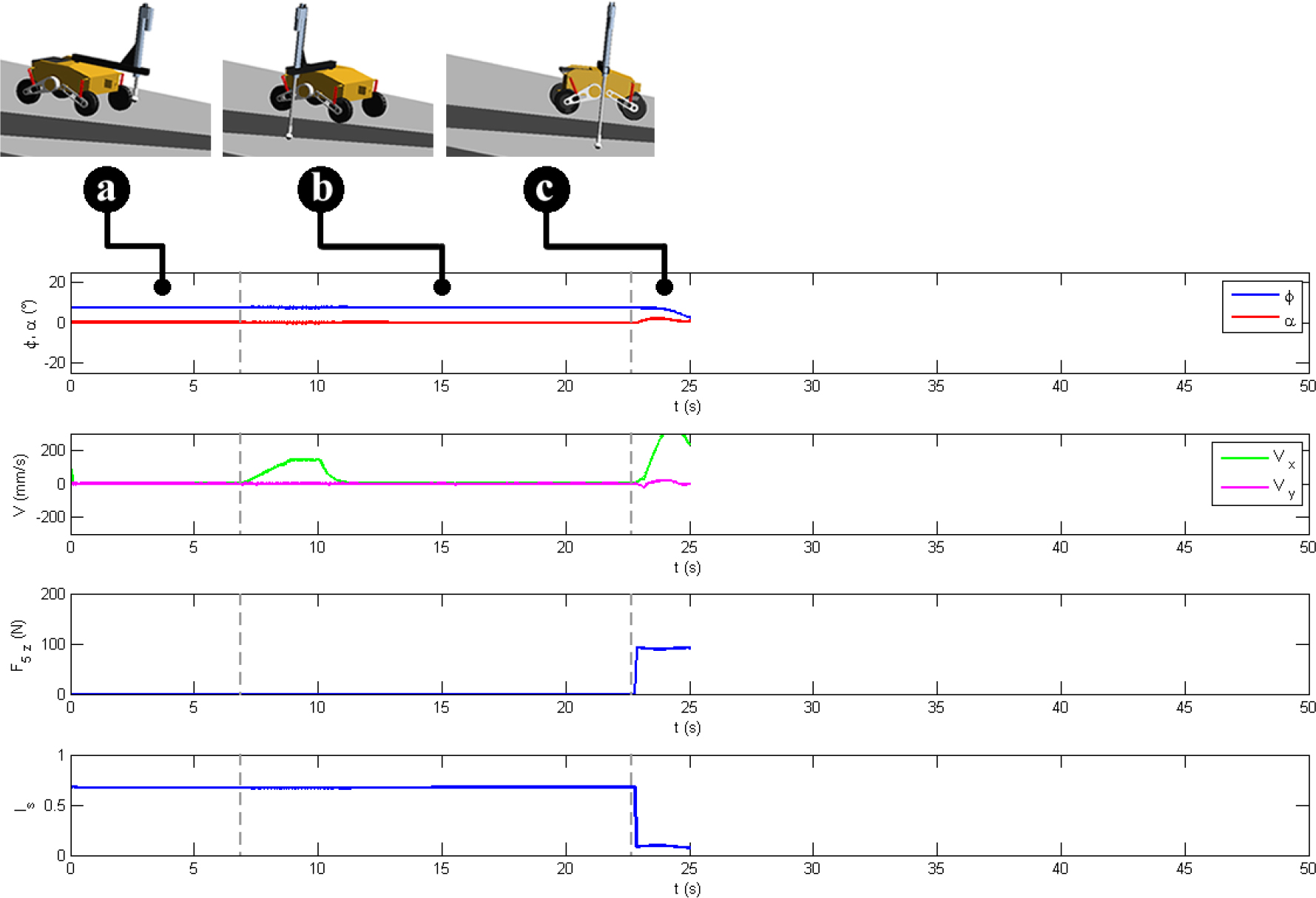
Fig. 16.
Analysis of stages for overcoming obstacles until slipping (Simulation B)
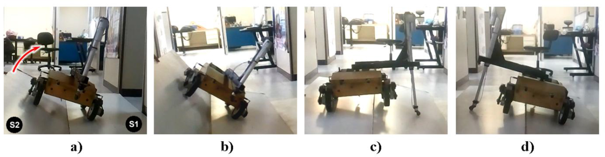
Fig. 17.
Tests conducted with the Lázaro robot to validate Is
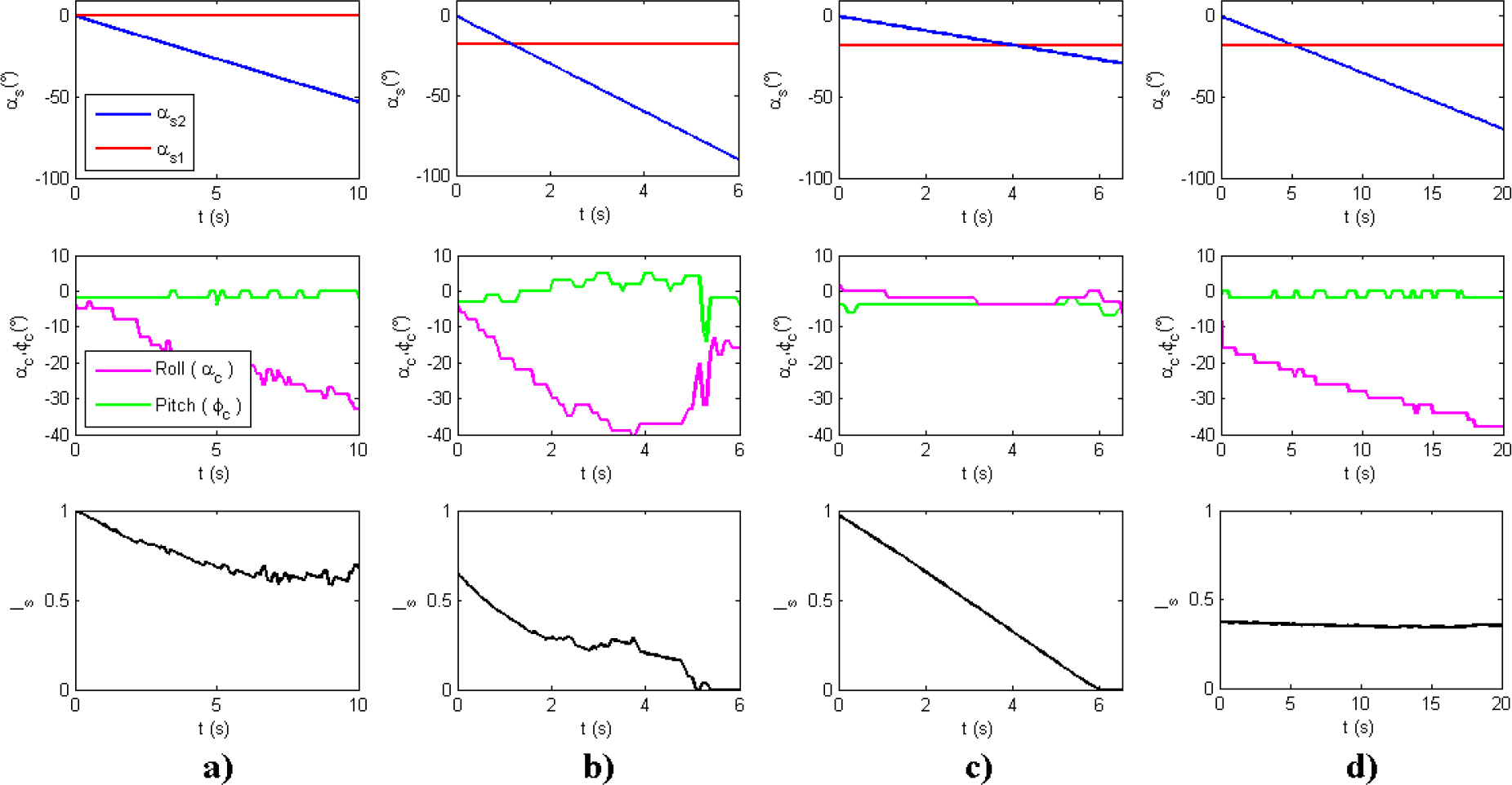
Fig. 18.
Results of the tests conducted with the Lázaro robot to validate Is