
Tab. 1.
The following table summarizes all the potential solutions to equation (2.3) for the specific m2, m1, and m0 values that have been provided
| NO. | m2 | m1 | m0 | N |
|---|---|---|---|---|
| 1 | k2 | –(1 + k2) | 1 | sn |
| 2 | k2 | –(1 + k2) | 1 | cd |
| 3 | –k2 | 2k2 – 1 | 1 – k2 | cn |
| 4 | –1 | 2 – k2 | k2 – 1 | dn |
| 5 | 1 | –(1 + k2) | k2 | ns |
| 6 | 1 | –(1 + k2) | k2 | dc |
| 7 | 1 – k2 | 2k2 – 1 | –k2 | nc |
| 8 | k2 – 1 | 2 – k2 | –1 | nd |
| 9 | 1 – k2 | 2 – k2 | 1 | sc |
| 10 | –k2(1 – k2) | 2k2 – 1 | 1 | sd |
| 11 | 1 | 2 – k2 | 1 – k2 | cs |
| 12 | 1 | 2k2 – 1 | -k2(1 – k2) | ds |
| 13 | kcn ∓ dn | |||
| 14 | ns ∓ cs | |||
| 15 | nc ∓ sc | |||
| 16 | ns ∓ ds | |||
| 17 | sc ∓ icn | |||
| 18 | ||||
| 19 | kcn ∓ idn | |||
| 20 | ||||
| 21 | ||||
| 22 | ||||
| 23 | ||||
| 24 | ||||
| 25 |
Tab. 2.
The Jacobi elliptic function exhibit specific limiting behaviour as k → 0 and k → 1
| No. | Function | k → 1 | k → 0 |
|---|---|---|---|
| 1 | sn(v) | tanh(v) | sin(v) |
| 2 | cn(v) | sech(v) | cos(v) |
| 3 | dn(v) | sech(v) | 1 |
| 4 | cd(v) | 1 | cos(v) |
| 5 | sd(v) | sinh(v) | sin(v) |
| 6 | nd(v) | cosh(v) | 1 |
| 7 | dc(v) | 1 | sec(v) |
| 8 | nc(v) | cosh(v) | sec(v) |
| 9 | sc(v) | sinh(v) | tan(v) |
| 10 | ns(v) | coth(v) | csc(v) |
| 11 | ds(v) | csch(v) | csc(v) |
| 12 | cs(v) | csch(v) | ct(v) |
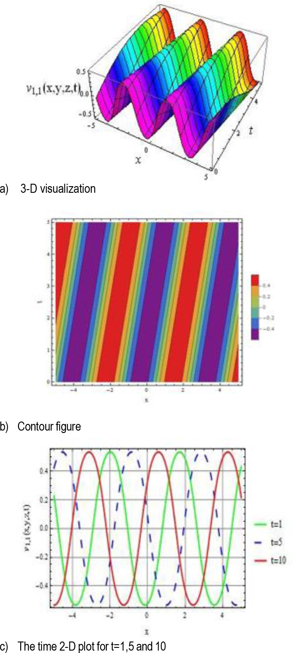
Fig. 1.
The 3-D visualization, contour plot, and 2-D graphical representation of V1,1(x, y, z) are presented for the parameter values k = 0.5, r = 1, p = 2, q = –2, and y = z = 1
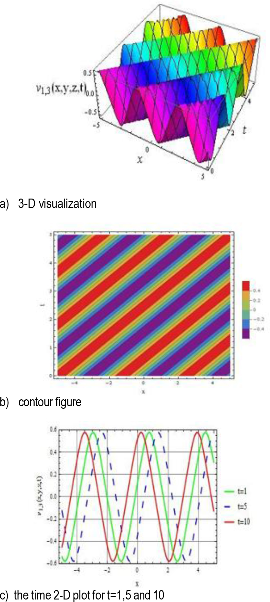
Fig. 2.
The 3-D visualization, contour plot, and 2-D graphical representation of v1,3(x, y, z) are presented for the parameter values k = 0.5, r = 0.5, p = 2, q = 2, and y = z = 1
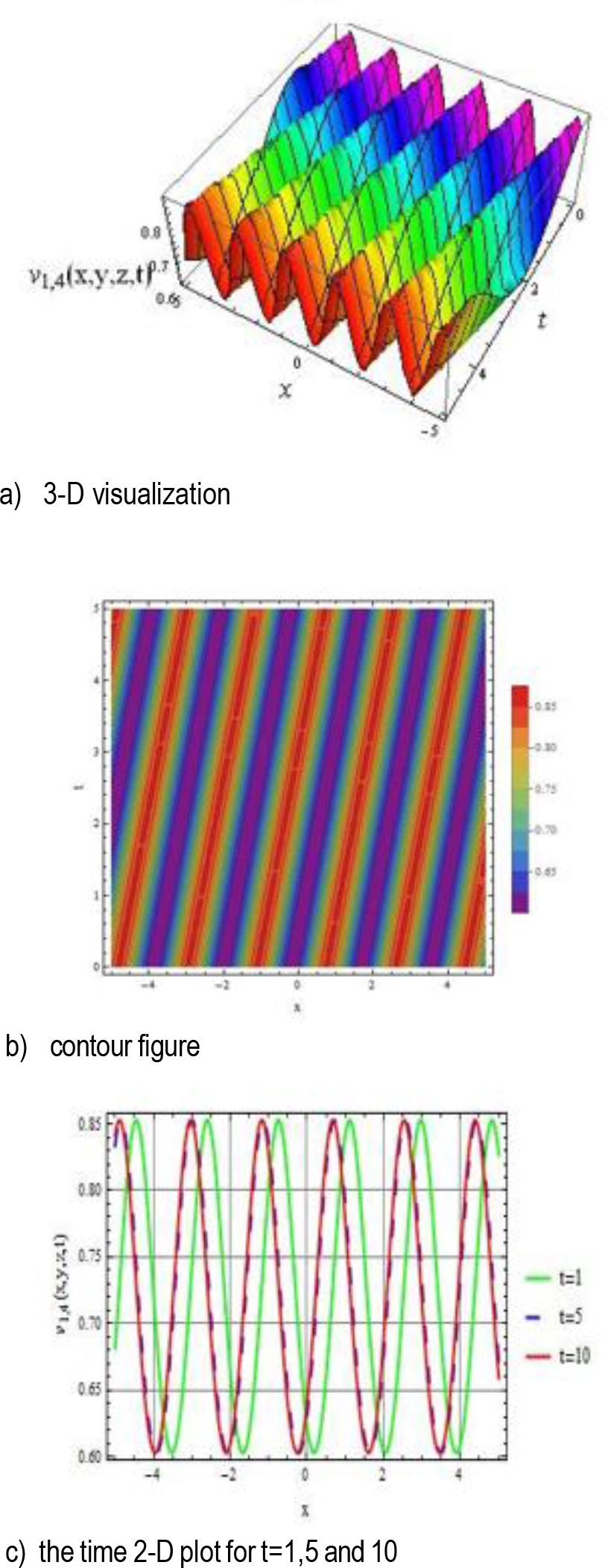
Fig. 3.
The 3-D visualization, contour plot, and 2-D graphical representation of V1,4(x, y, z) are presen-ted for the parameter valuesk = 0.5, r = 0.5, p = 2, q = –2, and y = z = 1
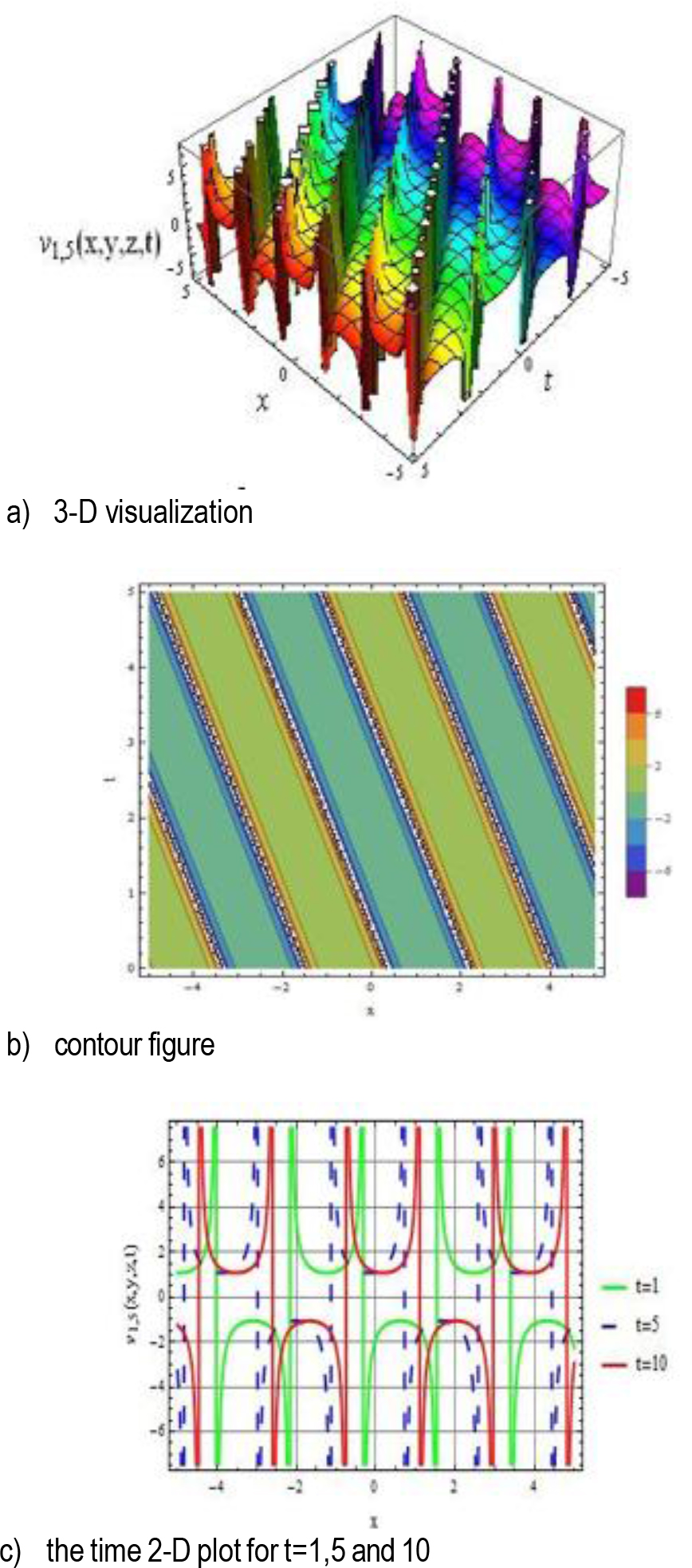
Fig. 4.
The 3-D visualization, contour plot, and 2-D graphical representation of V1,5(x, y, z) are presen-ted for the parameter values k = 0.5, r = 1, p = 2, q = 2, and y = z = 1
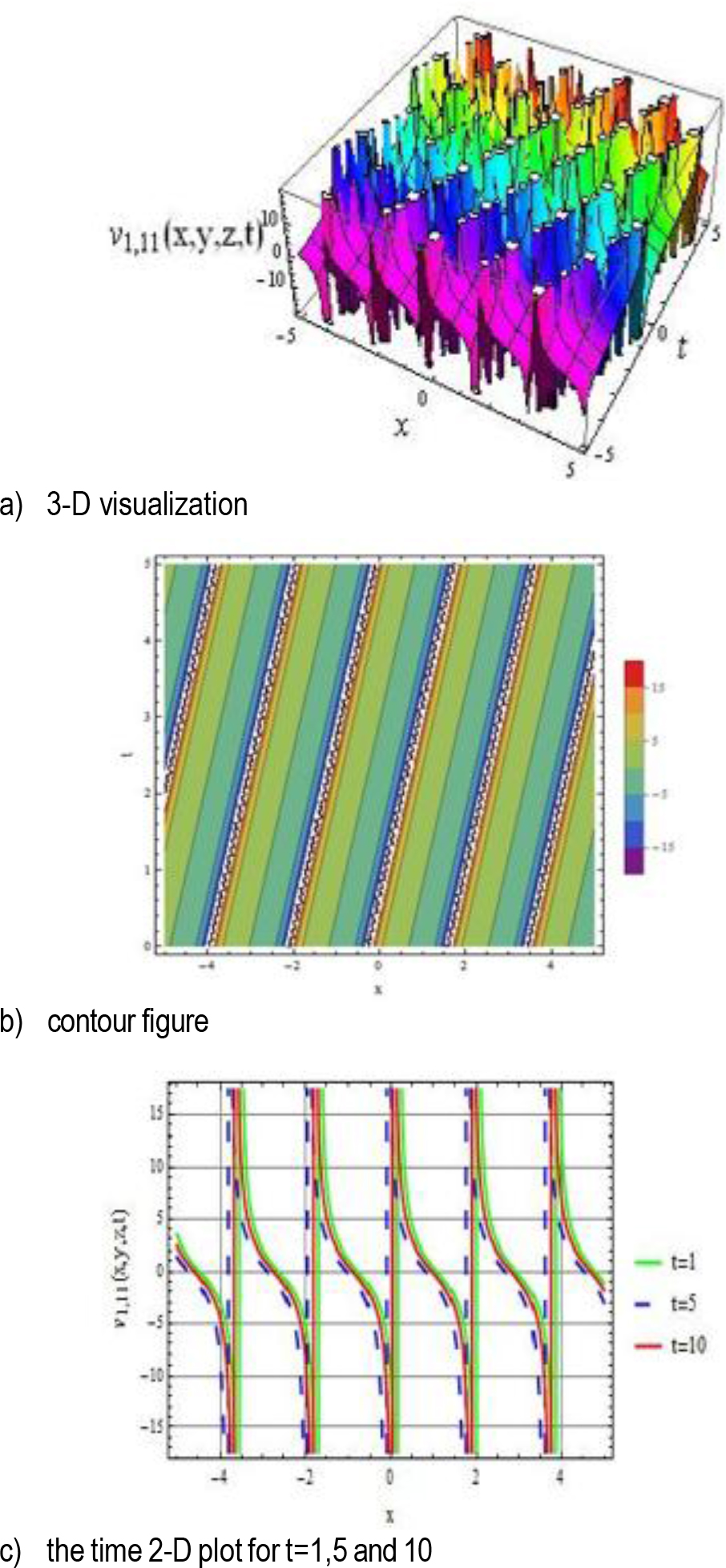
Fig. 5.
The 3-D visualization, contour plot, and 2-D graphical representation of V1,11(x, y, z) are presen-ted for the parameter values k = 0.5, r = 1.5, p = –2, q = –2, and y = z = 1
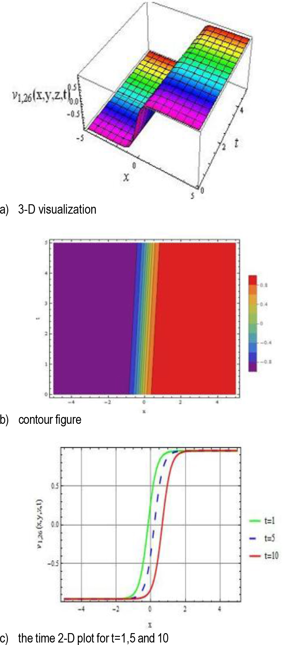
Fig. 6.
The 3-D visualization, contour plot, and 2-D graphical representation of V1,26(x, y, z) are presented for the parameter values r = 2.5, p = 2, q = 𠀓2, and y = z = 1
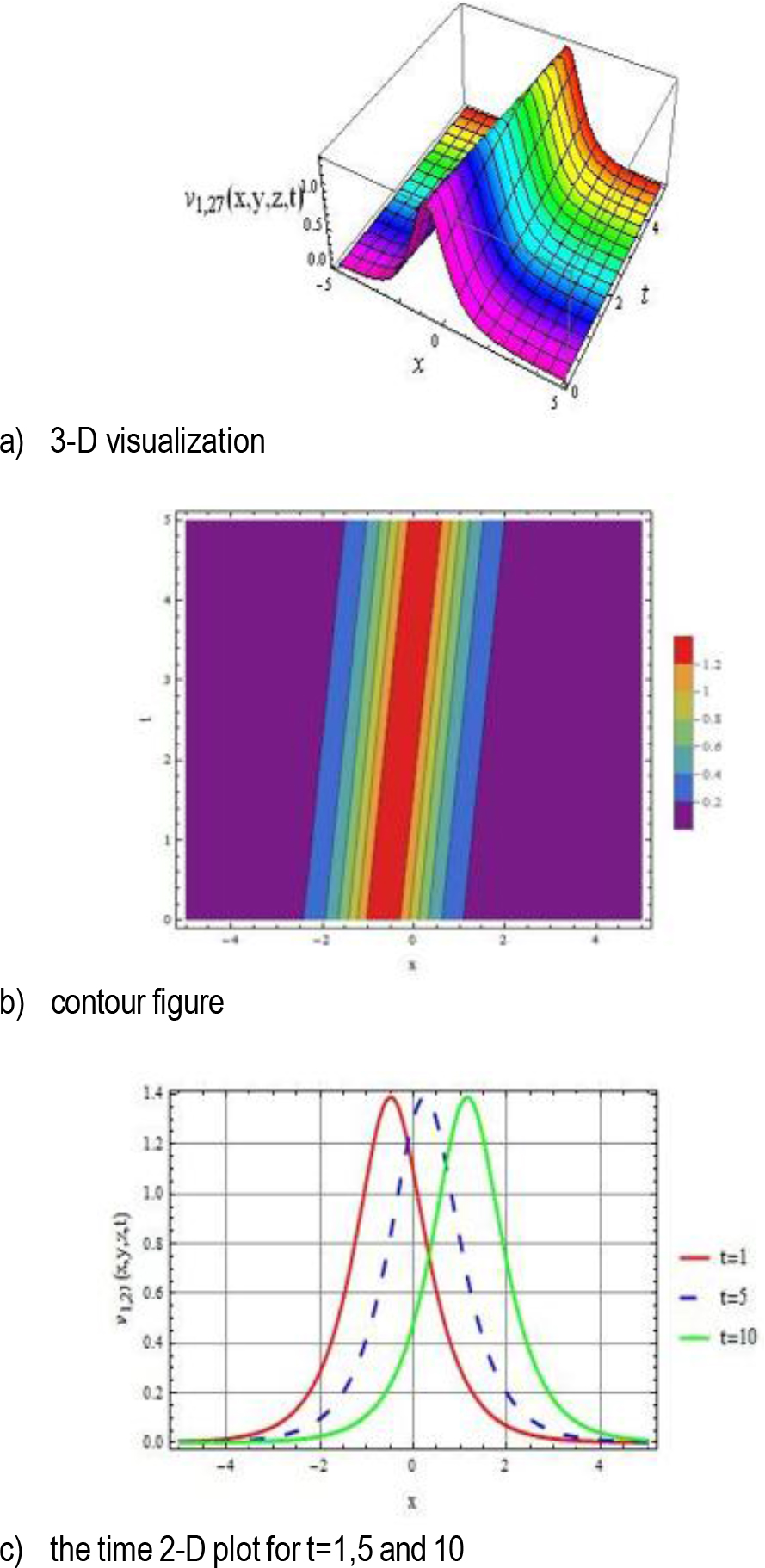
Fig. 7.
The 3-D visualization, contour plot, and 2-D graphical representation of V1,27(x, y, z) are pre-sented for the parameter values r = 3, p = 1.5, q = –2, and y = z = 1
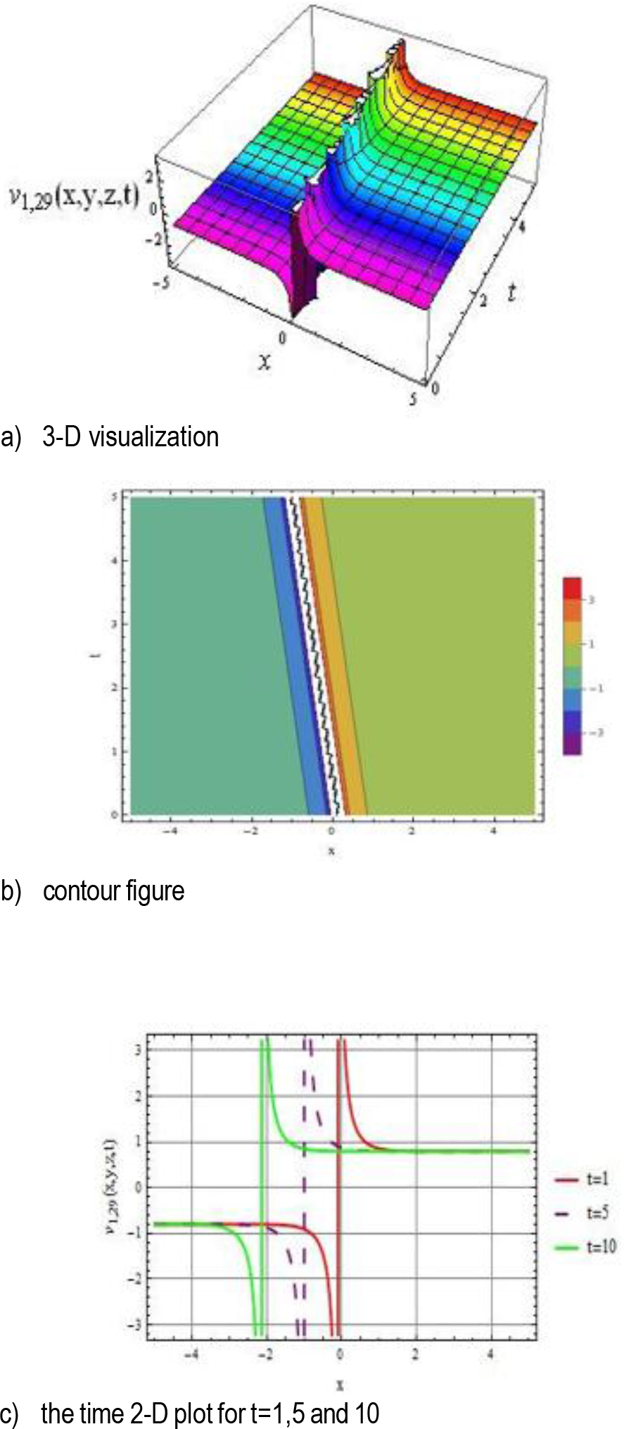
Fig. 8.
The 3-D visualization, contour plot, and 2-D graphical representation of V1,29(x, y, z) are presen-ted for the parameter values r = 1.8, p = 1.5, q = –2, and y = z = 1
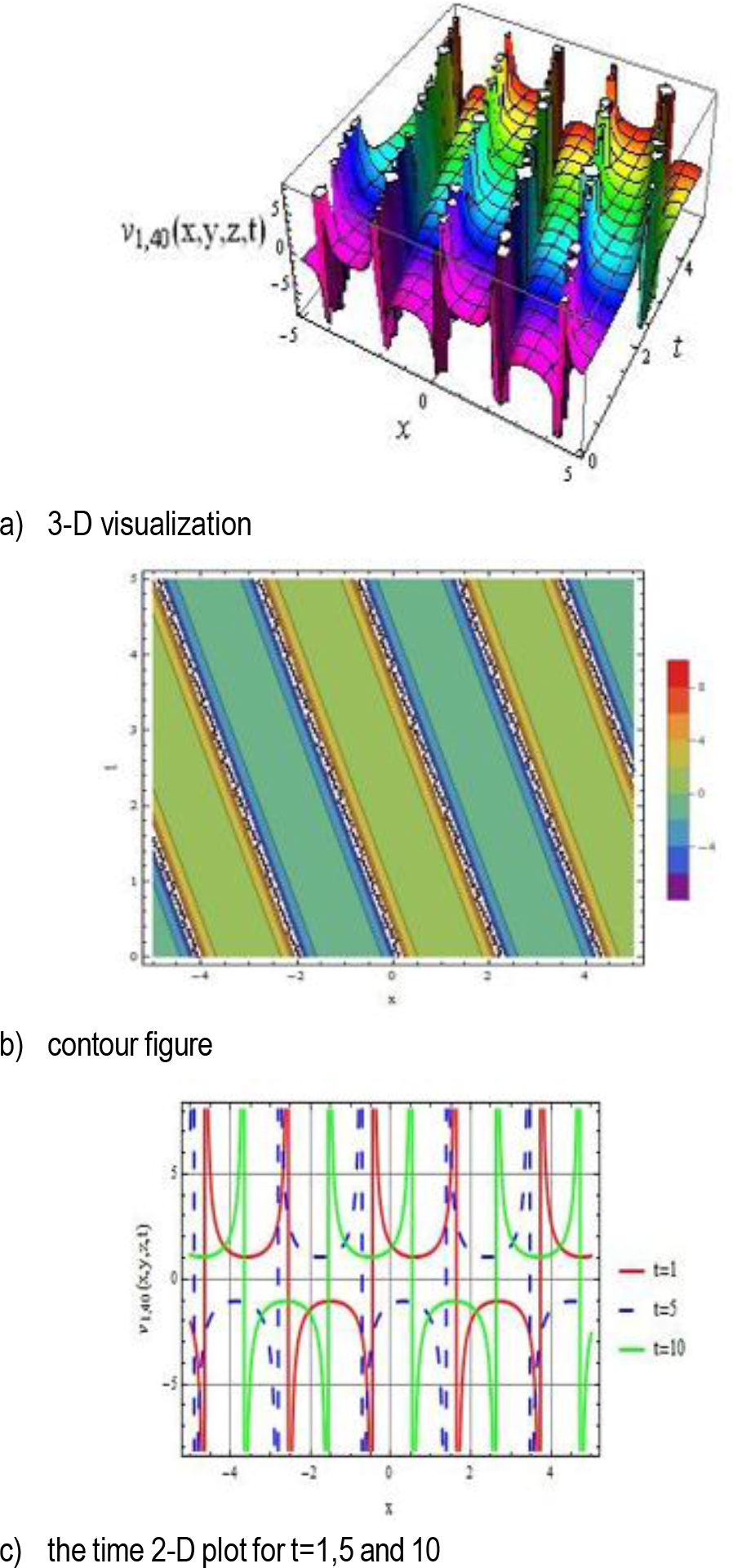
Fig. 9.
The 3-D visualization, contour plot, and 2-D graphical representation of V1,40(x, y, z) are presented for the parameter values r = 1.8, p = 1.5, q = –2, and y = z = 1
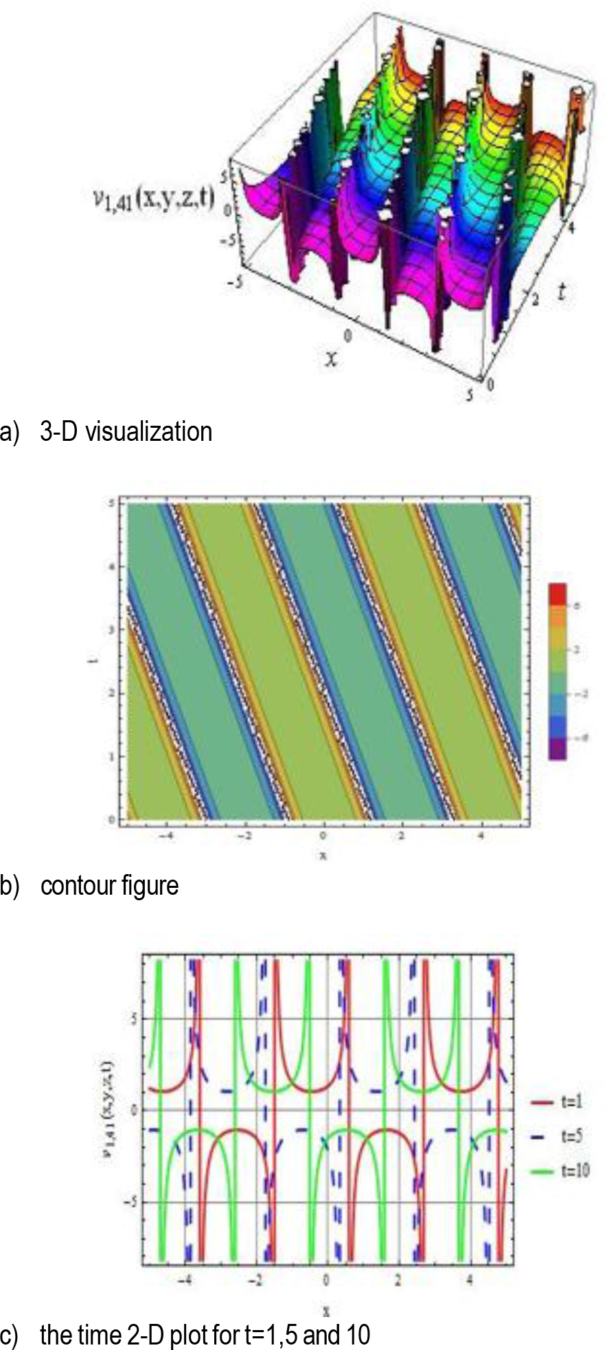
Fig. 10.
The 3-D visualization, contour plot, and 2-D graphical representation of V1,41(x, y, z) are pre-sented for the parameter values r = 1.8, p = 1.5, q = –2, and y = z = 1
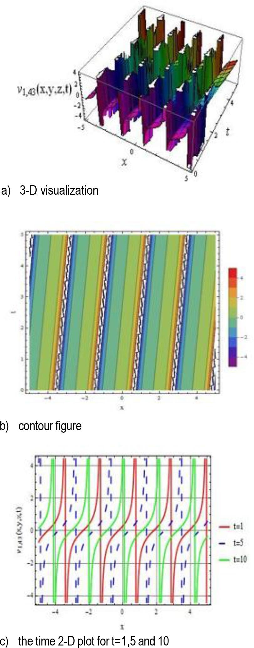
Fig. 11.
The 3-D visualization, contour plot, and 2-D graphical representation of V1,43(x, y, z) are pre-sented for the parameter values r = 1.8, p = 1.5, q = 2, and y = z = 1
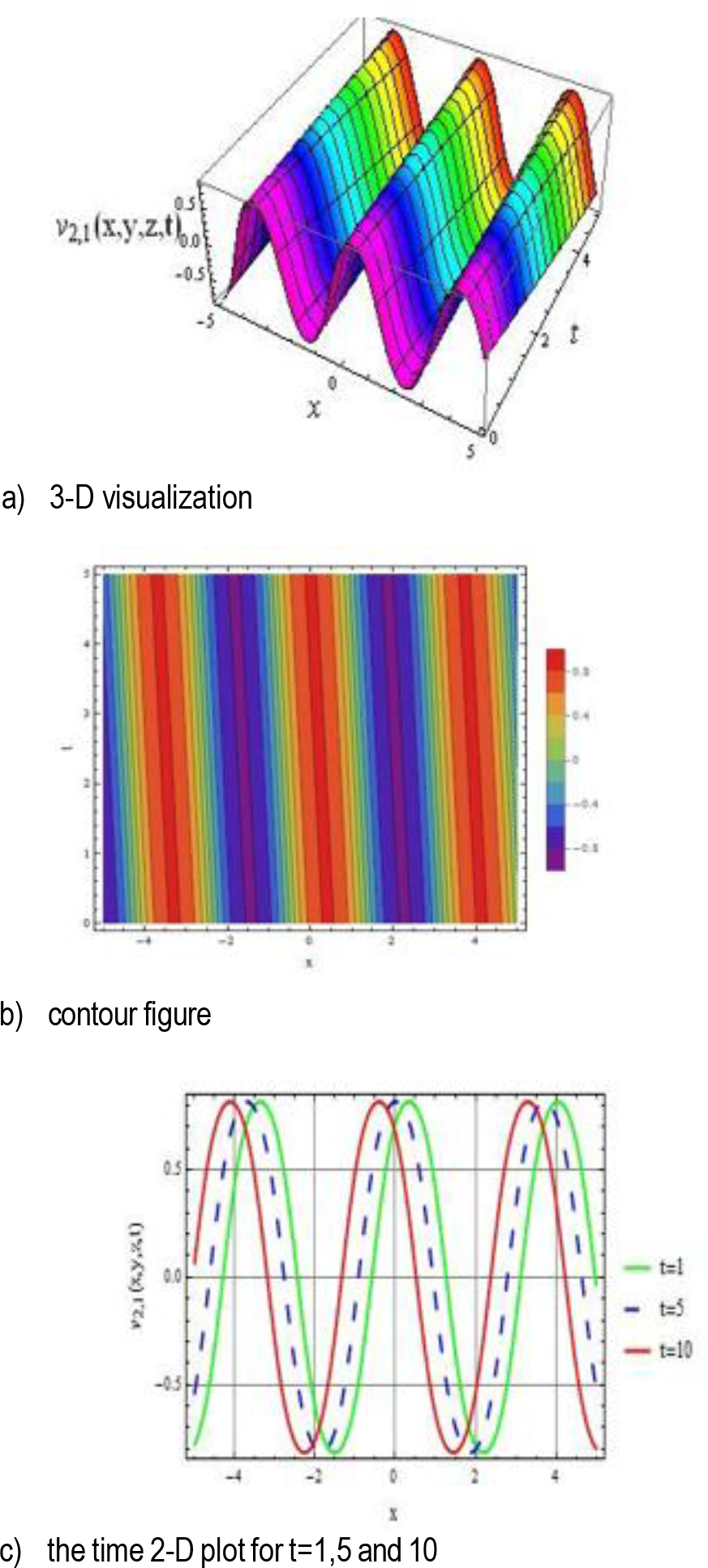
Fig. 12.
The 3-D visualization, contour plot, and 2-D gra-phical representation of V2,1(x, y, z) are presented for the parameter values k = 0.5, r = –1, p = 2, q = 2, y = 1, and z = 1
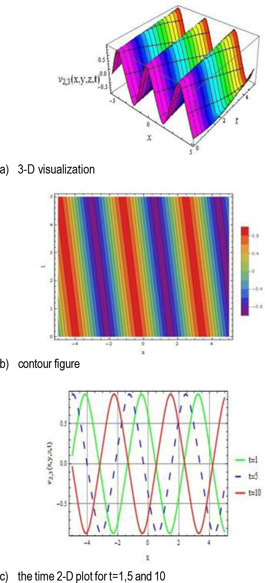
Fig. 13.
The 3-D visualization, contour plot, and 2-D graphical representation of V2,3(x, y, z) are pre-sented for the parameter values k = 0.5, r = –1, p = 2, q = 1.5, y = 1, and z = 1
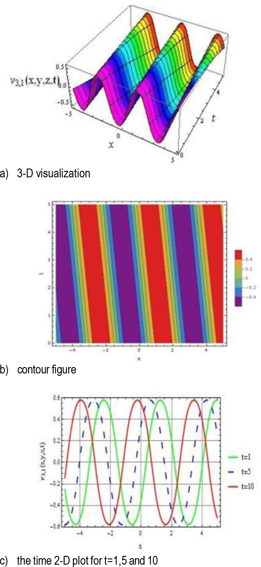
Fig. 14.
The 3-D visualization, contour plot, and 2-D graphical representation of V3,1(x, y, z) are pre-sented for the parameter values k = 0.5, r = 1, p = 2, q = –2, y = 1, and z = 1
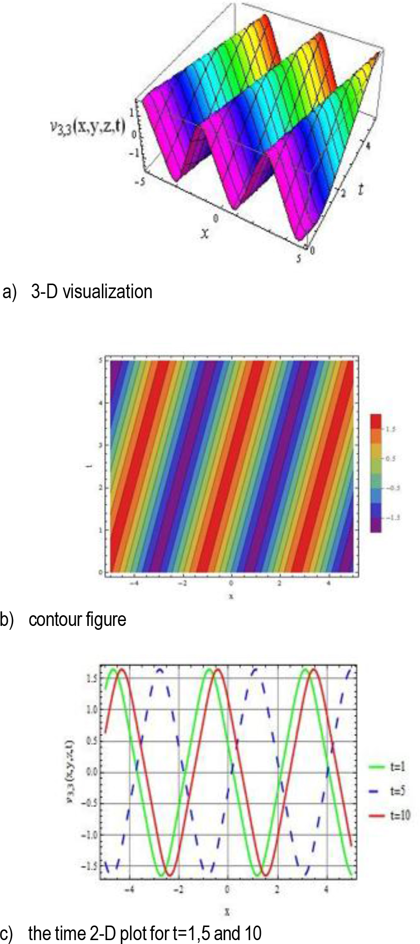
Fig. 15.
The 3-D visualization, contour plot and 2-D graphical representation of V3,3(x, y, z) are presented for the parameter values k = 0.6, r = 0.5, p = 2, q = 2, and y = z = 1